US2575756A - Exhaust machine - Google Patents
Exhaust machine Download PDFInfo
- Publication number
- US2575756A US2575756A US122688A US12268849A US2575756A US 2575756 A US2575756 A US 2575756A US 122688 A US122688 A US 122688A US 12268849 A US12268849 A US 12268849A US 2575756 A US2575756 A US 2575756A
- Authority
- US
- United States
- Prior art keywords
- oven
- lamp
- chamber
- head
- air
- Prior art date
- Legal status (The legal status is an assumption and is not a legal conclusion. Google has not performed a legal analysis and makes no representation as to the accuracy of the status listed.)
- Expired - Lifetime
Links
Images


Classifications
-
- H—ELECTRICITY
- H01—ELECTRIC ELEMENTS
- H01J—ELECTRIC DISCHARGE TUBES OR DISCHARGE LAMPS
- H01J9/00—Apparatus or processes specially adapted for the manufacture, installation, removal, maintenance of electric discharge tubes, discharge lamps, or parts thereof; Recovery of material from discharge tubes or lamps
- H01J9/38—Exhausting, degassing, filling, or cleaning vessels
- H01J9/39—Degassing vessels
Definitions
- Our invention relates to machines for exhausting lamps, discharge tubes and similar electrical devices comprising an enclosing envelope. More particularly, our invention relates to the multiple-station type of machine for exhausting the envelope of such electrical devices automatically and at a high rate of speed.
- Machines for exhausting incandescent and fluorescent lamps .as well as other electric devices having an enclosing envelope provide for the heating of said devices to assist in the removal of contamination on the interior surfaces and occluded in the envelope and other parts thereof.
- the heating function of the exhaust machine also effects treatment of a coating on the envelope. -An instance of this kind is Where the heat has the function of eliminating a binder used to secure the fluorescent powder to the envelope.
- One object of our invention is to provide an exhaust machine having means to heat an electric device of the class described which means is particularly adapted to accurately control the temperature of all portions of the electrical device and capable of rapidly raising and maintaining a relatively elevated temperature therein.
- a machine attaining this object has means remote from the electrical devices for heating air under controlled conditions and other means for blowing a flood of said heated air over the electrical devices. No variation in temperature can occur in the various parts of the devices in this manher of heating and a very rapid rise in the temperature of the device is readily produced.
- Such a machine permits the use of critical manufacturing schedules of greater effectiveness than usual commercial procedures and accordingly allows the manufacture of improved electrical devices.
- This machine is also advantageous in that it eliminates the need for larger and more costly apparatus.
- Another object of our invention is to provide exhausting and heating apparatus well adapted to treat fluorescent lamps comprised of envelopes of extended length and concentrations of mass in the form of electrode assemblies at opposite ends. Such lamps are often eight feet in length and therefore are difficult to heat rapidly to a desired temperature without excessively heating certain portions. Still further difiiculty is encountered in treating fluorescent lamps in that it is only practical to hold said lamps in a vertical position in exhausting apparatus thereby necessitating the use of an oven of considerable vertical extent which normally gives rise to strong in that connection, movable doors are provided to block the opening through which the lamps pass into or out of the oven.
- the oven doors which are requiredat opposite ends of the oven, are preferably in the form of a plurality of blades extending radially from vertical shafts and are partially contained within pockets within the oven in such a manner that the rotation of the shafts causes certain blades to block the openings to the oven while the lamps are carried into or out of said oven in the space between the blades.
- the electrical device is supported by means extending through an opening in the top of the heat chamber of the oven, which chamber has walls made of sheet metal strips suspended from the top adjacent said opening.
- This construction allows the thermal expansion of said walls to be absorbed in means at the bottom of the strips and in loose lock seams between strips and is of still further advantage in that it maintains the relative relation of the top of the oven and the lamp holders.
- This latter condition contributes to the proper association of shields on each lamp holder with the top surface of the oven so that said shields effectively block the passage of air from the opening therein.
- the lack of space between the inner part of the oven and the exhaust machine had made it necessary to use very little insulation on the oven.
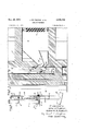
- Fig. 1 is a plan view of a species of exhaust machine comprising our invention, with an overlying portion of one quarter section thereof including the oven removed to show the course of movement of the discharge lamps being treated and the construction of the oven;
- Fig. 2 is a perspective view of one of the heads on the carrier or turret;
- Fig. 3 is a perspective view of the air heating and circulating means associated with the oven;
- Fig. 4 is a vertical section through the upper portion of the half section of the apparatus including thesovenandi tion, corresponding to Fig. 4, of the lower portion of the apparatus and shows in particular the lower air circulation passageof the oven and a portion of the air-heating. means;
- Fig. 1 is a plan view of a species of exhaust machine comprising our invention, with an overlying portion of one quarter section thereof including the oven removed to show the course of movement of the discharge lamps being treated and the construction of the oven;
- Fig. 2 is a perspective view of one of the heads on the carrier or tur
- FIG. 6' is a perspective view with ya portion broken therefrom, of thelower portion of the lamp holding meansof a head of the apparatusand of the lamp imposition therein; and Fig. 7 is anelevationoi the entrance end of the oven, and of a head in the. course of passing between the. partitionsof the door of said oven.
- the apparatus disclosed in thedrawingsjis constructed and arranged so as to. hold a single relatively long (8. foot).
- fluorescent type dischargev lamp in each of a pluralityof work heads .I mounted about the periphery of the carrier or turret 2. and so. as to efiect the. heating. thereof automatically during the movement of said heads. Iv around; the apparatus under the influence ofthe. turret 2.,
- The. lamps .3; (Figs. 2 and 4) are suspended in vertical position directly below the main portion of the heads .1 which overhang the, periphery of the, turret 2 in ver ylmuch the same. manner as, in the apparatusdisclosed in United. States Patent 2,247,513, Marshaus'.
- the lamps. pass r u h a. series of manufaiituring:..silflps. correspending to that performed by the patentlanrp ratus.
- Th man facturin s ps include. the. e tin and as; l i g tr tm nt fec ed; th ou h m por i n of. thehead I directlyassociated with the turret 2 and to which the upper end of the lamp 3. is connected, and other treatments effected by apparatus located directly below said head portion and-along; the course of movement vof the main portion of the lamp ⁇ .
- the first step in the cycle of operations of the; present apparatus occurs when the lamp 3,is in: serted either mechanically or manually into the heads I then located at station A or B.
- the lamp 3 ' is manipulated so that'theexhaust tube '4 at the upper end thereof is carried upward into the opening at'the center of the'ex haust chuck of the head I and so that the long tubular envelope 6 is placed between various pairs of jaws and 8- of a downwardly extending holder of-thehead I.
- the insertion operation also includes resting the lower end of' the envelope '6' inthe cup 9 (Figs. 5 and 6) onthe lowerportion
- the exhaust chuck- 5- is the means. of connecting the 1amp-3 to.:a: conduit I0.
- Successive movements of the head I advance a group-of thirteen'work stations occupied by an oven I2 which i constructed so as to receive the entire lamp 3 and the depending portion of the head -I located below the exhaust chuck 5.
- the oven I2 is equipped with rotatable doors I3 at the;.-entr ance and exit, ends. thereof: to prevent the loss. of;air and to avoid drafts within the oven 5-21 which could disturb the heat. balance, thereof.v
- t e l mp isheated un formly from end to, nd by a flood. of: heated air forced upward therethrou
- Subs quent indexing movementsoi the'work head I carry the lamp 3. compl ely h gh e oven. I2 and then.
- a nut 23 upon the end of the bolt l6 permits the cup 9 to be detached from the piston I! and easily replaced with another of dilierent size if desired.
- the posts I!) of the holder of each head l of the apparatus are attached to a lateral portion of the main body 24 of the exhaust chuck 5 and are joined at their lower ends by a circular band 25 of metal extending completely around the apparatus, which band 25 keeps the lower ends of said posts H3 in proper alignment.
- the jaws l and 8 of the holder therefore are caused to separate sufiiciently to permit the lamp envelope 6 to pass therebetween.
- This operation is effected by manual pressure against the hand lever 26 located adjacent the exhaust chuck 5 so that the vertical shaft 2! on which it is mounted, and the jaws 8 below at various positions along its length, are turned sufficiently to allow the lamp 3 to be pressed against the stationary jaws I.
- Insertion of the lamp 3 is completed by a manually produced upward movement of the lamp 3 which threads the end of the exhaust tube L 4 through the. opening in shield l5 and into the opening in the expansible packing ring 30 of the exhaust chuck 5 and by manipulation of the hand lever 3
- the lamp 3 is advanced to work station C from work station B by the index of the head I and in so doing is introduced to the first operation of the apparatus having to do with the exhaustion and filling thereof.
- This operation is effected by the rotation of the upper half 33 of the rotary valve H,- Which is joined to the turret 2 by the stud 34, to a position where the passage 35, connected by the conduit Ill and the chuck 5 to said lamp 3, is over a passage corresponding to that shown at 36 in the lower stationary half 31 of the rotary valve H.
- the pipe 38 connects passage 36 to the main source (notshown) of vacuum.
- the exhausting operation continues throughout the entire period the lamp 3 remains at station 0 and is only interrupted when the periodic index of the turret 2 moves the head l and the upper half 33 of the rotary valve II to a succeeding position.
- the indexing movement carrying the head I from" station C continues the exhausting and gasfilling operations by again making a suitable connection to the head I through the rotary valve l l and initiates the first step in the introduction of the lamp 3 in the oven l2 by causing said lamp 3 to be carried between two of the partitions or blades 40 of the rotatable door [3 at theentrance passes into position behind the lamp 3 and blocks said entrance.
- the lamp 3 then has a position corresponding to the lamp 3 shown at station D (Fig. 1) on the opposite side of the turret.
- the oven door l3 comprises a plurality of blades 43 of the same height as the entrance opening and the pocket 40 in the oven [3, which blades 43 radiate from a central shaft 4
- the door I3 is turned by the engagement of fixed rollers 43, located between the heads I on arms 44 extending from the body portions 24 of the exhaust chucks 5, with the notches in the periphery of the wheel 45 at the upper end of the shaft 4
- Other notches 43 in the periphery of the wheel 45 provide clearance for the exhaust chucks 5.
- the oven door 13 reduces the loss of heat from the entrance to a minimum and in that connection functions in cooperation with a metal shield 41 covering all of the bottom end of the oven pocket 40 except a clearance slot for shaft 4
- the shield 41 is positioned so as to be wiped by the bottom edges of the several blades 43 of the door l3 engaging the walls of the oven l2 and therefore is in position to prevent the escape of heat downward between said blades 43.
- the shields 48 and 49 are positioned so as to be wiped by the top edges of the blades 43' of the door [3 and close off the upward passages between the particular blades 43 adjacent the oven [2 except for a passageway provided to accommodate the posts l3 and shafts 21 of the heads I.
- the arcuate shield 115 which rests on the head of a stud 43 extending from the bottom of the body 24 of each exhaust chuck 5, closes the space between shields 48 and 49.
- is mounted around that portion thereof adjacent said stations A and B in a position to intercept said heat.
- the oven door I 3 also provides a means of entering the interior of the oven l2 in that the arms 42 engaging the central shaft 4
- the succeeding index of the head I carries the lamp 3 further into the oven I2 and away from between the blades 43 of the oven door 13, and positions said lamp 3 at the first of a series of stations within the heat chamber of the oven I 2.
- Ten succeeding stations are located within the oven chamber, which is defined by two relatively closely spaced heavily insulated vertical walls of said oven [2, and in each of said stations the lamp 3 is correspondingly subjected to the heat of a flood of air circulated upward therebetween.
- All heat contained within the oven chamber is supplied by the influx of heated air into the lower portion of said chamber from a large plenum chamber 56 located to one side thereof and is heat 7 generated outside of the walls of said oven l2 in airrecirculated after being withdrawn-through a corresponding plenum chamber 51 at the top thereof.
- the air passes between the plenum chambers 56 and 51 and the oven chamber desired temperature in at parts of the oven [2 can be maintained by the flow of air produced by the blower 519 without difliculty and inan efficient manner.
- Heating means of the type disclosed provides accurate control of the temperature in the lowest and most extended portions of the oven l2 since said air is circulated between the extremities of the oven j 2 and avoids as much as possible inward leakage of cool air, vertical Variations efiected by convection currents and.
- the rapid circulation of heated air also promotes very rapid transference of heat to the lamp. 3 thereby lessening the period of treatment required and by the accurate maintainanceof temperature permits more desirable but more critical heat treatments to be used.
- the circulating means associated with the oven l2 provides for drawing air from the top of the full lineal extent of the vertical heat chamber forming the lamp-holding chamber of the oven [2 and withdraws the air through the laterally directed passageway 51 which extends as near as practical to the entrance and exit ends of said heat chamber.
- the exhausted air traveling'out through passage 57" and plenum is gradually drawn into the circularfiowpattern of the connected pipe 58 Whichconducts itxto the inlet opening of the centrifugal typeblower 59.
- the heated air which conditions the heat chamber and; consequently the lamp 3, enters the bottom of said chamber from the passage; .59 which extends the full lineal extent thereof :in the manner of passage 5?
- Baiiies SL 62, and 63 (Figs. 1 and 5) are provided. at thecenter of the discharge end of the passage 56? directly opposite the outlet of the heater 68 to impede the flow of air suliiciently to promote the desired flow from the opposite extremes oisaid discharge end and to effect a controlled direction of flow of air into the heat chamber ofthe oven i2.
- the baffle 62 blocks the direct flow ofair from the lower end of the lamp 3, whereas the baffles.
- the lamps 3 contained within the oven l2 are always exposed to the circulaticn'of heated air in that the blower as, which is driven by the electric motor 65, is continuously operated.
- the electric motor 65 drives the fan (not shown); of the blower fiil through the belt 66 and the pulleys 61 and 68 on the motor and fan shaits 69 and respectively and at such a rate as to move the air around the lamps 3 in the major partof the heat chamber at a velocity of some 300 feet per minute.
- This rapid rateof circulation enables lamps 8 feet in length to be quickly raisedto the temperature of treatment which in the present instance is in the order of 550 C. Accurate maintenance of this treatment temperature is also accomplished by the circulation of the heated'medium as the electric resistance ele-.
- ments H which necessarily operate at a higher temperature than the surrounding air, are remote from the lamp 3 and the only heat transferred thereto is that of the circulating air which is subject to accurate control.
- the temperature of the heat treatment is automatically maintained by electric means (not shown) con;- trolledby thermocouples (not shown) at various positions within the oven 42 and capable ,ofbeing preset over a wide range to the temperature desired. 7
- Expansion and contraction of the highly heated inside portions of the oven l2 is'provided for by having the longer sections of the walls of the heat chamber formed from overlapping strips 72 and 13Yof vertically arranged sheet metal fastened at the top to cool and therefore relatively fixed support members of the oven i2 and by keeping said strips taut by a downward pull on the lower ends thereof.
- the strips 12 forming the wall of the heat chamber-adjacent the center-of the machine hang from a rod supported by structural members 15 and 16 extending through a relatively cool portionof the oven 12 to the base of the machine, whereaathe strips i3 forming the oppositeside of the heat chamber hang from the edge of a plurality of P brackets 11 mountedon a crossstructuralmem ber 18 in turnsupported by-beams l9 and 80.
- Loose lock seams-8i (Fig. 1) are provided be tween adjacent strips 12 and 73.
- each of the strips l2 and 13 is pulled taut by a rod 82 extending downward through the bottom of the oven l2 where a spring 83 located between a nut onthe end thereof and the bot tom of the oven 12 exerts a constant pull there.- on.
- the above type of oven construction fixes the top portion'of the oven 12 withinrelatiyely close limits during all conditions of heat and thereby assures a. substantially fixed relation between the parts of theheads I and the adjacent portion of said oven l2.
- the lamp' holder of the head i and the exhaust tube 4 ofthe lamp 3 are accommodatedin an opening in the top of the oven 12 along their course of movement, which opening is blocked ofiby the shield [5 carried by each head I.
- the height of the oven 12 is such that the shields l5 ride up onto the top surface thereof when the head I passes into operative relation to said oven 12 and remain in contact with said surface during the entire interval said relation cons tinues. Since eachshield isis'separate from the others, independent vertical movement of each can occurand positive engagement between each shield l5 and the top of the oven i2 is assured under any normal variation.
- the head I advances said lamp 3 into proper operating arrangement with other means not herein disclosed but corresponding to that shown in the Marshaus Patent 2,247,513, which provides for certain other treatments to said lamp 3 and finally the tipping off of the exhaust tube 4.
- the exhausting and filling operations occurring during the above course of movement are also completed in a manner corresponding to that disclosed in the said Marshaus patent under 'the control of the rotary valve H and, correspondingly, a controlled quantity of mercury is discharged into the lamp 3 through the exhaust chuck 5 by operation of the dispenser or doser 85 which is a unit of the head I directly above said exhaust chuck 5.
- the heads I are each separately cooled by the flow of water passing through the short passage 86 in the body 24 of the exhaust chuck 5.
- the cooling water flows from a source provided by the stationary pipe Bl located on the axis of rotation of the turret 2 and passes through lateral openings therein to an opening behind the rotatable ring 88 of the stufiing box 89 and thence through openings in said ring 88 and the pipe ill! to one end of the passage 86 in the head I.
- the water is drained from the opposite end of the passage 86 through pipe 9! to the stationary open trough 92 which extends completely around the apparatus under the turret 2 and which is provided with a suitable drain pipe.
- Support for the trough 92 is provided in brackets 93 located at spaced intervals about the apparatus and engaging the upstanding posts 94 of the frame of the apparatus.
- the posts 94 also add further support and stiffness to the turret 2 by furnishing, through the medium of the roller 95 in the yoke 96 on the upper end thereof, a rest upon which the lower edge of the rib 9! in the turret 2 seats throughout the course of rotation thereof.
- An exhaust machine for electric lamps or similar devices comprising a head for holding and making a gastight connection to a lamp, a carrier for supporting the head and advancing it to each of a plurality of stations, means connected to the head for effecting evacuation of the lamp at certain of said stations, an oven mounted adjacent the path of movement of said head and including a chamber for receiving the lamp, and air circulating means connecting opposite extremities of the oven in a closed circuit comprising a blower and air heating means for directing a flow of heated air through the said chamber.
- An exhaust machine for elongated electric lamps or similar devices comprising a head for holding a lamp in a vertical position and making a gastight connection thereto, a carrier for supporting the head and advancing it to each of a plurality of stations, means connected to the headfor effecting evacuation of the lamp at certain of said stations, an oven mounted adjacent the path of movement of said head and including an elongated chamber for receiving the lamp, and air circulating means connecting the upper and lower extremities of the oven in a closed circuit comprising a blower and air heating means for directing a flow of heated air upward through the said chamber.
- An exhaust machine for electric lamps or similar devices comprising a head for holding and making a gastight connection to a lamp, a carrier for supporting the head and advancing it to each of a plurality of stations, means connected to the head for effecting evacuation of the lamp at certain of said stations, an oven mounted adjacent the path of movement of said head including a chamber open at the top and terminating in openings in the ends thereof for receiving the lamp, movable doors at the opposite ends of the oven closing off the openings therein, means for actuating the doors to permit the lamp to pass to and from the oven, a shield mounted on the head and engaging the upper surface of the oven for closing the top opening therein, and air circulating means connecting the upper and lower extremities of the oven in a closed circuit comprising a blower and air heating means for directing a flow of heated air upward through the chamber thereof.
- An exhaust machine for electric lamps or similar devices comprising a head for holding and making a gastight connection to a lamp, a carrier for supporting the head and advancing it to each of a plurality of stations, means connected to the head for'effecting evacuation of the lamp at certain of said stations, an oven mounted ad acent the path of movement of said head including a chamber open at the top and terminating in openings in the ends thereof for receiving the lamp, doors rotatable about a vertical axis at the opposite ends of the oven having blades radiating from said axis and arranged to wipe opposite walls of the openings therein, means engaged by the head during movement thereof to and from operative relation to the oven for rotating the doors to cause the blades: thereof to pass successively to opposite sides of the lamp held by the head and to positions to close said openings, and air circulating means connecting the upper and lower extremities of the oven in a closed circuit comprising a blower and air heating means for directing a flow of heated air upward through the chamber thereof.
- An exhaust machine for electric lamps or similar devices comprising a head for holding and making a gastight connection to a lamp, a carrier for supporting the head and advancing it to each of a plurality of stations, means connected to the head for effecting evacuation of the lamp at certain of said stations, an oven mounted adjacent the path of movement of said head including semi-circular pockets in the ends thereof and a chamber open at the top and terminating in said pockets for receiving the lamp, rotatable doors mounted on a vertical axis within the pockets of the oven having blades radiating from said axis and arranged to wipe the walls of said pockets, means engaged by the head during movement thereof to and from operative relation to the oven for rotating the doors to cause the blades thereof to pass successively to opposite sides of the lamp held by said head and to positions in the pockets to close the openings therein, and air circulating means connecting the 'a'svtfrse i1 upper and lower extremities of the oven a closed "circuit comprising'a blower and air heating means for directing a closed
- heating means comprising an oven' incliiding a chamber "for receiving the lamp terminatin i epenings'mthe ends thereof and including lateral passages at the top and bottom o'ffthe chamber extending substantially the full iengartnerem for decanting heated at therethrough, a, deflector located within the oven at the unthie fjonel ateral'passa ge and the chamher for redirecting an d restricting the inflow of air from' s'aidjpassage to said chamber, movable doors 'oat oppositeends of the oven for closing off the Qpeni'ngs therein, and air -circ u laftiijig' ns connecting the passages 'in the eve in h oug hg h mb L r j 8.
- heating means comprising an oven including a chamber for receiving the lamp terminating in openings in the ends thereof and including lateral. passages at the top and bottom oi thecham-berextending substantially the full length thereof for circulating heatedair therethrough, deflectors-located within the oven opposite theendof one lateral passage for blockin'gthedirect'fibw of air therefrom to the chain'- berfand redirecting said flow along the walls thereof, movabledoors at opposite ends of the ovenfor closing off the openings therein, and air circulating means connecting the passages in the even in agclosed circuit comprising blower and airfheating means for directing a flow of heated ai throughfthe chamber.
- heating means comprising an oven'including semi circular pockets in the ends thereof, a chamber terminating in said pockets gorgrebe vm the lamp and lateral passages at the topand bottom extremitiesof the chamber extending substantiallythe full length thereof,
- rotatable doors located within pockets of theoven having blades radiating from theaxis of rotation and arranged to wipethe walls of saidpockets, means to rotate the doors to cause the blades thereof to pass successively tobpposite sides of the lamps entering and leaving the chamber of the oven and to positionswithin the pockets to close off the chamber, deflectors located within the oven opposite the end of the lower lateral passage for blocking the direct flow of air therefrom to the chamber and proportioning said now along the walls thereof, and air circulating means connected to the lateral passages in the oven and forming a closed circuit therebetween comprising a blower and air heating means effecting a rapid circulation of heated air from the bottom to the top of the chamber in said oven.
- heating means comprising an oven including a chamber for receiving the lamp terminating in openings in the ends thereof and formed from relatively narrow overlapping parallel strips of material, movable doors at opposite ends of the oven for closing off the openings thereimand air circulating means connecting the upper and lower extremities of the oven in a closed circuit comprising a blower and air heating means for directing a flow of heated air through the chamber thereof.
- heating means comprising an oven including a chamber for receiving the lamp terminating in openings in the ends thereof and formed from relatively narrow overlapping parallel strips of material, and including fixed support means for one end of the Strips and means for exerting a constant pull onto the other end of said strips to absorb longitudinal expansion therein, movable doors at opposite ends of the oven for'closing the openings therein, and air circulating means connecting the upper and lower ed circuit comprising' ablower and air heat: I in means for directing a now of heated air extremities of the oven in a closed circuit comprising a blower and air heating means for directing a flow of heated-air through the chamber thereof. 7
- heating means comprising an oven including a chamber terminating in openings in the ends thereof for allowing the lamp oven in a closed circuit comprising a blower and air heating means for directing a flow of heated air through the chamber thereof.
- heating means comprising an oven including a chamber terminating in openings in the ends thereof for allowing the lamp to enter and leave said chamber, and having an opening extending between said first-mentioned openings in the ends for permitting constant engagement with the lamp in said chamber, said chamber being formed from relatively narrow overlapping parallel strips of material, fixed support means for the ends of the strips adjacent the last-mentioned opening in the chambervof the oven extending externally of said oven, means for exerting a constant pull onto the other end of said strips to absorb longitudinal expansion therein, movable doors at opposite ends of the oven for closing the openings therein, and air circulating means connecting'the upper and lower 13 extremities of the oven in a closed circuit comprising a blower and air heating means for directing a flow of heated air through the chamber thereof.
- An exhaust machine for electric lamps or similar devices comprising an oven including an insulated chamber, a carrier including means to support lamps and carry them along a path 01' travel through said oven, means including ex-- haust heads on said carrier for connecting the lamps to a source of vacuum, a heating unit, a blower, and means connecting said heating unit and blower with said oven chamber in a closed circuit to recirculate heated air therethrough,
- An exhaust machine for electric lamps or similar devices comprising an oven including an insulated chamber having walls made of relatively narrow vertical strips of sheet metal attached to each other by loose lock seams to permit expansion thereof without warping, a carrier including means to support lamps and carry them along a path of travel through said oven, means including exhaust heads on said carrier for connecting the lamps to a source of vacuum. a heating unit, a blower, and means connecting said heating unit and blower with said oven chamber in a closed circuit to recirculate heated air therethrough.
- An exhaust machine for electric lamps or 14 similar devices comprising an oven including an insulated chamber having walls made of relatively narrow vertical strips of sheet metal attached to each other by loose lock seams to permit expansion thereof without warping and also including fixed support means for theupper ends of said strips and spring means attached to the lower ends of said strips to keep them taut.
- a carrier including means to support lamps and carry them along a path or travel through said oven, means including exhaust heads on said carrier for connecting the lamps to a source of vacuum, a heating unit, a blower. and means connecting said heating unit and blower with said oven chamber in a closed circuit to recirculate air therethrough.
Description
Nov. 20, 1951 J. w. FULTON ETAL EXHAUST MACHINE 4 Sheets-Sheet 1 Filed Oct. 21. 1949 Invervlrovs:
Johh W. Fulfton, Robevd: A. KuebLeT",
Tl'weiv- A tft'orneg.
Q 1951 J. w. FULTON ETAL 2,575,755
EXHAUST MACHINE Filed Oct. 21, 1949 4 Sheets-Sheet 2 lnven t'ovs John W. Fukt'oh,
Their- A lr irovneg.
Roberi A. KuebLer,
Nov. 20, 1951 J. w. FULTON ET AL EXHAUST MACHINE 4 Sheets-Sheet 3 Filed Oct. 21. 1949 0) Invewtors:
John W FULt'OTW, Rober-=lr A .l 'uebLeT b5 W a X Their" A=ttrorne5 7 N 1951 J. w. FULTON ETAL 2,575,756
EXHAUST MACHINE Filed Oct. 21, 1949 4 Sheets-Sheet 4 L 54 O O 163 2M 7 v Q lnven t'ors: John W. Fukfon Rober lr AKuebLer, 5 W'%J%MM Their Adrdrorneg.
Patented Nov. 20,1951
UNITED STATES PATENT OFFICE EXHAUST MACHINE John W. Fulton, Chardon, and Robert A. Kuebler, Cleveland Heights, Ohio, assignors to General Electric Company, a corporation of New York Application October 21, 1949, Serial No. 122,688
16 Claims. 1 a
Our invention relates to machines for exhausting lamps, discharge tubes and similar electrical devices comprising an enclosing envelope. More particularly, our invention relates to the multiple-station type of machine for exhausting the envelope of such electrical devices automatically and at a high rate of speed. i
Machines for exhausting incandescent and fluorescent lamps .as well as other electric devices having an enclosing envelope provide for the heating of said devices to assist in the removal of contamination on the interior surfaces and occluded in the envelope and other parts thereof. In certain instances, the heating function of the exhaust machine also effects treatment of a coating on the envelope. -An instance of this kind is Where the heat has the function of eliminating a binder used to secure the fluorescent powder to the envelope.
One object of our invention is to provide an exhaust machine having means to heat an electric device of the class described which means is particularly adapted to accurately control the temperature of all portions of the electrical device and capable of rapidly raising and maintaining a relatively elevated temperature therein. A machine attaining this object has means remote from the electrical devices for heating air under controlled conditions and other means for blowing a flood of said heated air over the electrical devices. No variation in temperature can occur in the various parts of the devices in this manher of heating and a very rapid rise in the temperature of the device is readily produced. Such a machine permits the use of critical manufacturing schedules of greater effectiveness than usual commercial procedures and accordingly allows the manufacture of improved electrical devices. This machine is also advantageous in that it eliminates the need for larger and more costly apparatus.
Another object of our invention is to provide exhausting and heating apparatus well adapted to treat fluorescent lamps comprised of envelopes of extended length and concentrations of mass in the form of electrode assemblies at opposite ends. Such lamps are often eight feet in length and therefore are difficult to heat rapidly to a desired temperature without excessively heating certain portions. Still further difiiculty is encountered in treating fluorescent lamps in that it is only practical to hold said lamps in a vertical position in exhausting apparatus thereby necessitating the use of an oven of considerable vertical extent which normally gives rise to strong in that connection, movable doors are provided to block the opening through which the lamps pass into or out of the oven. According toa feature of the invention, the oven doors, which are requiredat opposite ends of the oven, are preferably in the form of a plurality of blades extending radially from vertical shafts and are partially contained within pockets within the oven in such a manner that the rotation of the shafts causes certain blades to block the openings to the oven while the lamps are carried into or out of said oven in the space between the blades.
According to a still further feature of the invention the electrical device is supported by means extending through an opening in the top of the heat chamber of the oven, which chamber has walls made of sheet metal strips suspended from the top adjacent said opening. This construction allows the thermal expansion of said walls to be absorbed in means at the bottom of the strips and in loose lock seams between strips and is of still further advantage in that it maintains the relative relation of the top of the oven and the lamp holders. This latter condition contributes to the proper association of shields on each lamp holder with the top surface of the oven so that said shields effectively block the passage of air from the opening therein. In accordance with previous practice, the lack of space between the inner part of the oven and the exhaust machine had made it necessary to use very little insulation on the oven. By removing the heating elements from the oven chamber, in accordance with the present invention, it became feasible to apply a comparatively thick wall of insulation to all parts of the oven. This has resulted in a very substantial reduction in the amount of electrical power required, and also provides considerably more comfortable working conditions for the operators.
Still further features and advantages of our invention will appear from the following de-.
of the holderof the head I.
3 tailed description of a species thereof and from the drawing.
In the drawing, Fig. 1 is a plan view of a species of exhaust machine comprising our invention, with an overlying portion of one quarter section thereof including the oven removed to show the course of movement of the discharge lamps being treated and the construction of the oven; Fig. 2 is a perspective view of one of the heads on the carrier or turret; Fig. 3 is a perspective view of the air heating and circulating means associated with the oven; Fig. 4 is a vertical section through the upper portion of the half section of the apparatus including thesovenandi tion, corresponding to Fig. 4, of the lower portion of the apparatus and shows in particular the lower air circulation passageof the oven and a portion of the air-heating. means; Fig. 6' is a perspective view with ya portion broken therefrom, of thelower portion of the lamp holding meansof a head of the apparatusand of the lamp imposition therein; and Fig. 7 is anelevationoi the entrance end of the oven, and of a head in the. course of passing between the. partitionsof the door of said oven.
The apparatus disclosed in thedrawingsjis constructed and arranged so as to. hold a single relatively long (8. foot). fluorescent type dischargev lamp, in each of a pluralityof work heads .I mounted about the periphery of the carrier or turret 2. and so. as to efiect the. heating. thereof automatically during the movement of said heads. Iv around; the apparatus under the influence ofthe. turret 2., The. lamps .3; (Figs. 2 and 4) are suspended in vertical position directly below the main portion of the heads .1 which overhang the, periphery of the, turret 2 in ver ylmuch the same. manner as, in the apparatusdisclosed in United. States Patent 2,247,513, Marshaus'. dated July 1, 1941, and which patent is assigned to the assignee of; the present invention, In thecou-rse of the operation of the apparatus, the lamps. pass r u h a. series of manufaiituring:..silflps. correspending to that performed by the patentlanrp ratus. Th man facturin s ps include. the. e tin and as; l i g tr tm nt fec ed; th ou h m por i n of. thehead I directlyassociated with the turret 2 and to which the upper end of the lamp 3. is connected, and other treatments effected by apparatus located directly below said head portion and-along; the course of movement vof the main portion of the lamp}.
The first step in the cycle of operations of the; present apparatus occurs when the lamp 3,is in: serted either mechanically or manually into the heads I then located at station A or B. At such, times, the lamp 3 'is manipulated so that'theexhaust tube '4 at the upper end thereof is carried upward into the opening at'the center of the'ex haust chuck of the head I and so that the long tubular envelope 6 is placed between various pairs of jaws and 8- of a downwardly extending holder of-thehead I. The insertion operation also includes resting the lower end of' the envelope '6' inthe cup 9 (Figs. 5 and 6) onthe lowerportion The exhaust chuck- 5-is the means. of connecting the 1amp-3 to.:a: conduit I0. leading tov a rotary valve I.-:I. located about the axis of rota-tion of the turret 2 ,-which. valve'l I is. adapted to effect the exhausting: and filling. operations. of the'apparatus in accordance with the rotation of the turret 2 and the location of the head I thereabout. The rotary valve II. and the other directly associated means having to do with the exhausting and filling of the lamp 3 are constructed in accordance with the Marshaus patent hereinbefore referred to, and in general effect changes in these operations in the manner of the patented apparatus; The lamp 3 is'advanced from station A to station B and further along the course of movement to each of the 32 work stations by successive indexing movementsor the turret 2 under influence of driving means (not shown).
Successive movements of the head I advance a group-of thirteen'work stations occupied by an oven I2 which i constructed so as to receive the entire lamp 3 and the depending portion of the head -I located below the exhaust chuck 5. The oven I2 is equipped with rotatable doors I3 at the;.-entr ance and exit, ends. thereof: to prevent the loss. of;air and to avoid drafts within the oven 5-21 which could disturb the heat. balance, thereof.v While enclosed Within the oven I2, t e l mp isheated un formly from end to, nd by a flood. of: heated air forced upward therethrou Subs quent indexing movementsoi the'work head I carry the lamp 3. compl ely h gh e oven. I2 and then. throu h anoth r eroup of work s ations: where. thev lamp 3 is. treated by m a dir yassociated with the work, head I and other m ans (not hown). n r levant o this invention. Finally the lamp 3 arrives; at station E where it is: Sealed oil and: then passes. to station F where; it is, removed. from the. apparatus. The opera-- tigns occurring at this latter group 0t work stations correspond to those occurring in the ma.- chine disclosed in the Marshaus patent hereinbefore refer-red to, and, are performed by means, not shown; in'complete detail in the present application. Full details of the operation of the disclosedapparatus, with particular reference to the portions thereof relating-to the; present. invention; appear, in the followingdetailed description.-
Theinsertion of the l mp 3. in o the appa tus. the step; intheoperation thereon; consists, inres-ting'the completely sealed end ofsaid lampg-e in; the. cup ;9 (Figs. 5; and 6) located onthe.
, lower portion of a holder extending downward,
fromv the: head I, the operation being. performed in. such. a; manner that. the leadingrin wires I; l' Hi5 projecting from that end. of the; lamp it fall into, opposednotches 9! in the rim; thereof. The lamp 3x-is. thenpusheddownward. against the yieldin resistance of the cup. 9yuntil1theiexhaust tubed; (Fig... 4-). at the upperxend. thereof :is; below the level of the shield I;.'i,.whereupon.it;is moved back under saidcshieldr L5. to. alignment with thee eX-' haust chuck .5. andmovedupzinto. proper engagement therewith. The upward pressurexproduced: by. the cup .9. is-..sufficient to support thev lamp. 3 andnisweiiected through the attachment of the boltIfitiFig. 6) extendingfrom cup; 9. to.a.piston I I. within the. tubular" lower portion I 8. of the post I 9. of the holder ofthe head I... The pistonkl l, in turrnais supported byarod'ze extending upward through the full; length of the postiisrand the parts'of the head Ito a nut (Fig; 2') bearingupon the prin 2|. surrounding the upper end thereof and: seating on saidhead. I; Slots 22in. opposite sides. of the lower tubular portion. I8: of the post I39. allow free vertical. motion of the bolt: I 6 iso: thatzdownward pressure upon the cup. 9: which compressesithe spring .21: willlower. said cup. 9.
A nut 23 upon the end of the bolt l6 permits the cup 9 to be detached from the piston I! and easily replaced with another of dilierent size if desired. The posts I!) of the holder of each head l of the apparatus are attached to a lateral portion of the main body 24 of the exhaust chuck 5 and are joined at their lower ends by a circular band 25 of metal extending completely around the apparatus, which band 25 keeps the lower ends of said posts H3 in proper alignment.
At the time the upper end of the lamp 3 is moved under the shield l5 and into alignment with the exhaust chuck 5, the jaws l and 8 of the holder therefore are caused to separate sufiiciently to permit the lamp envelope 6 to pass therebetween. This operation is effected by manual pressure against the hand lever 26 located adjacent the exhaust chuck 5 so that the vertical shaft 2! on which it is mounted, and the jaws 8 below at various positions along its length, are turned sufficiently to allow the lamp 3 to be pressed against the stationary jaws I. The release of pressure against the hand lever 26 permits the contraction force of the spring 23 extending between posts in said lever 26 and the body 24 of the exhaust chuck 5 to turn shaft 21 and carry the jaws 8 against the envelope 6 with sufiicient pressure to clamp it against the stationary jaws l of the holder. Inasmuch as jaws l are fastened directly to post IS, the lamp 3 becomes properly aligned with the head I when pressed thereagainst. The jaws 8 maintain their relative position in the apparatus since the upper end of the vertical shaft 21 to which they are attached is journalled in the body 24 of the exhaust chuck 5 and is clamped to the side of post-l3 at various points along its length by the metal straps 29 (Fig. 6). Insertion of the lamp 3 is completed by a manually produced upward movement of the lamp 3 which threads the end of the exhaust tube L 4 through the. opening in shield l5 and into the opening in the expansible packing ring 30 of the exhaust chuck 5 and by manipulation of the hand lever 3| extending from the compression cap 32 of the exhaust chuck 5 so as to screw said cap 32 onto the body 24 thereof and squeeze the packing ring 30 sufficiently to seal the exhaust tube 4 in said chuck 5.
The lamp 3 is advanced to work station C from work station B by the index of the head I and in so doing is introduced to the first operation of the apparatus having to do with the exhaustion and filling thereof. This operation is effected by the rotation of the upper half 33 of the rotary valve H,- Which is joined to the turret 2 by the stud 34, to a position where the passage 35, connected by the conduit Ill and the chuck 5 to said lamp 3, is over a passage corresponding to that shown at 36 in the lower stationary half 31 of the rotary valve H. The pipe 38 connects passage 36 to the main source (notshown) of vacuum. The exhausting operation continues throughout the entire period the lamp 3 remains at station 0 and is only interrupted when the periodic index of the turret 2 moves the head l and the upper half 33 of the rotary valve II to a succeeding position. i
The indexing movement carrying the head I from" station C continues the exhausting and gasfilling operations by again making a suitable connection to the head I through the rotary valve l l and initiates the first step in the introduction of the lamp 3 in the oven l2 by causing said lamp 3 to be carried between two of the partitions or blades 40 of the rotatable door [3 at theentrance passes into position behind the lamp 3 and blocks said entrance. The lamp 3 then has a position corresponding to the lamp 3 shown at station D (Fig. 1) on the opposite side of the turret. The oven door l3 comprises a plurality of blades 43 of the same height as the entrance opening and the pocket 40 in the oven [3, which blades 43 radiate from a central shaft 4| journalled at top and bottom in corresponding arms 42 (Figs. 1 and 7). The door I3 is turned by the engagement of fixed rollers 43, located between the heads I on arms 44 extending from the body portions 24 of the exhaust chucks 5, with the notches in the periphery of the wheel 45 at the upper end of the shaft 4|. Other notches 43 in the periphery of the wheel 45 provide clearance for the exhaust chucks 5. i
The oven door 13 reduces the loss of heat from the entrance to a minimum and in that connection functions in cooperation with a metal shield 41 covering all of the bottom end of the oven pocket 40 except a clearance slot for shaft 4| and shields 43 and 49 covering the top end of the pocket 43 to a point parallel to the end wall of the oven I2 in blocking movement of air therefrom. The shield 41 is positioned so as to be wiped by the bottom edges of the several blades 43 of the door l3 engaging the walls of the oven l2 and therefore is in position to prevent the escape of heat downward between said blades 43. The shields 48 and 49, on the other hand, are positioned so as to be wiped by the top edges of the blades 43' of the door [3 and close off the upward passages between the particular blades 43 adjacent the oven [2 except for a passageway provided to accommodate the posts l3 and shafts 21 of the heads I. The arcuate shield 115, which rests on the head of a stud 43 extending from the bottom of the body 24 of each exhaust chuck 5, closes the space between shields 48 and 49. Inasmuch as all portions of the door 13 of the oven l2 become heated during operation and radiate heat in the direction of the operator opposite loading stations A and B, a removable curved shield 5| is mounted around that portion thereof adjacent said stations A and B in a position to intercept said heat. The oven door I 3 also provides a means of entering the interior of the oven l2 in that the arms 42 engaging the central shaft 4| thereof are pivoted upon bolts 52 held by portions of the frame 53 of the apparatus and can be swung outward away from the entrance to said oven l2 after the strap 54 and pin 55 respectively are loosened from their attachment to another portion of said frame 53.
The succeeding index of the head I carries the lamp 3 further into the oven I2 and away from between the blades 43 of the oven door 13, and positions said lamp 3 at the first of a series of stations within the heat chamber of the oven I 2. Ten succeeding stations are located within the oven chamber, which is defined by two relatively closely spaced heavily insulated vertical walls of said oven [2, and in each of said stations the lamp 3 is correspondingly subjected to the heat of a flood of air circulated upward therebetween. All heat contained within the oven chamber is supplied by the influx of heated air into the lower portion of said chamber from a large plenum chamber 56 located to one side thereof and is heat 7 generated outside of the walls of said oven l2 in airrecirculated after being withdrawn-through a corresponding plenum chamber 51 at the top thereof. The air passes between the plenum chambers 56 and 51 and the oven chamber desired temperature in at parts of the oven [2 can be maintained by the flow of air produced by the blower 519 without difliculty and inan efficient manner. Heating means of the type disclosed provides accurate control of the temperature in the lowest and most extended portions of the oven l2 since said air is circulated between the extremities of the oven j 2 and avoids as much as possible inward leakage of cool air, vertical Variations efiected by convection currents and.
shielding effects, etc. of portions of the apparatus. The rapid circulation of heated air also promotes very rapid transference of heat to the lamp. 3 thereby lessening the period of treatment required and by the accurate maintainanceof temperature permits more desirable but more critical heat treatments to be used.
The circulating means associated with the oven l2 provides for drawing air from the top of the full lineal extent of the vertical heat chamber forming the lamp-holding chamber of the oven [2 and withdraws the air through the laterally directed passageway 51 which extends as near as practical to the entrance and exit ends of said heat chamber. The exhausted air traveling'out through passage 57" and plenum is gradually drawn into the circularfiowpattern of the connected pipe 58 Whichconducts itxto the inlet opening of the centrifugal typeblower 59. The heated air, which conditions the heat chamber and; consequently the lamp 3, enters the bottom of said chamber from the passage; .59 which extends the full lineal extent thereof :in the manner of passage 5? and represents the forced flow of air discharged by the blower59 and conducted through the heater 5!} and plenum 56 to the passage 56'. Baiiies SL 62, and 63 (Figs. 1 and 5) are provided. at thecenter of the discharge end of the passage 56? directly opposite the outlet of the heater 68 to impede the flow of air suliiciently to promote the desired flow from the opposite extremes oisaid discharge end and to effect a controlled direction of flow of air into the heat chamber ofthe oven i2. The baffle 62 blocks the direct flow ofair from the lower end of the lamp 3, whereas the baffles. 6i and E3 in cooperation with .bailiefiZ cause the air discharged into, the heat chamber to flow upward and downward respectiyely along the outer wall of the oven 12. The. flow of air is also proportioned between the upper andlower portions of the heat chamber bythe fixed baflle 65 midway in the outletend of the passage 56.
The lamps 3 contained within the oven l2, are always exposed to the circulaticn'of heated air in that the blower as, which is driven by the electric motor 65, is continuously operated. The electric motor 65 drives the fan (not shown); of the blower fiil through the belt 66 and the pulleys 61 and 68 on the motor and fan shaits 69 and respectively and at such a rate as to move the air around the lamps 3 in the major partof the heat chamber at a velocity of some 300 feet per minute. This rapid rateof circulation; enables lamps 8 feet in length to be quickly raisedto the temperature of treatment which in the present instance is in the order of 550 C. Accurate maintenance of this treatment temperature is also accomplished by the circulation of the heated'medium as the electric resistance ele-. ments H, which necessarily operate at a higher temperature than the surrounding air, are remote from the lamp 3 and the only heat transferred thereto is that of the circulating air which is subject to accurate control. The temperature of the heat treatment is automatically maintained by electric means (not shown) con;- trolledby thermocouples (not shown) at various positions within the oven 42 and capable ,ofbeing preset over a wide range to the temperature desired. 7
Expansion and contraction of the highly heated inside portions of the oven l2 is'provided for by having the longer sections of the walls of the heat chamber formed from overlapping strips 72 and 13Yof vertically arranged sheet metal fastened at the top to cool and therefore relatively fixed support members of the oven i2 and by keeping said strips taut by a downward pull on the lower ends thereof. The strips 12 forming the wall of the heat chamber-adjacent the center-of the machine hang from a rod supported by structural members 15 and 16 extending through a relatively cool portionof the oven 12 to the base of the machine, whereaathe strips i3 forming the oppositeside of the heat chamber hang from the edge of a plurality of P brackets 11 mountedon a crossstructuralmem ber 18 in turnsupported by-beams l9 and 80. Loose lock seams-8i (Fig. 1) are provided be tween adjacent strips 12 and 73. to allow-said strips to expand laterally and still maintain a substantially leakp-roof construction] The lower end of each of the strips l2 and 13 is pulled taut by a rod 82 extending downward through the bottom of the oven l2 where a spring 83 located between a nut onthe end thereof and the bot tom of the oven 12 exerts a constant pull there.- on. The above type of oven construction fixes the top portion'of the oven 12 withinrelatiyely close limits during all conditions of heat and thereby assures a. substantially fixed relation between the parts of theheads I and the adjacent portion of said oven l2. As shown in Fig, 4, the lamp' holder of the head i and the exhaust tube 4 ofthe lamp 3 are accommodatedin an opening in the top of the oven 12 along their course of movement, which opening is blocked ofiby the shield [5 carried by each head I. The height of the oven 12 is such that the shields l5 ride up onto the top surface thereof when the head I passes into operative relation to said oven 12 and remain in contact with said surface during the entire interval said relation cons tinues. Since eachshield isis'separate from the others, independent vertical movement of each can occurand positive engagement between each shield l5 and the top of the oven i2 is assured under any normal variation. in relation betweensaid head I and the oven E23 The exhausting and gas-filling-operations.performed by the apparatusduring the location of the lamp 3 at the work stations occupied by the oven i2 are under the control of the valve. it as in the usual exhaust apparatus and-in 2C}: cordance with usual practice may include ex hausting, flushing and filling operations in any desired combination. In the, instance shown,
9 connections are made through the rotary valve H to the exhaust chucks, of the heads I at each of the above stations which provide for the exhausting of the lamp 3 by a source (not shown) of rough vacuum. No other operations are performed upon the lamp 3 until it passes out of the oven I2 through the rotary door I3 opposite station D.
In the course of the movement of the lamp 3 through the various work stations between station D and stations E and F, the unloading stations, the head I advances said lamp 3 into proper operating arrangement with other means not herein disclosed but corresponding to that shown in the Marshaus Patent 2,247,513, which provides for certain other treatments to said lamp 3 and finally the tipping off of the exhaust tube 4. The exhausting and filling operations occurring during the above course of movement are also completed in a manner corresponding to that disclosed in the said Marshaus patent under 'the control of the rotary valve H and, correspondingly, a controlled quantity of mercury is discharged into the lamp 3 through the exhaust chuck 5 by operation of the dispenser or doser 85 which is a unit of the head I directly above said exhaust chuck 5.
In the present instance, the heads I are each separately cooled by the flow of water passing through the short passage 86 in the body 24 of the exhaust chuck 5. "The cooling water flows from a source provided by the stationary pipe Bl located on the axis of rotation of the turret 2 and passes through lateral openings therein to an opening behind the rotatable ring 88 of the stufiing box 89 and thence through openings in said ring 88 and the pipe ill! to one end of the passage 86 in the head I. The water is drained from the opposite end of the passage 86 through pipe 9! to the stationary open trough 92 which extends completely around the apparatus under the turret 2 and which is provided with a suitable drain pipe. Support for the trough 92 is provided in brackets 93 located at spaced intervals about the apparatus and engaging the upstanding posts 94 of the frame of the apparatus. The posts 94 also add further support and stiffness to the turret 2 by furnishing, through the medium of the roller 95 in the yoke 96 on the upper end thereof, a rest upon which the lower edge of the rib 9! in the turret 2 seats throughout the course of rotation thereof.
What we claim as new and desire to secure by Letters Patent of the United States is:
1. An exhaust machine for electric lamps or similar devices comprising a head for holding and making a gastight connection to a lamp, a carrier for supporting the head and advancing it to each of a plurality of stations, means connected to the head for effecting evacuation of the lamp at certain of said stations, an oven mounted adjacent the path of movement of said head and including a chamber for receiving the lamp, and air circulating means connecting opposite extremities of the oven in a closed circuit comprising a blower and air heating means for directing a flow of heated air through the said chamber.
2. An exhaust machine for elongated electric lamps or similar devices comprising a head for holding a lamp in a vertical position and making a gastight connection thereto, a carrier for supporting the head and advancing it to each of a plurality of stations, means connected to the headfor effecting evacuation of the lamp at certain of said stations, an oven mounted adjacent the path of movement of said head and including an elongated chamber for receiving the lamp, and air circulating means connecting the upper and lower extremities of the oven in a closed circuit comprising a blower and air heating means for directing a flow of heated air upward through the said chamber.
3.An exhaust machine for electric lamps or similar devices comprising a head for holding and making a gastight connection to a lamp, a carrier for supporting the head and advancing it to each of a plurality of stations, means connected to the head for effecting evacuation of the lamp at certain of said stations, an oven mounted adjacent the path of movement of said head including a chamber open at the top and terminating in openings in the ends thereof for receiving the lamp, movable doors at the opposite ends of the oven closing off the openings therein, means for actuating the doors to permit the lamp to pass to and from the oven, a shield mounted on the head and engaging the upper surface of the oven for closing the top opening therein, and air circulating means connecting the upper and lower extremities of the oven in a closed circuit comprising a blower and air heating means for directing a flow of heated air upward through the chamber thereof.
4. An exhaust machine for electric lamps or similar devices comprising a head for holding and making a gastight connection to a lamp, a carrier for supporting the head and advancing it to each of a plurality of stations, means connected to the head for'effecting evacuation of the lamp at certain of said stations, an oven mounted ad acent the path of movement of said head including a chamber open at the top and terminating in openings in the ends thereof for receiving the lamp, doors rotatable about a vertical axis at the opposite ends of the oven having blades radiating from said axis and arranged to wipe opposite walls of the openings therein, means engaged by the head during movement thereof to and from operative relation to the oven for rotating the doors to cause the blades: thereof to pass successively to opposite sides of the lamp held by the head and to positions to close said openings, and air circulating means connecting the upper and lower extremities of the oven in a closed circuit comprising a blower and air heating means for directing a flow of heated air upward through the chamber thereof.
5. An exhaust machine for electric lamps or similar devices comprising a head for holding and making a gastight connection to a lamp, a carrier for supporting the head and advancing it to each of a plurality of stations, means connected to the head for effecting evacuation of the lamp at certain of said stations, an oven mounted adjacent the path of movement of said head including semi-circular pockets in the ends thereof and a chamber open at the top and terminating in said pockets for receiving the lamp, rotatable doors mounted on a vertical axis within the pockets of the oven having blades radiating from said axis and arranged to wipe the walls of said pockets, means engaged by the head during movement thereof to and from operative relation to the oven for rotating the doors to cause the blades thereof to pass successively to opposite sides of the lamp held by said head and to positions in the pockets to close the openings therein, and air circulating means connecting the 'a'svtfrse i1 upper and lower extremities of the oven a closed "circuit comprising'a blower and air heating means for directing a iiiow of heated air up and through thechamberthereof, Y a U a 6.-;An exhaust machine for electric lamps or simuar devices comprisinga head for holding "andmaking a gastight ecnnecnon to a lamp, "carrier for supporting the head and advancing it to each of a plurality of 'stations,'ineans conl'ne'te'd to th'head for eflecting evacuation of end of eachidoo'r and engaged by alp'ortion of I the head during movement thereof for rotating said doors to ause the blades thereof to pass e ss ively to dppdsitlside s of the lamp held by ehead and to posit" 'nswithin pockets to close 'edpeningst er and air circulating means necting the upper iid lower extremities of the even in a closedcircu-it comprising a blower and air heating means for directing a' flow 'of heated an upward through the chamber thereof. v
I 7. In an exhaust machine for electric lamps or similar devices, heating means comprising an oven' incliiding a chamber "for receiving the lamp terminatin i epenings'mthe ends thereof and including lateral passages at the top and bottom o'ffthe chamber extending substantially the full iengartnerem for decanting heated at therethrough, a, deflector located within the oven at the unthie fjonel ateral'passa ge and the chamher for redirecting an d restricting the inflow of air from' s'aidjpassage to said chamber, movable doors 'oat oppositeends of the oven for closing off the Qpeni'ngs therein, and air -circ u laftiijig' ns connecting the passages 'in the eve in h oug hg h mb L r j 8. In an exhaust machine for electric lamps or-sim'ila'r devices, heating means comprising an oven including a chamber for receiving the lamp terminating in openings in the ends thereof and including lateral. passages at the top and bottom oi thecham-berextending substantially the full length thereof for circulating heatedair therethrough, deflectors-located within the oven opposite theendof one lateral passage for blockin'gthedirect'fibw of air therefrom to the chain'- berfand redirecting said flow along the walls thereof, movabledoors at opposite ends of the ovenfor closing off the openings therein, and air circulating means connecting the passages in the even in agclosed circuit comprising blower and airfheating means for directing a flow of heated ai throughfthe chamber. I 19. I'n an1exhaust machine for electric lamps of similaiigdevices, heating means comprising an oven'including semi circular pockets in the ends thereof, a chamber terminating in said pockets gorgrebe vm the lamp and lateral passages at the topand bottom extremitiesof the chamber extending substantiallythe full length thereof,
rotatable doors located within pockets of theoven having blades radiating from theaxis of rotation and arranged to wipethe walls of saidpockets, means to rotate the doors to cause the blades thereof to pass successively tobpposite sides of the lamps entering and leaving the chamber of the oven and to positionswithin the pockets to close off the chamber, deflectors located within the oven opposite the end of the lower lateral passage for blocking the direct flow of air therefrom to the chamber and proportioning said now along the walls thereof, and air circulating means connected to the lateral passages in the oven and forming a closed circuit therebetween comprising a blower and air heating means effecting a rapid circulation of heated air from the bottom to the top of the chamber in said oven.
10. In an exhaust machine for electric lamps or similar devices, heating means comprising an oven including a chamber for receiving the lamp terminating in openings in the ends thereof and formed from relatively narrow overlapping parallel strips of material, movable doors at opposite ends of the oven for closing off the openings thereimand air circulating means connecting the upper and lower extremities of the oven in a closed circuit comprising a blower and air heating means for directing a flow of heated air through the chamber thereof.
11. In an exhaust machine for electric lamps or similar devices, heating means comprising an oven including a chamber for receiving the lamp terminating in openings in the ends thereof and formed from relatively narrow overlapping parallel strips of material, and including fixed support means for one end of the Strips and means for exerting a constant pull onto the other end of said strips to absorb longitudinal expansion therein, movable doors at opposite ends of the oven for'closing the openings therein, and air circulating means connecting the upper and lower ed circuit comprising' ablower and air heat: I in means for directing a now of heated air extremities of the oven in a closed circuit comprising a blower and air heating means for directing a flow of heated-air through the chamber thereof. 7
12. In an exhaust machine for electric lamps or similar devices, heating means comprising an oven including a chamber terminating in openings in the ends thereof for allowing the lamp oven in a closed circuit comprising a blower and air heating means for directing a flow of heated air through the chamber thereof.
13. In an exhaust machine for electric lamps or similar devices, heating means comprising an oven including a chamber terminating in openings in the ends thereof for allowing the lamp to enter and leave said chamber, and having an opening extending between said first-mentioned openings in the ends for permitting constant engagement with the lamp in said chamber, said chamber being formed from relatively narrow overlapping parallel strips of material, fixed support means for the ends of the strips adjacent the last-mentioned opening in the chambervof the oven extending externally of said oven, means for exerting a constant pull onto the other end of said strips to absorb longitudinal expansion therein, movable doors at opposite ends of the oven for closing the openings therein, and air circulating means connecting'the upper and lower 13 extremities of the oven in a closed circuit comprising a blower and air heating means for directing a flow of heated air through the chamber thereof.
14. An exhaust machine for electric lamps or similar devices comprising an oven including an insulated chamber, a carrier including means to support lamps and carry them along a path 01' travel through said oven, means including ex-- haust heads on said carrier for connecting the lamps to a source of vacuum, a heating unit, a blower, and means connecting said heating unit and blower with said oven chamber in a closed circuit to recirculate heated air therethrough,
15. An exhaust machine for electric lamps or similar devices comprising an oven including an insulated chamber having walls made of relatively narrow vertical strips of sheet metal attached to each other by loose lock seams to permit expansion thereof without warping, a carrier including means to support lamps and carry them along a path of travel through said oven, means including exhaust heads on said carrier for connecting the lamps to a source of vacuum. a heating unit, a blower, and means connecting said heating unit and blower with said oven chamber in a closed circuit to recirculate heated air therethrough.
16. An exhaust machine for electric lamps or 14 similar devices comprising an oven including an insulated chamber having walls made of relatively narrow vertical strips of sheet metal attached to each other by loose lock seams to permit expansion thereof without warping and also including fixed support means for theupper ends of said strips and spring means attached to the lower ends of said strips to keep them taut. a carrier including means to support lamps and carry them along a path or travel through said oven, means including exhaust heads on said carrier for connecting the lamps to a source of vacuum, a heating unit, a blower. and means connecting said heating unit and blower with said oven chamber in a closed circuit to recirculate air therethrough.
JOHN W. FULTON.
ROBERT A. KUEBLER.
REFERENCES CITED The following references are of record in the file of this patent:
UNITED STATES PATENTS Wollentin et a1. Dec. 2, 1941
Priority Applications (1)
| Application Number | Priority Date | Filing Date | Title |
|---|---|---|---|
| US122688A US2575756A (en) | 1949-10-21 | 1949-10-21 | Exhaust machine |
Applications Claiming Priority (1)
| Application Number | Priority Date | Filing Date | Title |
|---|---|---|---|
| US122688A US2575756A (en) | 1949-10-21 | 1949-10-21 | Exhaust machine |
Publications (1)
| Publication Number | Publication Date |
|---|---|
| US2575756A true US2575756A (en) | 1951-11-20 |
Family
ID=22404153
Family Applications (1)
| Application Number | Title | Priority Date | Filing Date |
|---|---|---|---|
| US122688A Expired - Lifetime US2575756A (en) | 1949-10-21 | 1949-10-21 | Exhaust machine |
Country Status (1)
| Country | Link |
|---|---|
| US (1) | US2575756A (en) |
Cited By (5)
| Publication number | Priority date | Publication date | Assignee | Title |
|---|---|---|---|---|
| US2756980A (en) * | 1953-04-01 | 1956-07-31 | Gen Electric | Lamp making machine and oven therefor |
| US2939938A (en) * | 1953-10-30 | 1960-06-07 | Hupp Corp | Infra red cell methods and applications |
| US3095251A (en) * | 1959-03-25 | 1963-06-25 | English Electric Valve Co Ltd | Manufacture of cascade image amplifiers |
| US3201188A (en) * | 1961-03-29 | 1965-08-17 | Varian Associates | Rotary exhaust apparatus |
| US4666416A (en) * | 1984-11-20 | 1987-05-19 | Lothar Vollmer | Apparatus for producing consecutive connections between the interiors of glass lamp bulbs and sources of pressurized gas and/or vacuum |
Citations (4)
| Publication number | Priority date | Publication date | Assignee | Title |
|---|---|---|---|---|
| US648684A (en) * | 1899-07-21 | 1900-05-01 | Henry D Davis | Drying-oven with automatic feed and delivery. |
| US933434A (en) * | 1907-05-06 | 1909-09-07 | John K Gunn | Pipe-casting machine. |
| US2042677A (en) * | 1932-06-29 | 1936-06-02 | Barrett Co | Saturator for absorbent articles |
| US2264496A (en) * | 1939-09-12 | 1941-12-02 | Westinghouse Electric & Mfg Co | Vapor lamp exhaust machine and method |
-
1949
- 1949-10-21 US US122688A patent/US2575756A/en not_active Expired - Lifetime
Patent Citations (4)
| Publication number | Priority date | Publication date | Assignee | Title |
|---|---|---|---|---|
| US648684A (en) * | 1899-07-21 | 1900-05-01 | Henry D Davis | Drying-oven with automatic feed and delivery. |
| US933434A (en) * | 1907-05-06 | 1909-09-07 | John K Gunn | Pipe-casting machine. |
| US2042677A (en) * | 1932-06-29 | 1936-06-02 | Barrett Co | Saturator for absorbent articles |
| US2264496A (en) * | 1939-09-12 | 1941-12-02 | Westinghouse Electric & Mfg Co | Vapor lamp exhaust machine and method |
Cited By (5)
| Publication number | Priority date | Publication date | Assignee | Title |
|---|---|---|---|---|
| US2756980A (en) * | 1953-04-01 | 1956-07-31 | Gen Electric | Lamp making machine and oven therefor |
| US2939938A (en) * | 1953-10-30 | 1960-06-07 | Hupp Corp | Infra red cell methods and applications |
| US3095251A (en) * | 1959-03-25 | 1963-06-25 | English Electric Valve Co Ltd | Manufacture of cascade image amplifiers |
| US3201188A (en) * | 1961-03-29 | 1965-08-17 | Varian Associates | Rotary exhaust apparatus |
| US4666416A (en) * | 1984-11-20 | 1987-05-19 | Lothar Vollmer | Apparatus for producing consecutive connections between the interiors of glass lamp bulbs and sources of pressurized gas and/or vacuum |
Similar Documents
| Publication | Publication Date | Title |
|---|---|---|
| US5569402A (en) | Curing oven for magazine holding computer chip lead frames, providing flow direction control for hot gas stream | |
| US3900959A (en) | Combined infra-red and air flow drying for photographic film | |
| US2575756A (en) | Exhaust machine | |
| US3054141A (en) | Apparatus for vulcanizing rubber tires | |
| US2247513A (en) | Exhausting machine | |
| US2361517A (en) | Sealing apparatus | |
| GB499413A (en) | Improvements in or relating to machines for making electric incandescent lamps or the like | |
| US1994220A (en) | Metal sheet drying oven | |
| US1655290A (en) | Machine for treating hollow glass articles | |
| TW201907133A (en) | Smart oven | |
| US3270436A (en) | Clothes drier | |
| US2006771A (en) | Electric tube evaporating apparatus | |
| US2398340A (en) | Manufacture of vacuum apparatus | |
| US3124634A (en) | Furnace construction | |
| US2754628A (en) | Heat-treating frangible glass articles | |
| US2831267A (en) | Drying apparatus | |
| US2229760A (en) | Condenser system | |
| US2870586A (en) | Exhausting and gas filling machines for lamps | |
| US1981954A (en) | Process of treating fabrics or clothes during laundering operations and apparatus therefor | |
| GB1492918A (en) | Process for continuously treating thermoplastic yarns | |
| CN209524714U (en) | A kind of impregnated paper production drying unit and system of processing | |
| US2654181A (en) | Sealing apparatus | |
| US3013927A (en) | Basing machine for incandescent, fluorescent and discharge lamps | |
| US2439884A (en) | Method and machine for basing and seasoning fluorescent lamps | |
| US20030162466A1 (en) | Oven for the heat treatment of glass articles or the like |