US2575550A - Cargo-suporting crossbar - Google Patents
Cargo-suporting crossbar Download PDFInfo
- Publication number
- US2575550A US2575550A US171059A US17105950A US2575550A US 2575550 A US2575550 A US 2575550A US 171059 A US171059 A US 171059A US 17105950 A US17105950 A US 17105950A US 2575550 A US2575550 A US 2575550A
- Authority
- US
- United States
- Prior art keywords
- swinging
- lug
- support
- hook
- connecting member
- Prior art date
- Legal status (The legal status is an assumption and is not a legal conclusion. Google has not performed a legal analysis and makes no representation as to the accuracy of the status listed.)
- Expired - Lifetime
Links
Images

Classifications
-
- B—PERFORMING OPERATIONS; TRANSPORTING
- B61—RAILWAYS
- B61D—BODY DETAILS OR KINDS OF RAILWAY VEHICLES
- B61D45/00—Means or devices for securing or supporting the cargo, including protection against shocks
- B61D45/006—Fixing by movable walls
-
- B—PERFORMING OPERATIONS; TRANSPORTING
- B63—SHIPS OR OTHER WATERBORNE VESSELS; RELATED EQUIPMENT
- B63B—SHIPS OR OTHER WATERBORNE VESSELS; EQUIPMENT FOR SHIPPING
- B63B25/00—Load-accommodating arrangements, e.g. stowing, trimming; Vessels characterised thereby
- B63B25/24—Means for preventing unwanted cargo movement, e.g. dunnage
Definitions
- This invention relates to load-supporting and load-bracing elements for use in transport vehicles such as freight cars, vans, ships and the like, and affords a simplified and improved construction for the attaching fittings for bars of the type shown in my Patents 2,440,437, April 2'7, 1948, and 2,476,362, July 19, 1949.
- hook-ended members which are hinged to the lower side of the beam on transverse axes and can be swung upward into supporting engagement with the end of the beam.
- hooked ends formed on said members enter selected apertures in an apertured, plate-like vertical support and engage the rear surface of the support so as to resist horizontal withdrawal.
- a novel feature of the present invention is the provision of means to extract the hooked ends forcibly as-an incident to reverse swinging of the hook-ended members, such as occurs when the beam is dismounted.
- a second novel feature of the present invention is an arrangement such that the secondary alining means and the hook extracting means are combined in a single part.
- Fahland patents make use of a bolt which is projected from the end of the beam and enters an aperture in the support. This is the simplestand strongest arrangement, and is preferred to those arrangements previously used in which the swinging member was pinned or latched to the bar so that it cannot swing away therefrom. Examples of spring latches for this purpose will be illustrated. These examples disclose distinct types of strong and simple construction which are readily manipulated. Also they serve to illustrate the general availability of the improved hook-ended connector.
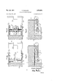
- Fig. 1 is a side elevation of a complete bar with its opposite ends engaged in parallel vertical supports.
- the connecting device, at the right-hand end is shown in axial section.
- the mid-portion of the bar is broken away to shorten the View and permit use of a large scale.
- Fig. 2 is a section, similar to the right-hand end of Fig. '1, but showing how the hooked end is disengaged.
- Fig. 3 is a perspective view of one of the con- 2 necting devices. The swinging member is shown in the position it assumes when engaged. The bolt is shown retracted.
- Fig. 4 is a plan view of the swinging hookended member.
- Fig. 5 is a view on a reduced scale-as compared with Figs. 1, 2 and 4, showing a fragment of the perforated wall plate with beam-supporting members inserted.
- Figs. 6 and 7 are respectively horizontal and vertical sections of a first modification in which the swinging member is latched to the bar.
- Figs. 8 and 9 are respectively horizontal and vertical sections of a second modification using a different type of latch.
- the beam member is generally indicated by the numeral ll.
- the beam is of a composite construction comprising a pressed steel shell I2 to which are-bolted wooden filler pieces I 3. So far as the present disclosure is concerned, the significant fact is that the metal housings for the end attaching means which are generally indicated by the numeral M are welded to the steel shell l2.
- Each housing comprises a steel member l5 which is welded to the core l2 and which has down-turned flanges l6 formed with elongated apertures H.
- the apertures I! receive trunnions 18 on the end of the swinging member l9.
- the openings l1 and trunnions l8 afford a swinging-and-slidlng connection of the pinand-slot type.
- the mounting allows the member I9 to swing on a horizontal axis between a pendant disengaged position, and a horizontal position in which it engages portions of the housing l4.
- the swinging member l9 has a hook-shaped end.
- a heavy boss 24 Formed on the upper face of the member I9 is a heavy boss 24.
- the boss 24 enters a notch 25 (see Fig. 3) which is formed in a part of the housing M to receive and laterally confine it.
- boss 24 engages the notch 25 and prevents transverse motion of the part [9 in the direction of the axis of the trunnio'ns 18.
- the boss 24 performs a second function which is clearly illustrated in Fig. 1. As there shown it is close to the inner face of the plate 23 and limits the entrance of the hooked ends 2 I. In conjunction with the hooked ends it prevents lateral cocking of the member .5 9 relatively to the correspondingplate 23.
- the boss 2t also performs a third function which is clearly illustrated in Fig. 2.
- the corner of the boss 24 strikes the inner face of the plate 23 and causes wi thdraw'al of' -the hooked ends from the plate.
- the member 24 acts as a sort of card and in another sense it acts as a fulcrum. It mightiuncti'ori.
- the member 32 may be shifted laterally in either direction far enough to clear the lug 3i. Thereupon the member H9 is free to swing downward and the member 3
- Figs. 8 and 9 The construction shown in Figs. 8 and 9 is quite similar to that shown in Figs. 6 and 7. I rtitheseeviewssparts that are generally similar to those shown in Fig. 1 are given the same reference numerals increased by 200.
- 9 is cut away in its mid-portion as madeof-a: bolt-26svhichwhen projected as shown in- Fig.-. 1 entersa third one. of the apertures. in plate 23.
- the housing M includes ani-in'verted U-shaped' portion 21.
- the bolt26 is guided-inholes formed in the portion.
- Z'Land may be shifted toand-fromitsengagingposition byes-finger piece-28;
- AlugZS welded'tothc top of plate i5 serves as astop to hold .thebolt 26 selectively inits engaged and-in its disengaged positions:
- the bolt-is freed by liftirigthe finger pieceifl far enough toclear the lug 28; is shifted longitudinally and is then locked by. swinging thefingerpiece downward so that it engages one ortheother side of thelug' 25.
- a sleeve 33 which is-slidable on'a cross pin 34 and is centered there-: on: by; twocoil compression springs 35-. These 3'lrwhich projects into this space.
- the trunnion 2E8 is continuous and supports an axially shiftable sleeve 38.
- 'Ihissleeve carries a disk.39.having a notch. 41 dimensioned to straddlethe lug 31 and having-onesecant face 42-which is adjacent tothe face of the shell 2l5, as best shown in Fig. 9..
- the member39 is centered by two light springs 43-verymuchas.
- the sleeve 33 of Fig. 6 is centered by the. springs 35. It. can be moved ineither direction-toclear the lug 3].
- Means for locking the end of a beam in abutting relation toan aperturedplate-like support to which the beam is substantially perpendicular comprising in combination with the beam; means carried by the beam and affording a hinge axis transverse'to the beam and adjacent to but spaced from said end thereof; aconnecting member hingedonsaid axis and having a hook-shaped end adapted to enter an aperture in the support, as said connecting member is swung about said axis toward a beam-supportingposition in which said member is in lateral contact with the beam adjacent said end thereof; and a hook extracting lug carried by said connecting member and serving to engage and react against said support to cause withdrawal of said hook-shaped end as the connecting member swings away from said beam supportin position.
- Means for locking the end of a beam in abutting relation to an apertured plate-like support to. which the beam is substantially perpendicular comprising, in combination with the beam; a connecting member having a hookshaped. end adapted to enter an aperture in said support as said connecting member is swung towards lateral contact with an end portion of thebeam about an axis spaced from the end of and transverse to the beam; means affording a swinging and sliding connection between the other end of said connecting member and a part of the beam spaced from the end thereof, said connection aifordingthe transverse axis aforesaid, and including slot means permitting motion of said connecting member in the direction of the length of the beam; an extractinglug carried by said connecting member in position to engage said support and forcibly withdraw the hook-shaped end from said aperture asan incident to reverse swinging motion of saidmemher; and-- alining means affording engagement between the connecting member and the beam, at least when said hook-shaped end is engaged in said support, said alining
- Means for locking the end of a beam in abutting relation to an apertured plate-like support to which the beam is substantially perpendicular comprising, in combination with the beam; a connecting member having a hookshaped end adapted to enter an aperture in said support as said connecting member is swung to- I length of the beam; an extracting lug carried by :2-
- said connecting member in position to engage said support and forcibly withdraw the hookshaped end from said aperture as an incident to reverse swinging motion of said connecting member; alining means afiording engagement between the member and the beam, at least when said hook-shaped end is engaged in an aperture in said support, said alining means comprising a lug and slot, one extending longitudinally of the beam and the other extending longitudinally of said connecting member and so formed asto have lateral inter-engagement and end clearance to resist lateral and permit longitudinal relative motion; and secondary locking means shiitable to a position in which it prevents said reverse swinging motion of the connecting member, at least when said hook-shaped end is engaged in an aperture in the support.
- the secondary locking means is a shiftable stop guided on and supported by the beam and adapted in one position to engage a side of said connecting member so as to resist swinging motion thereof away from the beam while permitting the longitudinal motion afforded by said swinging-and-sliding connection.
Description
Nov. 20, 1951 F. FAHLAND 2,575,550
CARGO -SUPPORTING CROSSBAR Filed June 29, 1950 2 Sl-IEETS-SHEET 1 Pic-3.1
3nventor Fr g-ink Fahl and PJLJM Gttornegs Nov. 20, 1951 F. FAHLAND CARGO-SUPPORTING CROSSBAR Filed June 29, 1950 2 Sl-IEETS--SHEET 2 Snventor Frank Fahland mNH G mm D E NAN HNN
w ww
(Ittornegs Patented Nov. 20, 1951 UNITED STATES PATENT OFFICE 8 Claims.
This invention relates to load-supporting and load-bracing elements for use in transport vehicles such as freight cars, vans, ships and the like, and affords a simplified and improved construction for the attaching fittings for bars of the type shown in my Patents 2,440,437, April 2'7, 1948, and 2,476,362, July 19, 1949.
These prior patents disclose hook-ended members which are hinged to the lower side of the beam on transverse axes and can be swung upward into supporting engagement with the end of the beam. During such swinging motion hooked ends formed on said members enter selected apertures in an apertured, plate-like vertical support and engage the rear surface of the support so as to resist horizontal withdrawal. A novel feature of the present invention is the provision of means to extract the hooked ends forcibly as-an incident to reverse swinging of the hook-ended members, such as occurs when the beam is dismounted.
In Patent 2,240,437 the hook-ended member swings on a pin-and-slot connection which accommodates variations in support-spacing and requires the use of secondary alining means. A second novel feature of the present invention is an arrangement such that the secondary alining means and the hook extracting means are combined in a single part.
Some sort of secondary locking means is desirable and even necessary. The embodiments shown in the Fahland patents make use of a bolt which is projected from the end of the beam and enters an aperture in the support. This is the simplestand strongest arrangement, and is preferred to those arrangements previously used in which the swinging member was pinned or latched to the bar so that it cannot swing away therefrom. Examples of spring latches for this purpose will be illustrated. These examples disclose distinct types of strong and simple construction which are readily manipulated. Also they serve to illustrate the general availability of the improved hook-ended connector.
In the drawings:
Fig. 1 is a side elevation of a complete bar with its opposite ends engaged in parallel vertical supports. The connecting device, at the right-hand end is shown in axial section. The mid-portion of the bar is broken away to shorten the View and permit use of a large scale.
Fig. 2 is a section, similar to the right-hand end of Fig. '1, but showing how the hooked end is disengaged.
Fig. 3 is a perspective view of one of the con- 2 necting devices. The swinging member is shown in the position it assumes when engaged. The bolt is shown retracted.
Fig. 4 is a plan view of the swinging hookended member. I
Fig. 5 is a view on a reduced scale-as compared with Figs. 1, 2 and 4, showing a fragment of the perforated wall plate with beam-supporting members inserted. v
Figs. 6 and 7 are respectively horizontal and vertical sections of a first modification in which the swinging member is latched to the bar.
Figs. 8 and 9 are respectively horizontal and vertical sections of a second modification using a different type of latch.
Refer first to Figs. 1-5 inclusive.
The beam member is generally indicated by the numeral ll. As is the case with the beams in my two patents above identified, the beam is of a composite construction comprising a pressed steel shell I2 to which are-bolted wooden filler pieces I 3. So far as the present disclosure is concerned, the significant fact is that the metal housings for the end attaching means which are generally indicated by the numeral M are welded to the steel shell l2.
Each housing comprises a steel member l5 which is welded to the core l2 and which has down-turned flanges l6 formed with elongated apertures H. The apertures I! receive trunnions 18 on the end of the swinging member l9. Thus, the openings l1 and trunnions l8 afford a swinging-and-slidlng connection of the pinand-slot type. The mounting allows the member I9 to swing on a horizontal axis between a pendant disengaged position, and a horizontal position in which it engages portions of the housing l4. The swinging member l9 has a hook-shaped end. In the example illustrated there are two hooked portions 2| spaced apart so that the member l9 will engage two of the apertures 22 formed in the corresponding supporting plate 23 (see Fig. 5). It is probably unnecessary to state that plates such as 23 are used as linings for freight cars and the apertures are provided to offer opportunity for the attachment of horizontal load-sustaining beams such as the beam H.
Formed on the upper face of the member I9 is a heavy boss 24. When the member I9 is in beam-supporting position, the boss 24 enters a notch 25 (see Fig. 3) which is formed in a part of the housing M to receive and laterally confine it. Thus, when themember I9 is in beamsupporting position (consider Figs. 1 and 3), the
The boss 24 performs a second function which is clearly illustrated in Fig. 1. As there shown it is close to the inner face of the plate 23 and limits the entrance of the hooked ends 2 I. In conjunction with the hooked ends it prevents lateral cocking of the member .5 9 relatively to the correspondingplate 23.
The boss 2t also performs a third function which is clearly illustrated in Fig. 2. When the end of beam H is lifted for the purpose of dieengaging the swinging member iii-from the-:plate" 23, the corner of the boss 24 strikes the inner face of the plate 23 and causes wi thdraw'al of' -the hooked ends from the plate. Inone-sense the member 24 acts as a sort of card and in another sense it acts as a fulcrum. It mightiuncti'ori.
are mounted under virtually no stress and normally merely center the member 32.
As will be apparent from an inspection of Fig. 6, the member 32 may be shifted laterally in either direction far enough to clear the lug 3i. Thereupon the member H9 is free to swing downward and the member 3| will hold the member 32 displaced. Restoration of the member I I?! to its upper position (see Fig. 7) will result in theirestqration of the member 32 to itsnormal position;
The construction shown in Figs. 8 and 9 is quite similar to that shown in Figs. 6 and 7. I rtitheseeviewssparts that are generally similar to those shown in Fig. 1 are given the same reference numerals increased by 200.
Member 2|9 is cut away in its mid-portion as madeof-a: bolt-26svhichwhen projected as shown in- Fig.-. 1 entersa third one. of the apertures. in plate 23.
'Eoguide the bolt 26, the housing M includes ani-in'verted U-shaped' portion 21. The bolt26 is guided-inholes formed in the portion. Z'Land may be shifted toand-fromitsengagingposition byes-finger piece-28; AlugZS welded'tothc top of plate i5 serves as astop to hold .thebolt 26 selectively inits engaged and-in its disengaged positions: The bolt-is freed by liftirigthe finger pieceifl far enough toclear the lug 28; is shifted longitudinally and is then locked by. swinging thefingerpiece downward so that it engages one ortheother side of thelug' 25.
Bolt ZS-prevents. riseof the end of the beam l l and consequently.makesitimpossible for the swinging member. 19- to move away from the lower face of the beam. As a consequence, the boss 24is maintained in engagement with the notch-25 and. the hook-shaped ends 2|, by their engagement behind the plate 23, prevent the horizontal withdrawal of the member I 9 from the plate- The pin-and-.slot connection l1, l8 accommodates errors in the spacing of the lining plates 23' which may result from various. causes.
The construction above described is the preferred one but the advantagesof the invention can also be had in a type of construction in which the swinging member is latched. to the beam so that it cannot move away from the end of the beam. In such a construction entire reliance is placed on the swinging member l9'andits two hooked ends 2!.
In the first modification shown in Figs: 6 and 7 parts similar to parts in Fig. l are" given the same reference numerals increased by 100. The member H8 is confined between the flanges HS andhastrunnions Hi5 engaging the elongated slotsl i'L. Member. H9 is formed with an extension 31 which extends beyondthe trunnions H3 in a direction away from the hooked end I24. Themember H5 is lockedinto engaging positionshown-in Figs. 6 and-7 by an. L-shaped bar 32 which enters between the-extension. 3i. and a portion of the housing H5 (see Fig. 7). The L-shaped member 32 is fixed. on a sleeve 33 which is-slidable on'a cross pin 34 and is centered there-: on: by; twocoil compression springs 35-. These 3'lrwhich projects into this space. The trunnion 2E8 is continuous and supports an axially shiftable sleeve 38. 'Ihissleevecarries a disk.39.having a notch. 41 dimensioned to straddlethe lug 31 and having-onesecant face 42-which is adjacent tothe face of the shell 2l5, as best shown in Fig. 9.. The member39 is centered by two light springs 43-verymuchas. the sleeve 33 of Fig. 6 is centered by the. springs 35. It. can be moved ineither direction-toclear the lug 3].
These arrangements have the advantage that the. members32and 39 can be shifted in either direction to release the device and lie wholly -within the dimensional limits v.of'the beam; As
a consequence; they, interfere with nothing and are readily accessible for manipulation.
I. claim:
1. Means for locking the end of a beam in abutting relation toan aperturedplate-like support to which the beam is substantially perpendicular, comprising in combination with the beam; means carried by the beam and affording a hinge axis transverse'to the beam and adjacent to but spaced from said end thereof; aconnecting member hingedonsaid axis and having a hook-shaped end adapted to enter an aperture in the support, as said connecting member is swung about said axis toward a beam-supportingposition in which said member is in lateral contact with the beam adjacent said end thereof; and a hook extracting lug carried by said connecting member and serving to engage and react against said support to cause withdrawal of said hook-shaped end as the connecting member swings away from said beam supportin position.
2.. Means for locking the end of a beam in abutting relation to an apertured plate-like support to. which the beam is substantially perpendicular comprising, in combination with the beam; a connecting member having a hookshaped. end adapted to enter an aperture in said support as said connecting member is swung towards lateral contact with an end portion of thebeam about an axis spaced from the end of and transverse to the beam; means affording a swinging and sliding connection between the other end of said connecting member and a part of the beam spaced from the end thereof, said connection aifordingthe transverse axis aforesaid, and including slot means permitting motion of said connecting member in the direction of the length of the beam; an extractinglug carried by said connecting member in position to engage said support and forcibly withdraw the hook-shaped end from said aperture asan incident to reverse swinging motion of saidmemher; and-- alining means affording engagement between the connecting member and the beam, at least when said hook-shaped end is engaged in said support, said alining means comprising a lug and slot, one extending longitudinally of the beam and the other extending longitudinally of said member, the lug and slot being so formed as to have lateral inter-engagement and end clearance to resist lateral and permit longitudinal relative motion.
3. The combination defined in claim 2 in which the extracting lug serves also as said alining lug, the alining slot being formed in a lateral portion of the end part of the beam.
4. Means for locking the end of a beam in abutting relation to an apertured plate-like support to which the beam is substantially perpendicular comprising, in combination with the beam; a connecting member having a hookshaped end adapted to enter an aperture in said support as said connecting member is swung to- I length of the beam; an extracting lug carried by :2-
said connecting member in position to engage said support and forcibly withdraw the hookshaped end from said aperture as an incident to reverse swinging motion of said connecting member; alining means afiording engagement between the member and the beam, at least when said hook-shaped end is engaged in an aperture in said support, said alining means comprising a lug and slot, one extending longitudinally of the beam and the other extending longitudinally of said connecting member and so formed asto have lateral inter-engagement and end clearance to resist lateral and permit longitudinal relative motion; and secondary locking means shiitable to a position in which it prevents said reverse swinging motion of the connecting member, at least when said hook-shaped end is engaged in an aperture in the support.
5. The combination defined in claim 4 in which the extracting lug serves also as said alining lug, the alining slot being formed in a lateral portion of the end part of the beam.
6; The combination defined in claim 4 in which the extracting lug serves also as said alining lug, the alining slot being formed in a lateral portion of the end part of the beam, said lug being so located and dimensioned that it serves also to limit the entrance of the hook-shaped end of the member into openings in said support.
7. The combination defined in claim 4 in which said secondary locking means is guided on and supported by the beam and engages in an aperture in said support.
8. The combination defined in claim 4 in which the secondary locking means is a shiftable stop guided on and supported by the beam and adapted in one position to engage a side of said connecting member so as to resist swinging motion thereof away from the beam while permitting the longitudinal motion afforded by said swinging-and-sliding connection.
FRANK FAHLAND.
No references cited.
Priority Applications (1)
| Application Number | Priority Date | Filing Date | Title |
|---|---|---|---|
| US171059A US2575550A (en) | 1950-06-29 | 1950-06-29 | Cargo-suporting crossbar |
Applications Claiming Priority (1)
| Application Number | Priority Date | Filing Date | Title |
|---|---|---|---|
| US171059A US2575550A (en) | 1950-06-29 | 1950-06-29 | Cargo-suporting crossbar |
Publications (1)
| Publication Number | Publication Date |
|---|---|
| US2575550A true US2575550A (en) | 1951-11-20 |
Family
ID=22622332
Family Applications (1)
| Application Number | Title | Priority Date | Filing Date |
|---|---|---|---|
| US171059A Expired - Lifetime US2575550A (en) | 1950-06-29 | 1950-06-29 | Cargo-suporting crossbar |
Country Status (1)
| Country | Link |
|---|---|
| US (1) | US2575550A (en) |
Cited By (10)
| Publication number | Priority date | Publication date | Assignee | Title |
|---|---|---|---|---|
| US2834304A (en) * | 1954-09-21 | 1958-05-13 | Evans Prod Co | Freight loading apparatus |
| US2879722A (en) * | 1956-03-09 | 1959-03-31 | Evans Prod Co | Cross bar |
| US2935033A (en) * | 1955-01-07 | 1960-05-03 | Evans Prod Co | Freight supporting bar |
| US2947262A (en) * | 1954-11-03 | 1960-08-02 | Evans Prod Co | Portable trolley track and trolley assembly |
| US2963992A (en) * | 1956-09-27 | 1960-12-13 | David D Wood | Freight bracing structure |
| US3137248A (en) * | 1957-11-15 | 1964-06-16 | Sparton Corp | Cross member assembly |
| US3185110A (en) * | 1962-08-24 | 1965-05-25 | Evans Prod Co | Freight bracing apparatus |
| US3202111A (en) * | 1962-07-03 | 1965-08-24 | Evans Prod Co | Freight bracing apparatus |
| US3774939A (en) * | 1971-09-16 | 1973-11-27 | Union Pacific Railroad Co | Load restraining crossbar |
| WO2017189486A1 (en) * | 2016-04-28 | 2017-11-02 | Bradford Company | Container having at least one lockable crossbar assembly movable along tracks |
-
1950
- 1950-06-29 US US171059A patent/US2575550A/en not_active Expired - Lifetime
Non-Patent Citations (1)
| Title |
|---|
| None * |
Cited By (10)
| Publication number | Priority date | Publication date | Assignee | Title |
|---|---|---|---|---|
| US2834304A (en) * | 1954-09-21 | 1958-05-13 | Evans Prod Co | Freight loading apparatus |
| US2947262A (en) * | 1954-11-03 | 1960-08-02 | Evans Prod Co | Portable trolley track and trolley assembly |
| US2935033A (en) * | 1955-01-07 | 1960-05-03 | Evans Prod Co | Freight supporting bar |
| US2879722A (en) * | 1956-03-09 | 1959-03-31 | Evans Prod Co | Cross bar |
| US2963992A (en) * | 1956-09-27 | 1960-12-13 | David D Wood | Freight bracing structure |
| US3137248A (en) * | 1957-11-15 | 1964-06-16 | Sparton Corp | Cross member assembly |
| US3202111A (en) * | 1962-07-03 | 1965-08-24 | Evans Prod Co | Freight bracing apparatus |
| US3185110A (en) * | 1962-08-24 | 1965-05-25 | Evans Prod Co | Freight bracing apparatus |
| US3774939A (en) * | 1971-09-16 | 1973-11-27 | Union Pacific Railroad Co | Load restraining crossbar |
| WO2017189486A1 (en) * | 2016-04-28 | 2017-11-02 | Bradford Company | Container having at least one lockable crossbar assembly movable along tracks |
Similar Documents
| Publication | Publication Date | Title |
|---|---|---|
| US2575550A (en) | Cargo-suporting crossbar | |
| US3125035A (en) | Freight handling means | |
| US2980037A (en) | Self-locking bar attachment | |
| US3159111A (en) | Container attachment device for railway cars | |
| US20050258330A1 (en) | Latch device for securing cargo containers together and/or to vehicle decks | |
| US3799070A (en) | Freight retaining bar | |
| US4091745A (en) | Cross bar end fitting | |
| US3071086A (en) | Freight bracing apparatus | |
| US4163425A (en) | Load anchoring systems for flatbed | |
| US2911925A (en) | Movable bulkhead | |
| US3632145A (en) | Semiautomatic kingpin locking mechanism | |
| US3774939A (en) | Load restraining crossbar | |
| US3782295A (en) | Cargo restraining bar | |
| USRE24118E (en) | Cross bar support for vehicles | |
| US3130690A (en) | Freight loading apparatus | |
| US3768857A (en) | Disappearing twist lock assembly | |
| US3630155A (en) | Railroad container bracket structure | |
| US3486468A (en) | Lading separating means | |
| US3626868A (en) | Transportation system and components thereof | |
| US3104623A (en) | Railway hopper car pivoted closure latching mechanism | |
| US3004500A (en) | Railway flat car bridging plate | |
| US3431015A (en) | Lading supporting and separating means | |
| US3104017A (en) | Carrier assembly for rotary coupler | |
| US3262402A (en) | Collapsible hitch | |
| US3143083A (en) | Fifth wheel stand |