US2575461A - Adjustable scaffold base - Google Patents
Adjustable scaffold base Download PDFInfo
- Publication number
- US2575461A US2575461A US697605A US69760546A US2575461A US 2575461 A US2575461 A US 2575461A US 697605 A US697605 A US 697605A US 69760546 A US69760546 A US 69760546A US 2575461 A US2575461 A US 2575461A
- Authority
- US
- United States
- Prior art keywords
- legs
- scaffold
- substructure
- pair
- cross member
- Prior art date
- Legal status (The legal status is an assumption and is not a legal conclusion. Google has not performed a legal analysis and makes no representation as to the accuracy of the status listed.)
- Expired - Lifetime
Links
Images


Classifications
-
- E—FIXED CONSTRUCTIONS
- E04—BUILDING
- E04G—SCAFFOLDING; FORMS; SHUTTERING; BUILDING IMPLEMENTS OR AIDS, OR THEIR USE; HANDLING BUILDING MATERIALS ON THE SITE; REPAIRING, BREAKING-UP OR OTHER WORK ON EXISTING BUILDINGS
- E04G1/00—Scaffolds primarily resting on the ground
- E04G1/24—Scaffolds primarily resting on the ground comprising essentially special base constructions; comprising essentially special ground-engaging parts, e.g. inclined struts, wheels
Definitions
- the scaffold legs In many cases the ground or foundation on which a scaffold rests is uneven and, in order to provide horizontal working platforms, the scaffold legs must be adjusted vertically to compensate for the unevenness. Such adjustments have been accomplished in various ways, such as by using telescoping legs or by adding short adapter lengths to the lower ends of the legs. In either case the scaffold may tend to be unsteady and to wobble if the legs are lengthened very much.
- a major disadvantage of prior scaffolds arises when the ground slopes upwardly away from the wall along which the scaffold extends.
- the scaffold legs next to the wall can be lengthened or blocked up to level the scaffold, but that raises the lowest stage or working platform that much farther from the ground level at the wall.
- a workman standing on the ground then no longer may be able to work up to the first platform without standing on an improvised support.
- the end panels of such scaffolds are of a height that just allows an average workman standing on a platform or surface even with the bottom of the panels to work convenientlyup to the next platform, a distance generally of about four and a half or five feet.
- a scaffold substructure is formed from a pair of spaced, parallel end frames connected together by braces that hold them upright to form a stablestructure.
- Each of the frames includes a pair of spaced, parallel legs which are connected together below their upper ends by means of a horizontal cross member which is adapted to support the planks of a working platform.
- the cross members also are .designed for supporting a scaffold.
- the cross members are connected to the legs by members, preferably collars, that are adjustable axially of the legs so that the cross members can be moved up and down on the legs, or the legs can be adjusted vertically relative to one another to compensate for uneven ground on which the substructure may rest.
- the collar may be provided with transverse 6 Claims. (01. 304-2.)
- Figs. 1 and 2 openingsa'dapted toregister with different verticallyspaced openings'in the legs, and pins can the collar-in place.
- cross' braces connect the cross members and inbe inserted in the registering openings to hold Most suitably, horizontal clined braces connect the legs.
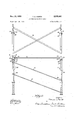
- the ends of the inclinedbraces may be connected to the legsat any of the leg openings so that when a vertical "adjustment of the legs is-made, the position of which Fig. 1 is an end 'view of the substructure showing a scaifoldfunit supported thereon; Fig. 2 a side View of the same assembly; Fig. 3 a plan view of the substructure; and'Figs. 4 and 5 enlarged sections along lines IV-IV and VV of "Figs. 1 and 2, respectively.
- the substructure l comp'risesa pair of spaced, parallel end frames 2 5 and3 each of which has a pair of vertical legs 4 and-5 connected together by a horizontal cross member 6.
- the legs preferably are formed from pipe,- and the cross member from an angle bar which is adapted'to support planking (not shown) on its upper surface inorder to form a stage or working platform. Beneath'the cross member the legs are connected by an inclined brace l.
- Horizontal braces 8, Fig. 3 extend diagonally between the cross members of the end frames to maintain them-parallel and to help keep them square.
- braces 8 are con- 'nected to the horizontal crossmembers by downwardly projecting pins 9 formed on the ends of the braces and fitting into vertical sleeves l0 fwelded'tothe-inside of the cross members.
- braces 8 are positioned on the lower-portions of the cross members so that when pins 9 are inserted therein the tops of braces 8 will lie in a planeat least as low as th upper surface'of the cross membersinorder'toavoid interfering with .the Workin per orm;
- the end frames also are connected together by .inclined braces i I attached to their legs.
- the substructure can be extended to any desired length by adding more end frames and the necessary braces.
- Thev substructure is designed for I suppoftinga scaffold.
- One scaffold unit shown mounted on the substructure Figs. 1 and 2, can be of anystandard type known to this art. This unit is formed from spaced apart prefabricated end frames each havingtubular legs [2 connected by suitable braces, and braces [3 connecting the endframes to form a rigid structure.
- each of said substructure frames including a pair of spaced parallel legs independently adjustable vertically relative to each other, a horizontal cross member between the substructure legs adapted to support a working platform, means adjustable axially of the said substructure legs for connecting the ends of said cross members thereto a material distance below the upper ends of the legs, the legs of each end frame of said scaffold resting on the cross member of each end frame of said substructure whereby said scaifold is supported, vertical plugs projecting upwardly from the ends of each cross member and adapted to project into the legs of said scaffold, a yoke straddling the upper end of each substructure leg, and means pivotally connecting the yoke to that leg to permit the free end of the yoke to be swung to a position above the underlying cross member, said free end of the yoke being bifurcated to adapt it to straddle an adjacent scaffold leg supported by said cross members.
- a scaffold substructure for use in supporting a scaffold formed of a pair of spaced parallel end frames each having a pair of spaced parallel legs, said substructure comprising a pair of spaced parallel end frames, and braces connecting said frames for holding them upright, each of said substructure frames including a pair of spaced parallel legs independently adjustable vertically relative to each other, a horizontal cross member between the legs adapted to support a working platform, said cross members having a flat upper surface, collars secured to the opposite ends of each cross member and slidably receiving the legs, each of said legs being provided with vertically spaced openings, said collars being provided with transverse openings, means adapted to be inserted in said collar openings and any of said leg openings to lock the cross members on the substructure at different levels, the legs of each end frame of said scaffold resting on the cross member of each end frame of said substructure whereby said scaifold is supported, vertical plugs mounted on said flat surface of each cross member near its ends, said plugs projecting upwardly and being adapted to project into the legs of
- a scaffold substructure for use in supporting a scaffold formed of a pair of spaced parallel end frames each having a pair of spaced parallel legs, said substructure comprising a pair of spaced parallel end frames, and braces connecting said frames for holding them upright, each of said substructure frames including a pair of spaced parallel legs independently adjustable vertically relative to each other, a horizontal cross member between the legs adapted to support a working platform, means adjustable axially of said substructure legs for connecting the adjacent ends of said cross members thereto, the legs of each end frame of said scafiold resting on the cross member of each end frame of said substructure whereby said scaffold is supported, means between said pair of legs projecting upwardly from each cross member and adapted to receive the feet of the scaffold and keep them from moving laterally, clamping means connected to said frame and adapted to grip the legs of said scaffold. and hold the scaffold on said cross members.
- a scaffold and a scaffold substructure comprising a pair of spaced parallel end frames and braces connecting said frames for holding them upright, each of said end frames including a pair of spaced parallel legs and a cross member between the legs; and said substructure comprising a pair of spaced parallel end frames, and braces connecting said frames for holding them upright, each of said substructure end frames including a pair of spaced parallel legs independently adjustable vertically relative to each other, a horizontal cross member between the legs adapted to support a working platform, means adjustable axially of said legs for connecting the ends of said cross member thereto, the legs of each end frame of said scaffold resting on the cross member of each end frame of said substructure whereby said scaffold is supported, and means mounted on each of said substructure cross members for receiving said scaffold legs and keeping them from moving laterally.
- a scaffold and a scaffold substructure comprising a pair of spaced parallel end frames and braces connecting said frames for holding them upright, each 3, of said end frames including a pair of spaced parallel legs and a cross member between the legs; and said substructure comprising a pair of spaced parallel end frames, and braces connecting said frames for holding them upright, each of said substructure end frames including a pair of spaced parallel legs independently adjustable vertically relative to each other, a horizontal cross member between the legs adapted to support a working platform, means adjustable axially of said legs for connecting the ends of said cross members thereto a material distance below the upper ends of the legs, the legs of each end frame of said scaffold resting on the cross member of each end frame of said substructure Whereby said scaffold is supported, means between said pair of legs projecting upwardly from said substructure cross members for receiving said scaffold legs and keeping them from moving laterally, and clamping means pivotally connected to the upper end portions of the substructure legs for gripping the scaffold legs and holding the scaffold on said substructure end frames.
Description
1951 T. c. NORTH ADJUSTABLE SCAFFOLD BASE 5 Sheets-Sheet 1 I Filed Sept. 18, 1946 1 INVENTOR.
. 8x W @n;a%-4J-Mv MM 24.. arrokmsxs.
T. C. NORTH ADJUSTABLE SCAFFOLD BASE Nov. 20, 1951 3 Sheets-Sheet 2 Filed Sept. 18, 1946 l J V INVENTOR.
TT /eA/Ers.
MTNESSES. D. 0894*,
1951 T. c. NORTH ADJUSTABLE SCAF'FOLD BASE 3 Sheets-Sheet 3 Filed Sept. 18, 1946 INVENTOR. 4M 121M rA/esss 5. BY 25 W1 wrfldwm a r role/vs Ys Patented Nov. 20, 1951 UNITED STATES PATENT "OFFICE ADJUSTABLE SCAFFOLD BASE I Thomas C. North, Zelienople, Pa., assignor to Universal Fittings & Scaffolding Company, Zelienople, 2a., a corporation of Pennsylvania Application September 18,1946, Serial No. 697,605
ticular, to a scafiold base or substructure for supporting prefabricated units of scaffolding.
In many cases the ground or foundation on which a scaffold rests is uneven and, in order to provide horizontal working platforms, the scaffold legs must be adjusted vertically to compensate for the unevenness. Such adjustments have been accomplished in various ways, such as by using telescoping legs or by adding short adapter lengths to the lower ends of the legs. In either case the scaffold may tend to be unsteady and to wobble if the legs are lengthened very much.
A major disadvantage of prior scaffolds arises when the ground slopes upwardly away from the wall along which the scaffold extends. The scaffold legs next to the wall can be lengthened or blocked up to level the scaffold, but that raises the lowest stage or working platform that much farther from the ground level at the wall. A workman standing on the ground then no longer may be able to work up to the first platform without standing on an improvised support. This is because the end panels of such scaffolds are of a height that just allows an average workman standing on a platform or surface even with the bottom of the panels to work convenientlyup to the next platform, a distance generally of about four and a half or five feet.
It is among the objects of this invention to provide a scaffold substructure which makes vertical adjustment of the scaffold legs unnecessary, which is formed to support a working platform at any desired level above the ground, which has strong and rigid vertically adjustable legs, and which can be quickly and securely fastened to a scaffold mounted thereon.
In accordance with this invention a scaffold substructure is formed from a pair of spaced, parallel end frames connected together by braces that hold them upright to form a stablestructure. Each of the frames includes a pair of spaced, parallel legs which are connected together below their upper ends by means of a horizontal cross member which is adapted to support the planks of a working platform. The cross members also are .designed for supporting a scaffold. The cross members are connected to the legs by members, preferably collars, that are adjustable axially of the legs so that the cross members can be moved up and down on the legs, or the legs can be adjusted vertically relative to one another to compensate for uneven ground on which the substructure may rest.
The collar may be provided with transverse 6 Claims. (01. 304-2.)
. openingsa'dapted toregister with different verticallyspaced openings'in the legs, and pins can the collar-in place. cross' braces connect the cross members and inbe inserted in the registering openings to hold Most suitably, horizontal clined braces connect the legs. The ends of the inclinedbraces may be connected to the legsat any of the leg openings so that when a vertical "adjustment of the legs is-made, the position of which Fig. 1 is an end 'view of the substructure showing a scaifoldfunit supported thereon; Fig. 2 a side View of the same assembly; Fig. 3 a plan view of the substructure; and'Figs. 4 and 5 enlarged sections along lines IV-IV and VV of "Figs. 1 and 2, respectively.
- Referring to the drawings, the substructure l comp'risesa pair of spaced, parallel end frames 2 5 and3 each of which has a pair of vertical legs 4 and-5 connected together by a horizontal cross member 6. The legs preferably are formed from pipe,- and the cross member from an angle bar which is adapted'to support planking (not shown) on its upper surface inorder to form a stage or working platform. Beneath'the cross member the legs are connected by an inclined brace l.
sleeves are positioned on the lower-portions of the cross members so that when pins 9 are inserted therein the tops of braces 8 will lie in a planeat least as low as th upper surface'of the cross membersinorder'toavoid interfering with .the Workin per orm; The end frames also are connected together by .inclined braces i I attached to their legs. The substructure can be extended to any desired length by adding more end frames and the necessary braces.
Thev substructure, as stated, is designed for I suppoftinga scaffold. One scaffold unit, shown mounted on the substructure Figs. 1 and 2, can be of anystandard type known to this art. This unit is formed from spaced apart prefabricated end frames each havingtubular legs [2 connected by suitable braces, and braces [3 connecting the endframes to form a rigid structure.
frames for holding them upright, each of said substructure frames including a pair of spaced parallel legs independently adjustable vertically relative to each other, a horizontal cross member between the substructure legs adapted to support a working platform, means adjustable axially of the said substructure legs for connecting the ends of said cross members thereto a material distance below the upper ends of the legs, the legs of each end frame of said scaffold resting on the cross member of each end frame of said substructure whereby said scaifold is supported, vertical plugs projecting upwardly from the ends of each cross member and adapted to project into the legs of said scaffold, a yoke straddling the upper end of each substructure leg, and means pivotally connecting the yoke to that leg to permit the free end of the yoke to be swung to a position above the underlying cross member, said free end of the yoke being bifurcated to adapt it to straddle an adjacent scaffold leg supported by said cross members.
3. A scaffold substructure for use in supporting a scaffold formed of a pair of spaced parallel end frames each having a pair of spaced parallel legs, said substructure comprising a pair of spaced parallel end frames, and braces connecting said frames for holding them upright, each of said substructure frames including a pair of spaced parallel legs independently adjustable vertically relative to each other, a horizontal cross member between the legs adapted to support a working platform, said cross members having a flat upper surface, collars secured to the opposite ends of each cross member and slidably receiving the legs, each of said legs being provided with vertically spaced openings, said collars being provided with transverse openings, means adapted to be inserted in said collar openings and any of said leg openings to lock the cross members on the substructure at different levels, the legs of each end frame of said scaffold resting on the cross member of each end frame of said substructure whereby said scaifold is supported, vertical plugs mounted on said flat surface of each cross member near its ends, said plugs projecting upwardly and being adapted to project into the legs of said scaffold resting on said flat surface, and clamping means pivotally connected to the upper end of said substructure legs and adapted to be swung into clamping engagement with an adjacent scaffold leg supported by said cross members.
4. A scaffold substructure for use in supporting a scaffold formed of a pair of spaced parallel end frames each having a pair of spaced parallel legs, said substructure comprising a pair of spaced parallel end frames, and braces connecting said frames for holding them upright, each of said substructure frames including a pair of spaced parallel legs independently adjustable vertically relative to each other, a horizontal cross member between the legs adapted to support a working platform, means adjustable axially of said substructure legs for connecting the adjacent ends of said cross members thereto, the legs of each end frame of said scafiold resting on the cross member of each end frame of said substructure whereby said scaffold is supported, means between said pair of legs projecting upwardly from each cross member and adapted to receive the feet of the scaffold and keep them from moving laterally, clamping means connected to said frame and adapted to grip the legs of said scaffold. and hold the scaffold on said cross members.
5. The combination of a scaffold and a scaffold substructure, said scaffold comprising a pair of spaced parallel end frames and braces connecting said frames for holding them upright, each of said end frames including a pair of spaced parallel legs and a cross member between the legs; and said substructure comprising a pair of spaced parallel end frames, and braces connecting said frames for holding them upright, each of said substructure end frames including a pair of spaced parallel legs independently adjustable vertically relative to each other, a horizontal cross member between the legs adapted to support a working platform, means adjustable axially of said legs for connecting the ends of said cross member thereto, the legs of each end frame of said scaffold resting on the cross member of each end frame of said substructure whereby said scaffold is supported, and means mounted on each of said substructure cross members for receiving said scaffold legs and keeping them from moving laterally.
6. The combination of a scaffold and a scaffold substructure, said scaffold comprising a pair of spaced parallel end frames and braces connecting said frames for holding them upright, each 3, of said end frames including a pair of spaced parallel legs and a cross member between the legs; and said substructure comprising a pair of spaced parallel end frames, and braces connecting said frames for holding them upright, each of said substructure end frames including a pair of spaced parallel legs independently adjustable vertically relative to each other, a horizontal cross member between the legs adapted to support a working platform, means adjustable axially of said legs for connecting the ends of said cross members thereto a material distance below the upper ends of the legs, the legs of each end frame of said scaffold resting on the cross member of each end frame of said substructure Whereby said scaffold is supported, means between said pair of legs projecting upwardly from said substructure cross members for receiving said scaffold legs and keeping them from moving laterally, and clamping means pivotally connected to the upper end portions of the substructure legs for gripping the scaffold legs and holding the scaffold on said substructure end frames.
THOMAS C. NORTH.
REFERENCES CITED The following references are of record in the file of this patent:
UNITED STATES PATENTS Number Name Date 787,233 Tingleaf Apr. 11, 1905 1,552,333 Mosher Sept, 1, 1925 1,880,767 Burt Oct. 4, 1932 2,126,844 Uecker et a1. Aug. 16, 1938 2,361,614 Dungan et a1 Oct. 31, 1944 FOREIGN PATENTS Number Country Date 15,346 Great Britain Dec. 21, 1914 452,286 Great Britain Aug. 20, 1936 657,686 Germany Feb. 24, 1938
Priority Applications (1)
| Application Number | Priority Date | Filing Date | Title |
|---|---|---|---|
| US697605A US2575461A (en) | 1946-09-18 | 1946-09-18 | Adjustable scaffold base |
Applications Claiming Priority (1)
| Application Number | Priority Date | Filing Date | Title |
|---|---|---|---|
| US697605A US2575461A (en) | 1946-09-18 | 1946-09-18 | Adjustable scaffold base |
Publications (1)
| Publication Number | Publication Date |
|---|---|
| US2575461A true US2575461A (en) | 1951-11-20 |
Family
ID=24801781
Family Applications (1)
| Application Number | Title | Priority Date | Filing Date |
|---|---|---|---|
| US697605A Expired - Lifetime US2575461A (en) | 1946-09-18 | 1946-09-18 | Adjustable scaffold base |
Country Status (1)
| Country | Link |
|---|---|
| US (1) | US2575461A (en) |
Cited By (17)
| Publication number | Priority date | Publication date | Assignee | Title |
|---|---|---|---|---|
| US2689705A (en) * | 1952-01-25 | 1954-09-21 | Flexible Sewer Rod Equipment C | Adjustable, power-bucket machine leg platform |
| US2702139A (en) * | 1952-05-02 | 1955-02-15 | Vernon D Faustine | Carpet handling and transporting means |
| US2805901A (en) * | 1954-05-28 | 1957-09-10 | Irl W Humphrey | Metal scaffolding |
| US2866320A (en) * | 1953-02-03 | 1958-12-30 | Charley S Bazzell | Trench tunnel |
| US2872251A (en) * | 1954-06-17 | 1959-02-03 | Glenn R Crosby | Scaffold end frame and adapter |
| US3004645A (en) * | 1959-08-27 | 1961-10-17 | Jr George E Moul | Aerodynamic surface attaching structure |
| US3095070A (en) * | 1959-10-05 | 1963-06-25 | Mcdonald David | Knockdown scaffold |
| US3420030A (en) * | 1967-07-27 | 1969-01-07 | Bliss & Laughlin Ind | Knockdown scaffolding |
| US3693309A (en) * | 1970-08-19 | 1972-09-26 | Jacob H Kutchai | Shoring system |
| US3785502A (en) * | 1972-05-01 | 1974-01-15 | Speedrack Inc | Storage racks |
| US3952322A (en) * | 1971-09-30 | 1976-04-20 | Lester Wolfe | Photographic lighting system |
| US4100713A (en) * | 1976-12-16 | 1978-07-18 | The Flexicore Co., Inc. | Structural connection |
| US4116408A (en) * | 1976-04-05 | 1978-09-26 | Soloy Conversions, Ltd. | Portable heliport |
| EP1304428A1 (en) * | 2001-10-22 | 2003-04-23 | Ingenieria de Encofrados y Servicios, S.L. | Height supplement for portals and frameworks of facade scaffolding. |
| US6557712B2 (en) | 1999-08-06 | 2003-05-06 | Interlake Material Handling, Inc. | Offset base storage rack assembly |
| US20050274940A1 (en) * | 1999-11-10 | 2005-12-15 | Alexander Brown | Modular railing system |
| US20200217090A1 (en) * | 2017-09-14 | 2020-07-09 | Peri Gmbh | Scaffolding crossbar, scaffolding and method for constructing scaffolding |
Citations (8)
| Publication number | Priority date | Publication date | Assignee | Title |
|---|---|---|---|---|
| US787233A (en) * | 1904-12-27 | 1905-04-11 | Arthur Tingleaf | Scaffolding. |
| GB191415346A (en) * | 1914-12-21 | 1914-12-21 | John Parsons | Improvements in Scaffolding and the like. |
| US1552333A (en) * | 1923-10-13 | 1925-09-01 | Edgar H Mosher | Scaffolding |
| US1880767A (en) * | 1930-10-09 | 1932-10-04 | Alfred H Jepson | Scaffold |
| GB452286A (en) * | 1935-10-03 | 1936-08-20 | Mills James Ltd | Improvements in or relating to scaffolding and like clips or clamps |
| DE657686C (en) * | 1936-06-06 | 1938-03-10 | Heinrich Tepe & Soehne | Device for stapling extension timber to stand trees |
| US2126844A (en) * | 1938-02-25 | 1938-08-16 | Safway Steel Scaffold Co Of Am | Putlog |
| US2361614A (en) * | 1943-07-15 | 1944-10-31 | Nat Tube Co | Scaffold |
-
1946
- 1946-09-18 US US697605A patent/US2575461A/en not_active Expired - Lifetime
Patent Citations (8)
| Publication number | Priority date | Publication date | Assignee | Title |
|---|---|---|---|---|
| US787233A (en) * | 1904-12-27 | 1905-04-11 | Arthur Tingleaf | Scaffolding. |
| GB191415346A (en) * | 1914-12-21 | 1914-12-21 | John Parsons | Improvements in Scaffolding and the like. |
| US1552333A (en) * | 1923-10-13 | 1925-09-01 | Edgar H Mosher | Scaffolding |
| US1880767A (en) * | 1930-10-09 | 1932-10-04 | Alfred H Jepson | Scaffold |
| GB452286A (en) * | 1935-10-03 | 1936-08-20 | Mills James Ltd | Improvements in or relating to scaffolding and like clips or clamps |
| DE657686C (en) * | 1936-06-06 | 1938-03-10 | Heinrich Tepe & Soehne | Device for stapling extension timber to stand trees |
| US2126844A (en) * | 1938-02-25 | 1938-08-16 | Safway Steel Scaffold Co Of Am | Putlog |
| US2361614A (en) * | 1943-07-15 | 1944-10-31 | Nat Tube Co | Scaffold |
Cited By (21)
| Publication number | Priority date | Publication date | Assignee | Title |
|---|---|---|---|---|
| US2689705A (en) * | 1952-01-25 | 1954-09-21 | Flexible Sewer Rod Equipment C | Adjustable, power-bucket machine leg platform |
| US2702139A (en) * | 1952-05-02 | 1955-02-15 | Vernon D Faustine | Carpet handling and transporting means |
| US2866320A (en) * | 1953-02-03 | 1958-12-30 | Charley S Bazzell | Trench tunnel |
| US2805901A (en) * | 1954-05-28 | 1957-09-10 | Irl W Humphrey | Metal scaffolding |
| US2872251A (en) * | 1954-06-17 | 1959-02-03 | Glenn R Crosby | Scaffold end frame and adapter |
| US3004645A (en) * | 1959-08-27 | 1961-10-17 | Jr George E Moul | Aerodynamic surface attaching structure |
| US3095070A (en) * | 1959-10-05 | 1963-06-25 | Mcdonald David | Knockdown scaffold |
| US3420030A (en) * | 1967-07-27 | 1969-01-07 | Bliss & Laughlin Ind | Knockdown scaffolding |
| US3693309A (en) * | 1970-08-19 | 1972-09-26 | Jacob H Kutchai | Shoring system |
| US3952322A (en) * | 1971-09-30 | 1976-04-20 | Lester Wolfe | Photographic lighting system |
| US3785502A (en) * | 1972-05-01 | 1974-01-15 | Speedrack Inc | Storage racks |
| US4116408A (en) * | 1976-04-05 | 1978-09-26 | Soloy Conversions, Ltd. | Portable heliport |
| US4100713A (en) * | 1976-12-16 | 1978-07-18 | The Flexicore Co., Inc. | Structural connection |
| US6557712B2 (en) | 1999-08-06 | 2003-05-06 | Interlake Material Handling, Inc. | Offset base storage rack assembly |
| US6718609B2 (en) | 1999-08-06 | 2004-04-13 | Interlake Material Handling Inc. | Method of converting storage rack assembly |
| US7124903B2 (en) | 1999-08-06 | 2006-10-24 | Interlake Material Handling, Inc. | Offset base storage rack assembly |
| US20070017079A1 (en) * | 1999-08-06 | 2007-01-25 | Interlake Material Handling, Inc. | Offset base storage rack assembly |
| US7337516B2 (en) | 1999-08-06 | 2008-03-04 | Interlake Material Handling, Inc. | Method of converting to an offset base storage rack assembly |
| US20050274940A1 (en) * | 1999-11-10 | 2005-12-15 | Alexander Brown | Modular railing system |
| EP1304428A1 (en) * | 2001-10-22 | 2003-04-23 | Ingenieria de Encofrados y Servicios, S.L. | Height supplement for portals and frameworks of facade scaffolding. |
| US20200217090A1 (en) * | 2017-09-14 | 2020-07-09 | Peri Gmbh | Scaffolding crossbar, scaffolding and method for constructing scaffolding |
Similar Documents
| Publication | Publication Date | Title |
|---|---|---|
| US2575461A (en) | Adjustable scaffold base | |
| US3082843A (en) | Demountable scaffolding for side mounting on columns | |
| US3490558A (en) | Stepladder scaffold apparatus with elevating working platform | |
| US6131698A (en) | Scaffolding assembly | |
| US2882100A (en) | Jack device for lifting fixtures and the like | |
| US3684058A (en) | Scaffold | |
| NO125886B (en) | ||
| US2308142A (en) | Portable scaffold | |
| US4676341A (en) | Adjustable roof scaffold jack | |
| US2290535A (en) | Scaffold | |
| US2988181A (en) | Scaffolds | |
| US2272957A (en) | Scaffold | |
| US2140617A (en) | Adjustable scaffold | |
| US2201608A (en) | Scaffolding | |
| US2593386A (en) | Folding scaffold | |
| US2272349A (en) | Scaffold | |
| EP1700973A1 (en) | Ladder support bracket | |
| US3028928A (en) | Metal scaffold extension | |
| US2237572A (en) | Knockdown scaffold structure | |
| US5022490A (en) | Safety base for scaffolding | |
| US4392550A (en) | Scaffolding arrangement | |
| US2751258A (en) | Scaffold | |
| US2820678A (en) | Scaffolds | |
| IES20050275A2 (en) | Fittings for builders' trestles | |
| US4640385A (en) | Portable scaffolding |