US2568614A - Clothes-washing machine with a horizontally reciprocating agitator - Google Patents
Clothes-washing machine with a horizontally reciprocating agitator Download PDFInfo
- Publication number
- US2568614A US2568614A US620209A US62020945A US2568614A US 2568614 A US2568614 A US 2568614A US 620209 A US620209 A US 620209A US 62020945 A US62020945 A US 62020945A US 2568614 A US2568614 A US 2568614A
- Authority
- US
- United States
- Prior art keywords
- agitator
- tub
- housing
- shaft
- clothes
- Prior art date
- Legal status (The legal status is an assumption and is not a legal conclusion. Google has not performed a legal analysis and makes no representation as to the accuracy of the status listed.)
- Expired - Lifetime
Links
Images


Classifications
-
- D—TEXTILES; PAPER
- D06—TREATMENT OF TEXTILES OR THE LIKE; LAUNDERING; FLEXIBLE MATERIALS NOT OTHERWISE PROVIDED FOR
- D06F—LAUNDERING, DRYING, IRONING, PRESSING OR FOLDING TEXTILE ARTICLES
- D06F13/00—Washing machines having receptacles, stationary for washing purposes, with agitators therein contacting the articles being washed
- D06F13/02—Washing machines having receptacles, stationary for washing purposes, with agitators therein contacting the articles being washed wherein the agitator has an oscillatory rotary motion only
Definitions
- This invention relates to improvements in a washing machine, and more particularly to an improved means for agitating the clothes in the washing fluid to effect the washing thereof.
- the clothes have been agitated in the washing fluid in several different manners, the most popular of which comprises placing an agitator inside the tub which may partake of an oscillating movement therein or by placin the clothes in a rotating drum inside the tub and which carries the clothes through the washing fluid.
- the present invention has to do particularly with the type of agitator which moves inside the tub.
- my present invention I have provided a mechanism whereby the materials to be washed are moved through the washing fluid in a highly efficient manner but wherein the tendency to tear the material is completely eliminated. Furthermore, the mechanism for effecting the desired movement has been greatly simplified, which not only reduces the amount of servicing but decreases the weight of the machine as well as the cost of manufacture. Furthermore, by the present invention, the clothes are more evenly distributed and washed.
- the apparatus includes an agitator which moves diametrically to and fro across the axis of the tub and at the same time partakes of a gradual rotary movement in the tub.
- the reciprocatory movement is positive and the rotary movement depends on the loading of the mechanism.
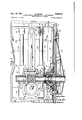
- Fig. 1 is a vertical view of a washing machine incorporating the agitator of my invention, certain of the parts being broken away and shown in section, and certain otherwise hidden parts being indicated by dash lines;
- Fig. 2 is an enlarged fragmentary section of a clutch used in my machine
- Fig. 3 is an enlarged vertical medial section through the agitator showing a fragment of the tube and with certain parts shown in elevation;
- Fig. 4 is a horizontal section taken from a plane indicated by the line 4-4 of Figs. 1 and 3;
- Fig. 5 is a vertical section taken on the line 5-5 of Figs. 1 and 3.
- the agitator includes a shell or housing of generally rectangular formation which is supported in closely spaced relation to the bottom of the tub and which is provided with a mechanism for moving it in a reciproeating manner transversely across the bottom of the tub.
- the shape of the agitator is such that the materials being washed are intermittently pressed against the side of the tub, first on one side and then on the opposite side.
- the reciprocating motion is accompanied by an intermittent rotary motion.
- the complete machine may include an outer casing i0 having a floor engaging portion ll.
- An inner casing i2 may also be provided and serve to store water after extracting it from the clothes if desired, the inner casing being provided with a bottom l3 having a central aperture II from which rises a tube l5.
- the sheave I9 is connected to a shaft 2
- the clutch preferably comprises any suitable mechanism which will drive the shaft 2
- sleeve 24 in its broader aspects may be considered merely as the support for the tub. Obviously, if the tub is not rotated, the sleeve could be omitted. In the embodiment shown, however, the motor frictionally drives the shaft 2
- the sheave 9 is rotatably journalled on the shaft 2
- a suitable clutch lining 21 secured to the ring'25 may provide the desired friction surface.
- the ring 25 is keyed at 28 to the shaft 2
- a cup shaped sleeve 29 which is provided with a toothed upper extremity 30.
- the sleeve 24 extends downward inside of the cup and engages with a thrust bearing 3
- a movable sleeve 32 is provided having a lower toothed end 33 adapted for interlocking engagement with the teeth 30.
- This sleeve is provided with a keyway 34 slidably engaged with a key 35 carried by the sleeve 24.
- An operating yoke 36 is provided, being carried on a rod 31 journalled in brackets 38 carried by the bottom wall or frame of the housing.
- the yoke is provided with arms 39 having pins 40 which engage in the annular channel 4
- a lever 42 is provided on one end of the rod 31 which extends exteriorly of the housing.
- the other end of the rod is provided with a crank arm 43 connected by a spring 44 to the frame and so arranged that the clutch is either held in the engaged or disengaged position as desired. Stops 45 may be provided to determine the limits to which the lever 42 may be moved.
- the drive is from the sheave l9 through the friction material 21 to the ring 25 and thence to the shaft 2
- the lever 42 is moved to the opposite position shown, which moves the toothed sleeve 32 into engagement with the sleeve 29 which then drives the upper sleeve 32 and through the key 35, the sleeve 24.
- a feature of this type of drive isthat slippage between the parts 25, 26 and 21 occurs when the sleeve 24 is picked up, thus preventing stalling of the motor.
- Still another type of mechanism is illustrated and claimed in my copending application, Serial No. 648,117 filed February 16, 1946.
- the upper end of the casings l0 and I2 are provided with a suitable closure, but since it does not form a part of the present invention, no further description is deemed necessary.
- the sleeve 24 is rigidly connected to the bottom of the tub 53, a bracket 54 (Fig. 3) providing additional rigidity for the connection.
- the agitator and its associated drive may move in a rotary direction during the process of reciprocation, and one means for effecting this movement is obtained by the effects of torque on the parts and a slight vertical relative movement between certain of parts, which changes the frictional resistance.
- a, bearin member Secured to the bottom of the tub by bolts 60, inside and surrounding the opening 58 for the shaft 2
- the sleeve is provided with a counter bore which receives the outer race of a bearing 64, the inner race of which is secured on the shaft 2
- a second ring65 Also secured by the bolts 60 on top of the ring 6
- This ring carries the weight of the housing for the agitator drive gears.
- the bottom of the housing' is generally bell shaped, being provided at its lower extremity with a flange 12 to which the ring 10 is secured by studs 13.
- the heads of the stud are countersunk in the bottom surface of the ring, and the shanks are screw threaded into the housing.
- the same studs also hold in place a guard ring 14 which cooperates with the seg ments as described in the aforementioned Patent No.- 2,465,216.
- the guard rin is provided with an annular raised portion 15 to provide clearance space for the heads of the bolts 60 and which is formed with an openin 16 through which access may be had to the bolts 60.
- the sleeve 62 on the member 6
- a slight clearance space is provided between the flange of the friction ring I0 which is disposed in the channel formed by the part 66 of the ring 65 whereby a slight degree of vertical movement of the housing may be realized with respect to the member 6
- is, however, held against upward movement by the bearing 64, the upper edge of which engages with the shoulder 18 in the sleeve 62.
- a seal is provided which prevents washing fluid from obtaining access to the bearing 64 and leaking out around the shaft 2
- the seal comprises a ring 8
- the ring 62 carries a self lubricated plain bearing of oilless composition material 33 disposed in the upper face of the ring 82 and surrounding the shaft 2
- the rings and 82 are provided with telescoping sleeves 85 and 86,
- a helical spring 81 is provided, the lower end of which engages with an inwardly extending flange on the ring 80, and the upper end of which presses against the bearing 83, forcing the bearing 83 into fluid tight engagement with a seat 88 on a ring 89.
- the ring 89 is secured in a bore 90 in the upper end of the housing by a press fit, A gasket 9
- thehousing is formed with an annular chamber 04 in which is disposed a seal 35 which prevents leakage of lubricant from the gear housing proper from around the shaft.
- the gear housing which contains a worm and worm gear. which worm gear drives a crank arm that is connected to the agitator.
- the housing at this point comprises a casing I00, having a generally cylindrical part IOI (Fig. 4) for housing the worm I02 and a circular part I03 for housing the worm gear I04.
- extends through the chamber IOI, being rotatably journalled therein in bushings I and carries the worm I02 which is keyed thereto by a pin I05. It should be noted that, in the position hown, there is a clearance space between the ends of the worm and the bearings I05 which, as will appear later, allows a certain amount of relative longitudinal movement between the shaft and its worm and the housing.
- the worm gear I04 is carried on a horizontally disposed shaft I00 being keyed thereon by a key I03.
- the shaft has one end journalled in a bushing IIO of a boss III of the main housing, and the other end in a bushing II 2 of a boss II3 carried by the coverlate II4 which is secured to the housing by screws II5, a suitable gasket IIS being disposed therebetween.
- the end of the boss H3 is provided with a closed end wall I I1 through which is threaded an adjustable thrust screw H3 adapted to engage a ball IIII disposed in a socket I20 in the end of the shaft, the screw being provided with a lock nut I2I.
- the other end of the shaft I08 extends through the other side of the housing and is provided with a reduced threaded end I22 upon which a crank arm I23 is carried.
- the crank arm is provided with a crank pin I24 upon which a pitman I25 is journalled, a suitable bearing I25, which may be of the water lubricatin type being provided between the pin I24 and the pitman.
- a rotary Seal i provided between the crank arm I23 and the boss III'which prevents washing fluid from obtaining access to the interior of the housing, as well as preventing lubricants from escaping, and preferably comprise a ring shaped bushing I30 of the so-called oilless type which is pressed on a reduced end I3I of the housing, a suitable gasket being provided at I32 between a shoulder on the bushing and the shoulder at the junction of the reduced portion I 3I and III.
- the crank arm, on the side toward the housing is provided with a circular channel I33 which surrounds the shaft I22 in spaced relation thereto to provide a hub I34 on the crank at the shaft, whichhub is provided with a seat I35.
- a resilient washer I31 of rubber or like material has its inner portion seated on said seat being clamped between the seat and a metal washer I30, the metal washer being engaged by the shoulder formed at the junction of the reduced part I22 with the main body I03 of the shaft.
- the crank arm being threaded on the part I22, the washer engages with the washer I31 pressin it against the metal washer I38 which is'held. by the shoulder securely clamping the rubber washer in fluid sealing engagement with the shaft.
- the extremity of the rubber washer I31 is secured in a cup shaped metal ring I40, being held in the ring by a cup shaped oilless bushing I which has a press fit with the circumferential wall of the ring I40.
- the bushings I3I and NI are provided with ground seating surfaces adapted for engagement with each other and permitting the ring I to revolve against the ring I30 and still maintain a fiuidtight seat.
- the ring I" i held spring pressed against the ring I30 by springs I43 which are seated in recesses I44 in the bottom of the channel I33 and engage over projections I45 on the ring.
- this seal may take various forms other than that shown,'the illustration being for the purpose of affording a better understanding of the invention.
- the recesses I44 could be replaced by a single annular channel, and a single helical spring could surround the shaft, one end being sealed in the channel. and the other end being seated against the cup I40.
- the washer I31 being resilient, the two oilless bushings are held in engagement with each other.
- the crank and its associated pitman are adapted, upon rotation of the crank, to reciprocate the agitator transversely across the bottom of the tub.
- the agitator per se is a generally elongated dome shape; being hollowjit fits over the gear housing and its associated parts.
- the gear housing supports a carriage which,
- the housing is provided with pairs of guides disposed in vertically spaced relation.
- the upper guides are shown at I-I5I, and the lower guides at I52 and I53.
- Each pair of guides is provided with horizontally and axially aligned cylindrical bores which support rods I54 and I that reciprocate therein.
- the guides may be made integral with the rest of the housing, it is convenient to form them in two parts.
- the housing is provided with upwardly projecting portions which have semicylindrical portions I50 and I5I and the downwardly projecting parts of similar formation with the semi-cylindrical parts I52 and I 53.
- Caps are provided at I53 having semi-cylindrical parts I5I' and I53 (Fig. 5) and which are clamped to the housing by cap screws I59, to provide the cylindrical guides.
- the guides and rods could take other shapes than that shown.
- the rods could be rectangular bars, angle shaped, or T-shaped, in which event the guides would have a complementary formation.
- Bushings may be provided in the guides if desired.
- the rods I54 and I55 thus extend through the guides in vertical spaced parallel relation, and are reciprocable in the guides.
- the agitator is supported by the rods I54 and I55, being secured to the ends thereof. It may take various forms and be constructed in various manners. It may be made of plastic or metal. In the present instance, for purpose of illustration only, I have shown a fabricated agitator. Generally, it comprises a body of dome shaped formation and substantially rectangular in plan view. It is formed by providing end castings I10 having vertically spaced bored bosses III and I12 that provide sockets at I13 which receive the ends of the rods I54 and I55. The rods are secured therein by screws I14 extending from the outside of the housing inward. The screw heads I14 engage with the bottom wall of the bore I15 and are threaded into the ends of the rods securely and rigidly connecting the ends I10 to the rods.
- Both of the end parts may be substantially the same except that the right end casting as viewed in the figures is provided with a means for connecting it to the pitman I25. As best shown in Fig. 3, the end casting I intermediate the bosses I'll-I12 is provided with a pair of bosses Ill.
- the bosses I'I'I are disposed in horizontally spaced relation and are provided with inwardly facing seating surfaces I18.
- a wrist pin is provided and comprises a cylindrical center part I18 and the longitudinal extensions I80 having seats opposite to I18 and held on-the bosses by cap screws I8I.
- the cap screws are countersunk in the outside of the housing and extend through the bosses being threaded into the parts I80 of the wrist pin.
- the pitman I25 (Fig. 3) is formed as shown, the end opposite the crank I23 being offset and provided with a wrist pin engaging part I82.
- a bushing I83 is provided in which the wrist pin is journalled.
- the two end housings I10 are also connected to each other by angle bars I85, at the lower bottom corners and a third bar I85 at the top.
- the housings are also provided with a plurality of inwardly extending bosses or lugs I88 which extend from the ends toward the other housing and provide an edge support for a sheet metal member I90 which bridges the space between the two spaced end housings.
- Clips I9I may be provided at the lower edges of the member I90 for engagement with the bars I85 to hold the same in position.
- the edges of the member I90' mayalso be secured to the lugs I88 by rivets I92.
- the agitator may also be provided with one or more fins I95 on opposite ends if desired.
- the rods I54 which support the agitator, need not be circular in form but can be angle bars or of any desired form. In event the cross sectional form of the rods is different than that shown, the guides I50 to I53 inclusive, would also be shaped to conform thereto.
- the agitator at the extremity of its movement in either direction comes in relatively close spaced relation to the tub wall, it being moved from the one extremity shown to the otherextremity which would be an equal distance to the left as viewed in that figure.
- This transverse movement of the agitator acquires its greatest velocity when the agitator is midway in its movement and its lowest velocity when it reaches the end of its movement.
- the end result is that the clothes are intermittently pressed against opposite sides of the tub.
- the mass of the agitator is such that the movement of the fluid is rather violent, causing a considerable turbulence and moving the clothes and the water through each other. It should be particularly noted that the reversal of movement occurs at the minimum of speed, and that the clothes are not suddenly jerked upon the reversal of movement with the resultant tendency to tear them.
- the transverse movement of the agitator is also accompanied by an intermittent but gradual rotary movement. This movement is such that if the agitator meets with a predetermined amount of resistance, it ceases to turn until the clothes'are so distributed that the resistance is removed. This rotary movement thus also serves to distribute the clothes about the'container in such a manner that all the articles are washed an equal amount.
- the rotary movement is effected by the action of the reciprocating drive as follows: 1
- the construction is such that the agitator, its support, and the associated housing is free to rotate about the axis of the shaft 2I.
- the worm gear will be driven in a clockwise direction.
- the resultant forces due to the driving rotation between the worm and worm gear is such the worm has a tendency to be raised and the worm gear to be pushed downward.
- This force varies, depending upon the resistance to the drive, which is directly dependant upon the effort required to push the agitator toward the side of the tub, since the shaft 2I to which the worm is attached is held against vertical upward movement by the thrust bearing 84.
- the only movement of which the shaft partakes is a rotary to the housing pressing the same downward.
- the agitator may and does rotate a certain amount. This rotation is not a steady rotation but an intermittent rotation. Furthermore, the amount of rotation will vary, depending upon the amount of resistance that the agitator meets by its rotary engagement with the clothes; that is, if the clothes are unevenly distributed and there should be' a space where there are no clothes, the agitator would move quickly through this space until it hits against the clothes, at which time it would stop.
- the movement of the agitator is an intermittent one of but a few degrees for each stroke.
- the normal operation is for the agitator to reciprocate rapidly in a transverse direction diametrically across the tub while partaking of an intermittent rotary movement of a few degrees for each stroke, which movements causes the clothes to be washed and maintains an even distribution thereof during the washing.
- the tub is spun to extract the water therefrom.
- this invention in its broader aspects contemplates the use of this agitator and its drive with any ordinary type of washing machine, including those using the roll type wringer or the separate spinner for extracting the water from the clothes.
- the only limitation as to the type of tub being that for best results and a more even distribution of the clothes, the tub should preferably be round.
- the operating handle is moved to its alternate position wherein the clutch elements 32 and 29 engage.
- the agitator 700 R. P. M. to be quite satisfactory.
- the out of balance weight is relatively small. Such out of balance is taken care of by a suitable suspension not shown, and of which there are many known in the art.
- the water centrifuged from the clothes escapes up the inclined wall of the tub from around the upper edge thereof.
- a metal ring 200 secured to the upper end of the tub assists in maintaining the proper balance thereof. After the water is extracted from the tub, the motor is tie-energized and the clothes may be removed.
- a washing machine comprising a tub, an agitator for said tub adapted to push the clothes against the side of the tub, mounting means for said agitator supporting the agitator for reciprocation transversely of the tub, drive means for rotating the tub comprising a tube connected to the tub and a rotary shaft inside of the tube for driving said agitator, clutch means for driving the shaft and operable to drive said sleeve with the shaft to rotate the tub.
- a washing machine comprising a tub mounted for revolution about its axis, an agitator for said tub disposed for reciprocation transversely to the axis thereof, a transmission for operating said'agitator disposed inside of said agitator, said transmission and said agitator being mounted for rotation about, an axis, and means connecting said tub and transmission and operable by the loading of the agitator to cause rotation of the agitator.
- a washing machine of the class described including a tub mounted for rotation about its vertical axis, a transmission disposed inside the tub, guide means on said transmission, an agitator journalled in said guide means, said transmission including a worm and a worm gear, a shaft for driving the worm and a crank driven by the wo m ear and pitman means connecting the crank to the agitator, said agitator being movable in said guide means transversely of the tub to press thematerials being washed against the sides of the tub.
- a washing machine including a tub, an agitator for said tub comprising a substantially rectangular hollow member, a mounting for said agitator comprising a transmission housing extending inside the agitator and having guides, guide rods connected to said agitator and disposed in said guides for guiding said agitator in its movement transversely across the tub, a crank connected to said agitator by a pitman and a worm gear and worm for rotating said crank disposed in said housing, a shaft for driving said worm gear extending through the bottom of the tub, said transmission being free to rotate on the bottom of the tub, and having frictional engagement with the bottom of the tub, said shaft being journalled in bearings and held thereby against 1 vertical movement, said housing being supported for vertical movement relative to said shaft and operable upon a predetermined resistance to movement of said crank to be raised from frictional engagement with the tub, said agitator being rotated upon the release of said friction.
- a washing machine including a tub, a transmission disposed inside the tub, guide means transmission disposed inside the tub, guide means on said transmission formed with guide ways extending transversely of said tub, an agitator, rod means extending longitudinally of the agitator and journalled in said guide ways, said transmission including a worm and a worm gear, a shaft for driving the worm and a crank driven by the worm gear, pitman means connecting the crank to the agitator, said agitator being movable in said guide means transversely of the tub to press the materials being washed against the sides of the tub.
- a washing machine including a tub, a transmission housing disposed inside the tub, guide means on said housing formed with guide ways extending transversely of said tub, an agitator, rod means extending longitudinally of the agitator and reciprocably journalled in said guide ways, said housing enclosing a gear drive, a drive shaft connected to said gear drive and a crank driven by the gear drive, connecting means connecting the crank to the agitator, said agitator being movable in said guide means: transversely of the tub to press the materials being washed against the sides of the tub.
- a washing machine including a tub, an agitator disposed inside said tub, a housing support member carried by said tub and a housing rotatably Journalled thereon, said housing being formed with guides, and guide means on said a81- tator reciprocably Journalled in said guides, a rotary shaft extending through said support into said housing and gear means driven thereby, and means connecting said gear means to said agitator for moving said agitator'on said guides, said housing having portions for frictional engagement with said support and arranged to be moved from frictional engagement upon a decrease in load against said agitator to permit the driving force on the gear means to revolve the housing and the agitator.
- a washing machine including a tub, a hollow agitatordisposed inside said tub, a'housing support member carried by said tub and a housing rotatably journalled thereon, means on said housing support to hold said housing for limited upward movement on the support, said housing being formed with guides, and guide rods extending between the walls of said agitator and reciprocably journalled in said guides, a rotary shaft extending through said support into said housing and a worm carried by said shaft and a worm gear driven thereby, and crank means connecting to said worm gear and connected to said agitator for moving said agitator on said guides, said housing having portions for'frictional engagement with said support, said worm and worm gear adapted to determine said frictional engagement, said housing adapted to rotate upon a decrease in load against said agitator to permit the driving force on the gear means to revolve the housing and the agitator.
- a washing machine comprising a tub, an agitator disposed in said tub, a shaft extending through the wall of said tub, a transmission housing within the tub, said shaft extending into and supporting saidhousing, transmission means within said housing driven by said shaft andoperably connected to said agitator, said housing normally being free to revolve about said shaft and free within limits to move longitudinally of said shaft, friction clutch means disposed on said housing and said tub about said shaft and engageable to prevent rotation of said housing, said clutch means being operable by movement of said housing longitudinally of said shaft to hold said housing fromrevol'ving when force is applied on said housing.
- a washing machine comprising a tub, an agitator disposed in said tub, a shaft extending through a wall of said tub, a transmission housing within the tub, said shaft extending into said housing, transmission gear means within said housing driven by said shaft and operably con- ,nected to said agitator, said housing and agitator normally being free to revolve about said shaft and being free within limits to move longitudinally of said shaft, friction means on said housing adjacent the shaft, means on said tub adapted to be engaged with said first named friction means upon longitudinal movement of said housing to prevent rotative movement thereof,
- said housing being adapted to be moved longitudinally of said shaft in response to horizonal forces on said agitator.
- An apparatus of the class described comprising: a container, an. agitator in said container, support means supporting said agitator for straight-line reciprocatory motion transversely across said container, said agitator being adapted to press the material being agitated toward the walls of said container, clutch means engageable between said container and said support means to hold said support means against rotative force, said clutch means being arranged to be moved into holding engagement by the force of the pressing of said material by said agitator and to be released upon decrease of said force below a predetermined value, and drive means connected to said agitator adapted to reciprocate said agitator and also to rotate said agitator and support means together when said clutch is released.
Description
4 Sheets-Sheet 1 Sept. 18, 1951 G. FIELDS CLOTHES WASHING MACHINE WITH A HORIZONTALLY RECIPROCATING AGITATOR Filed Oct. 4, 1945 Sept. 18, 1951 G. FIELDS CLOTHES WASHING MACHINE WITH A HORIZONTALLY RECIPROCATING AGITATOR 4 Sheets-Sheet 2 Filed Oct. 4, 1945 MOB/V5 Y Sept. 18, 1951 c; FIELDS CLOTHES WASHING MKCHINE WITH A HORIZONTALLY RECIPROCATING AGITATOR Filed Oct. 4, 1945 4 Sheets-Sheet 5 JTTOP/VEY' Sept. 18, 1951 RECIPROCATING Filed Oct. 4, 1945 G. FIELDS CLOTHES WASHING MACHINE WITH A HORIZONTALLY AGITATOR 4 Sheets-Sheet 4 i l 2 i y E V E I r 6 JNVENTOR.
Geo rye fif /ais- A TTOR/VE Y Patented Sept. 18, 1951 CLOTHES-WASHING MACHINE WITH A HORIZONTALLY RECIPROCATING AGI- TATOR George Fields, Wilmette, Ill., assignor to Admiral Corporation, Chicago, 111., a corporation of Delaware Application October 4, 1945, Serial No. 620,209
11 Claims. (Cl. 68-23) This invention relates to improvements in a washing machine, and more particularly to an improved means for agitating the clothes in the washing fluid to effect the washing thereof.
Heretofore the clothes have been agitated in the washing fluid in several different manners, the most popular of which comprises placing an agitator inside the tub which may partake of an oscillating movement therein or by placin the clothes in a rotating drum inside the tub and which carries the clothes through the washing fluid. The present invention has to do particularly with the type of agitator which moves inside the tub.
One of the principal defects in previous agitator devices was that the agitator oscillated with considerable speed and had a tendency to catch and tear the clothes. This is particularly true of that type of agitator whichlis provided with vanes and utilizes an oscillating movement. The sudden changes in direction of the agitator often causes the vanes to catch in the clothing, which is torn thereby. If the agitator is designed so that it does not catch the clothing, then it loses some of its eiilciency as an agitator which detracts from its ability to properly clean the clothes and thus makes it necessary to increase the washing time. Still another disadvantage of the prior devices resided in the necessity for a complicated gearing system for effecting the desired reciprocating motion. Among the other disadvantages was the perfecting of suitable seals to retain the washing fluied against leakage from around the agitator as well as preventing the leakage of the, lubricant from the gear housing.
By my present invention, I have provided a mechanism whereby the materials to be washed are moved through the washing fluid in a highly efficient manner but wherein the tendency to tear the material is completely eliminated. Furthermore, the mechanism for effecting the desired movement has been greatly simplified, which not only reduces the amount of servicing but decreases the weight of the machine as well as the cost of manufacture. Furthermore, by the present invention, the clothes are more evenly distributed and washed.
Although the invention about to be described will be describedin connection with a type of washing machine where the materials are first washed and then centrifuged to remove the ex cess water," it will be apparent that the mechanism is equally useful in conjunction with washing machines of the 'so-called wringer or separate spinner type, and that therefore the invention is not limited in its scope to the particular type of machine disclosed or otherwise than as is set forth the in the appended claims.
Generally speaking, the apparatus includes an agitator which moves diametrically to and fro across the axis of the tub and at the same time partakes of a gradual rotary movement in the tub. Preferably, the reciprocatory movement is positive and the rotary movement depends on the loading of the mechanism.
The manner of operation and the construction of the apparatus, as well as other advantages due to the construction, will become more apparent from the following description of an embodiment thereof, the description being illustrated by the accompanying drawings and forming a part of this specification.
In the drawings:
Fig. 1 is a vertical view of a washing machine incorporating the agitator of my invention, certain of the parts being broken away and shown in section, and certain otherwise hidden parts being indicated by dash lines;
Fig. 2 is an enlarged fragmentary section of a clutch used in my machine;
Fig. 3 is an enlarged vertical medial section through the agitator showing a fragment of the tube and with certain parts shown in elevation;
Fig. 4 is a horizontal section taken from a plane indicated by the line 4-4 of Figs. 1 and 3; and
Fig. 5 is a vertical section taken on the line 5-5 of Figs. 1 and 3.
Preferably, the agitator includes a shell or housing of generally rectangular formation which is supported in closely spaced relation to the bottom of the tub and which is provided with a mechanism for moving it in a reciproeating manner transversely across the bottom of the tub. The shape of the agitator is such that the materials being washed are intermittently pressed against the side of the tub, first on one side and then on the opposite side.
The reciprocating motion is accompanied by an intermittent rotary motion.
Referring now to the drawings, throughout which like parts are designated by like reference characters, and more particularly to Fig. l, the complete machine may include an outer casing i0 having a floor engaging portion ll. An inner casing i2 may also be provided and serve to store water after extracting it from the clothes if desired, the inner casing being provided with a bottom l3 having a central aperture II from which rises a tube l5. Supported below the bottom l3, on a frame [6, is a motor that is provided with a sheave I8 which drives a second sheave l9 through a belt 20. The sheave I9 is connected to a shaft 2| through a suitable clutch mechanism.
The clutch preferably comprises any suitable mechanism which will drive the shaft 2| with a continuous rotary motion and which when -desired will also drive a sleeve 24 with a continuous rotary motion. Since the invention is adaptable to machines where the tub is not rotated, the
In the embodiment'shown, the sheave 9 is rotatably journalled on the shaft 2| and drives the shaft through frictional engagement with a friction ring 25 which engages with a friction surface 26 on the sheave IS. A suitable clutch lining 21 secured to the ring'25 may provide the desired friction surface. The ring 25 is keyed at 28 to the shaft 2|. Also secured to the shaft 2| is a cup shaped sleeve 29 which is provided with a toothed upper extremity 30. The sleeve 24 extends downward inside of the cup and engages with a thrust bearing 3|. A movable sleeve 32 is provided having a lower toothed end 33 adapted for interlocking engagement with the teeth 30. This sleeve is provided with a keyway 34 slidably engaged with a key 35 carried by the sleeve 24. An operating yoke 36 is provided, being carried on a rod 31 journalled in brackets 38 carried by the bottom wall or frame of the housing. The yoke is provided with arms 39 having pins 40 which engage in the annular channel 4| of the sleeve. A lever 42 is provided on one end of the rod 31 which extends exteriorly of the housing. The other end of the rod is provided with a crank arm 43 connected by a spring 44 to the frame and so arranged that the clutch is either held in the engaged or disengaged position as desired. Stops 45 may be provided to determine the limits to which the lever 42 may be moved.
The drive is from the sheave l9 through the friction material 21 to the ring 25 and thence to the shaft 2|. When it is desired to rotate the sleeve, the lever 42 is moved to the opposite position shown, which moves the toothed sleeve 32 into engagement with the sleeve 29 which then drives the upper sleeve 32 and through the key 35, the sleeve 24. A feature of this type of drive isthat slippage between the parts 25, 26 and 21 occurs when the sleeve 24 is picked up, thus preventing stalling of the motor. I also contemplate the use of a fluid drive coupling in place of the parts 25, 26 and 21, which effects substantially the same operation. Still another type of mechanism is illustrated and claimed in my copending application, Serial No. 648,117 filed February 16, 1946.
The upper end of the casings l0 and I2 are provided with a suitable closure, but since it does not form a part of the present invention, no further description is deemed necessary.
The sleeve 24 is rigidly connected to the bottom of the tub 53, a bracket 54 (Fig. 3) providing additional rigidity for the connection. The
' bolts 53 connect the tub and the periphery of the bracket together as well as the lock ring 56 which engages the lower edges of the removable segments 51 which are the subject of my copending application, Serial No. 600,802, filed June 21, 1945, now U. S. Patent No. 2,465,216.
The agitator and its associated drive may move in a rotary direction during the process of reciprocation, and one means for effecting this movement is obtained by the effects of torque on the parts and a slight vertical relative movement between certain of parts, which changes the frictional resistance.
Secured to the bottom of the tub by bolts 60, inside and surrounding the opening 58 for the shaft 2|, is a, bearin member which comprises a ring shaped bottom portion 6| provided with a coaxial sleeve 62 which extends upward around the shaft'2l and is spaced therefrom. The sleeve is provided with a counter bore which receives the outer race of a bearing 64, the inner race of which is secured on the shaft 2|. abutting a shoulder on the shaft. Also secured by the bolts 60 on top of the ring 6| is a second ring65 having an overhanging part 66 which, together with the ring 6|, provides an annular channel.
Seated on the rin 6| and held in place by the ring 65-66 i a friction ring 10. This ring carries the weight of the housing for the agitator drive gears. The bottom of the housing'is generally bell shaped, being provided at its lower extremity with a flange 12 to which the ring 10 is secured by studs 13. The heads of the stud are countersunk in the bottom surface of the ring, and the shanks are screw threaded into the housing. The same studs also hold in place a guard ring 14 which cooperates with the seg ments as described in the aforementioned Patent No.- 2,465,216. The guard rin is provided with an annular raised portion 15 to provide clearance space for the heads of the bolts 60 and which is formed with an openin 16 through which access may be had to the bolts 60.
The sleeve 62, on the member 6|, extends up into a bore 11 of the gear housing, preferably this is aclose sliding fit. A slight clearance space is provided between the flange of the friction ring I0 which is disposed in the channel formed by the part 66 of the ring 65 whereby a slight degree of vertical movement of the housing may be realized with respect to the member 6| and its associated sleeve 62. The shaft 2| is, however, held against upward movement by the bearing 64, the upper edge of which engages with the shoulder 18 in the sleeve 62.
A seal is provided which prevents washing fluid from obtaining access to the bearing 64 and leaking out around the shaft 2|, and permits the relative vertical movement. The seal comprises a ring 8|! having a press fit with the interior of the sleeve 62 at the boss 18 and is connected by a flexible sleeve 8| to an upper ring 82. The ring 62 carries a self lubricated plain bearing of oilless composition material 33 disposed in the upper face of the ring 82 and surrounding the shaft 2| with a, close fit. The rings and 82 are provided with telescoping sleeves 85 and 86,
and a helical spring 81 is provided, the lower end of which engages with an inwardly extending flange on the ring 80, and the upper end of which presses against the bearing 83, forcing the bearing 83 into fluid tight engagement with a seat 88 on a ring 89. The ring 89 is secured in a bore 90 in the upper end of the housing by a press fit, A gasket 9| may also be provided to further assure thatthe ring 03 is sealed against the leakage of fluid past it.
Above the ring 80, thehousing is formed with an annular chamber 04 in which is disposed a seal 35 which prevents leakage of lubricant from the gear housing proper from around the shaft.
Above the bell shaped bottom portion of the housing just described, is disposed the gear housing which contains a worm and worm gear. which worm gear drives a crank arm that is connected to the agitator. The housing at this point comprises a casing I00, having a generally cylindrical part IOI (Fig. 4) for housing the worm I02 and a circular part I03 for housing the worm gear I04. The shaft 2| extends through the chamber IOI, being rotatably journalled therein in bushings I and carries the worm I02 which is keyed thereto by a pin I05. It should be noted that, in the position hown, there is a clearance space between the ends of the worm and the bearings I05 which, as will appear later, allows a certain amount of relative longitudinal movement between the shaft and its worm and the housing.
The worm gear I04 is carried on a horizontally disposed shaft I00 being keyed thereon by a key I03. The shaft has one end journalled in a bushing IIO of a boss III of the main housing, and the other end in a bushing II 2 of a boss II3 carried by the coverlate II4 which is secured to the housing by screws II5, a suitable gasket IIS being disposed therebetween. The end of the boss H3 is provided with a closed end wall I I1 through which is threaded an adjustable thrust screw H3 adapted to engage a ball IIII disposed in a socket I20 in the end of the shaft, the screw being provided with a lock nut I2I. I
The other end of the shaft I08 extends through the other side of the housing and is provided with a reduced threaded end I22 upon which a crank arm I23 is carried. The crank arm is provided with a crank pin I24 upon which a pitman I25 is journalled, a suitable bearing I25, which may be of the water lubricatin type being provided between the pin I24 and the pitman.
A rotary Seal i provided between the crank arm I23 and the boss III'which prevents washing fluid from obtaining access to the interior of the housing, as well as preventing lubricants from escaping, and preferably comprise a ring shaped bushing I30 of the so-called oilless type which is pressed on a reduced end I3I of the housing, a suitable gasket being provided at I32 between a shoulder on the bushing and the shoulder at the junction of the reduced portion I 3I and III. The crank arm, on the side toward the housing is provided with a circular channel I33 which surrounds the shaft I22 in spaced relation thereto to provide a hub I34 on the crank at the shaft, whichhub is provided with a seat I35. A resilient washer I31 of rubber or like material has its inner portion seated on said seat being clamped between the seat and a metal washer I30, the metal washer being engaged by the shoulder formed at the junction of the reduced part I22 with the main body I03 of the shaft. The crank arm being threaded on the part I22, the washer engages with the washer I31 pressin it against the metal washer I38 which is'held. by the shoulder securely clamping the rubber washer in fluid sealing engagement with the shaft.
The extremity of the rubber washer I31 is secured in a cup shaped metal ring I40, being held in the ring by a cup shaped oilless bushing I which has a press fit with the circumferential wall of the ring I40. The bushings I3I and NI are provided with ground seating surfaces adapted for engagement with each other and permitting the ring I to revolve against the ring I30 and still maintain a fiuidtight seat. The ring I" i held spring pressed against the ring I30 by springs I43 which are seated in recesses I44 in the bottom of the channel I33 and engage over projections I45 on the ring.
It should be understood that this seal may take various forms other than that shown,'the illustration being for the purpose of affording a better understanding of the invention. For instance, one modification which will be apparent is that the recesses I44 could be replaced by a single annular channel, and a single helical spring could surround the shaft, one end being sealed in the channel. and the other end being seated against the cup I40. In either event, the washer I31, being resilient, the two oilless bushings are held in engagement with each other.
The crank and its associated pitman are adapted, upon rotation of the crank, to reciprocate the agitator transversely across the bottom of the tub. The agitator per se is a generally elongated dome shape; being hollowjit fits over the gear housing and its associated parts.
The gear housing supports a carriage which,
in turn, supports the agitator. With this in view,
the housing is provided with pairs of guides disposed in vertically spaced relation. The upper guides are shown at I-I5I, and the lower guides at I52 and I53. Each pair of guides is provided with horizontally and axially aligned cylindrical bores which support rods I54 and I that reciprocate therein. Although the guides may be made integral with the rest of the housing, it is convenient to form them in two parts.
In this instance, the housing is provided with upwardly projecting portions which have semicylindrical portions I50 and I5I and the downwardly projecting parts of similar formation with the semi-cylindrical parts I52 and I 53. Caps are provided at I53 having semi-cylindrical parts I5I' and I53 (Fig. 5) and which are clamped to the housing by cap screws I59, to provide the cylindrical guides. Obviously, the guides and rods could take other shapes than that shown. For instance, the rods could be rectangular bars, angle shaped, or T-shaped, in which event the guides would have a complementary formation. Bushings may be provided in the guides if desired. The rods I54 and I55 thus extend through the guides in vertical spaced parallel relation, and are reciprocable in the guides.
The agitator is supported by the rods I54 and I55, being secured to the ends thereof. It may take various forms and be constructed in various manners. It may be made of plastic or metal. In the present instance, for purpose of illustration only, I have shown a fabricated agitator. Generally, it comprises a body of dome shaped formation and substantially rectangular in plan view. It is formed by providing end castings I10 having vertically spaced bored bosses III and I12 that provide sockets at I13 which receive the ends of the rods I54 and I55. The rods are secured therein by screws I14 extending from the outside of the housing inward. The screw heads I14 engage with the bottom wall of the bore I15 and are threaded into the ends of the rods securely and rigidly connecting the ends I10 to the rods.
Both of the end parts may be substantially the same except that the right end casting as viewed in the figures is provided with a means for connecting it to the pitman I25. As best shown in Fig. 3, the end casting I intermediate the bosses I'll-I12 is provided with a pair of bosses Ill.
The bosses I'I'I are disposed in horizontally spaced relation and are provided with inwardly facing seating surfaces I18. A wrist pin is provided and comprises a cylindrical center part I18 and the longitudinal extensions I80 having seats opposite to I18 and held on-the bosses by cap screws I8I. The cap screws are countersunk in the outside of the housing and extend through the bosses being threaded into the parts I80 of the wrist pin.
The pitman I25 (Fig. 3) is formed as shown, the end opposite the crank I23 being offset and provided with a wrist pin engaging part I82. A bushing I83 is provided in which the wrist pin is journalled.
The two end housings I10 are also connected to each other by angle bars I85, at the lower bottom corners and a third bar I85 at the top. The housings are also provided with a plurality of inwardly extending bosses or lugs I88 which extend from the ends toward the other housing and provide an edge support for a sheet metal member I90 which bridges the space between the two spaced end housings. Clips I9I may be provided at the lower edges of the member I90 for engagement with the bars I85 to hold the same in position. The edges of the member I90'mayalso be secured to the lugs I88 by rivets I92.
The agitator may also be provided with one or more fins I95 on opposite ends if desired. The rods I54, which support the agitator, need not be circular in form but can be angle bars or of any desired form. In event the cross sectional form of the rods is different than that shown, the guides I50 to I53 inclusive, would also be shaped to conform thereto.
In operation, it being assumed that the tub is filled to a predetermined level with a washing fluid, such as water, with the proper detergents added, and that the materials such as clothes to be washed are immersed in the water. With the lever 42, in the position shown, the motor is energized, rotating the pulley I9 which by frictional engagement through the facing 2! drives the ring 25 and hence the shaft 2I. This shaft 2I rotates the worm I02 and it in turn drives the worm gear I04 which rotates the crank arm I 23.
As shown in Fig. 1, the agitator at the extremity of its movement in either direction comes in relatively close spaced relation to the tub wall, it being moved from the one extremity shown to the otherextremity which would be an equal distance to the left as viewed in that figure.
This transverse movement of the agitator acquires its greatest velocity when the agitator is midway in its movement and its lowest velocity when it reaches the end of its movement. The end result is that the clothes are intermittently pressed against opposite sides of the tub. The mass of the agitator is such that the movement of the fluid is rather violent, causing a considerable turbulence and moving the clothes and the water through each other. It should be particularly noted that the reversal of movement occurs at the minimum of speed, and that the clothes are not suddenly jerked upon the reversal of movement with the resultant tendency to tear them.
8 The transverse movement of the agitator is also accompanied by an intermittent but gradual rotary movement. This movement is such that if the agitator meets with a predetermined amount of resistance, it ceases to turn until the clothes'are so distributed that the resistance is removed. This rotary movement thus also serves to distribute the clothes about the'container in such a manner that all the articles are washed an equal amount. I The rotary movement is effected by the action of the reciprocating drive as follows: 1
It will be seen that the construction is such that the agitator, its support, and the associated housing is free to rotate about the axis of the shaft 2I.
If the shaft 2I is rotated in a counterclockwise direction, the worm gear will be driven in a clockwise direction. The resultant forces due to the driving rotation between the worm and worm gear is such the worm has a tendency to be raised and the worm gear to be pushed downward. This force varies, depending upon the resistance to the drive, which is directly dependant upon the effort required to push the agitator toward the side of the tub, since the shaft 2I to which the worm is attached is held against vertical upward movement by the thrust bearing 84. The only movement of which the shaft partakes is a rotary to the housing pressing the same downward.
This downward pressure is exerted through the bell shaped bottom or flange 12 through the friction member 10 to the member 5| seated on the bottom of the tub. Therefore, the greater the resistance met by the agitator, the greater the force of the worm gear and worm in opposite directions, and hence the greater the friction exerted between the housing and its support; and it is this friction that normally prevents the rotation of the agitator and its supporting housing. This friction is normally suflicient when the machine is loaded to overcome the normal tendency of the apparatus to rotate because of the rotating shaft 2I. It will be remembered, however, that the clothe are intermittently pressed by the agitator against the wall of the tub and that this pressure is greatest when the agitator is at the limit of its outward movement. When the agitator moves backward toward the center, this pressure is relieved. As a matter of fact, at the start of the movement, the clothes actually help to move the agitator, and, therefore, after the crank moves past dead center, the resistance at that time is the least during the cycle, with the result that the friction which holds the agitator against rotation is least. This friction continues to be relatively light until the agitator again starts to meet resistance when it presses the clothe against the opposite side.
Therefore, during this period, the agitator may and does rotate a certain amount. This rotation is not a steady rotation but an intermittent rotation. Furthermore, the amount of rotation will vary, depending upon the amount of resistance that the agitator meets by its rotary engagement with the clothes; that is, if the clothes are unevenly distributed and there should be' a space where there are no clothes, the agitator would move quickly through this space until it hits against the clothes, at which time it would stop.
This is a very important advantage, because as previously noted. the agitator presses the clothes against the side of the tub. This movement is accompanied also by a displacement of the water, and this carries with it the clothes which are thus immediately distributed in event that they should at any time accumulate in one spot.
In actual practice-when the clothes are evenly distributed, the movement of the agitator is an intermittent one of but a few degrees for each stroke. The normal operation, therefore, is for the agitator to reciprocate rapidly in a transverse direction diametrically across the tub while partaking of an intermittent rotary movement of a few degrees for each stroke, which movements causes the clothes to be washed and maintains an even distribution thereof during the washing.
In this particular embodiment shown, after the clothes are washed, the tub is spun to extract the water therefrom. As previously stated, however, this invention in its broader aspects contemplates the use of this agitator and its drive with any ordinary type of washing machine, including those using the roll type wringer or the separate spinner for extracting the water from the clothes. The only limitation as to the type of tub being that for best results and a more even distribution of the clothes, the tub should preferably be round.
In event, however, that the tub is also used as the extractor, as indicated herein, the operating handle is moved to its alternate position wherein the clutch elements 32 and 29 engage. At this time, since the tub is standing still, the agitator 700 R. P. M. to be quite satisfactory.
Since the major part of the weight of the transmission is centrally disposed, and because the action of the agitator is such as to evenly distribute the clothes, the out of balance weight is relatively small. Such out of balance is taken care of by a suitable suspension not shown, and of which there are many known in the art. The water centrifuged from the clothes escapes up the inclined wall of the tub from around the upper edge thereof. A metal ring 200 secured to the upper end of the tub assists in maintaining the proper balance thereof. After the water is extracted from the tub, the motor is tie-energized and the clothes may be removed.
Other means than that shown may be used to cause the agitator to take the reciprocation movement, the embodiments shown are for the purpose of clarity in disclosing the invention and are not intended as a limitation other than as is set forth in the appended claims. I am aware that numerous and extensive departures may be made therefrom without departing from the spirit or scope of the invention.
I claim:
1. A washing machine comprising a tub, an agitator for said tub adapted to push the clothes against the side of the tub, mounting means for said agitator supporting the agitator for reciprocation transversely of the tub, drive means for rotating the tub comprising a tube connected to the tub and a rotary shaft inside of the tube for driving said agitator, clutch means for driving the shaft and operable to drive said sleeve with the shaft to rotate the tub.
2. A washing machine comprising a tub mounted for revolution about its axis, an agitator for said tub disposed for reciprocation transversely to the axis thereof, a transmission for operating said'agitator disposed inside of said agitator, said transmission and said agitator being mounted for rotation about, an axis, and means connecting said tub and transmission and operable by the loading of the agitator to cause rotation of the agitator. I
3. A washing machine of the class described including a tub mounted for rotation about its vertical axis, a transmission disposed inside the tub, guide means on said transmission, an agitator journalled in said guide means, said transmission including a worm and a worm gear, a shaft for driving the worm and a crank driven by the wo m ear and pitman means connecting the crank to the agitator, said agitator being movable in said guide means transversely of the tub to press thematerials being washed against the sides of the tub.
4. A washing machine including a tub, an agitator for said tub comprising a substantially rectangular hollow member, a mounting for said agitator comprising a transmission housing extending inside the agitator and having guides, guide rods connected to said agitator and disposed in said guides for guiding said agitator in its movement transversely across the tub, a crank connected to said agitator by a pitman and a worm gear and worm for rotating said crank disposed in said housing, a shaft for driving said worm gear extending through the bottom of the tub, said transmission being free to rotate on the bottom of the tub, and having frictional engagement with the bottom of the tub, said shaft being journalled in bearings and held thereby against 1 vertical movement, said housing being supported for vertical movement relative to said shaft and operable upon a predetermined resistance to movement of said crank to be raised from frictional engagement with the tub, said agitator being rotated upon the release of said friction.
5. A washing machine including a tub, a transmission disposed inside the tub, guide means transmission disposed inside the tub, guide means on said transmission formed with guide ways extending transversely of said tub, an agitator, rod means extending longitudinally of the agitator and journalled in said guide ways, said transmission including a worm and a worm gear, a shaft for driving the worm and a crank driven by the worm gear, pitman means connecting the crank to the agitator, said agitator being movable in said guide means transversely of the tub to press the materials being washed against the sides of the tub.
6. A washing machine including a tub, a transmission housing disposed inside the tub, guide means on said housing formed with guide ways extending transversely of said tub, an agitator, rod means extending longitudinally of the agitator and reciprocably journalled in said guide ways, said housing enclosing a gear drive, a drive shaft connected to said gear drive and a crank driven by the gear drive, connecting means connecting the crank to the agitator, said agitator being movable in said guide means: transversely of the tub to press the materials being washed against the sides of the tub.
'7. A washing machine including a tub, an agitator disposed inside said tub, a housing support member carried by said tub and a housing rotatably Journalled thereon, said housing being formed with guides, and guide means on said a81- tator reciprocably Journalled in said guides, a rotary shaft extending through said support into said housing and gear means driven thereby, and means connecting said gear means to said agitator for moving said agitator'on said guides, said housing having portions for frictional engagement with said support and arranged to be moved from frictional engagement upon a decrease in load against said agitator to permit the driving force on the gear means to revolve the housing and the agitator.
8. A washing machine including a tub, a hollow agitatordisposed inside said tub, a'housing support member carried by said tub and a housing rotatably journalled thereon, means on said housing support to hold said housing for limited upward movement on the support, said housing being formed with guides, and guide rods extending between the walls of said agitator and reciprocably journalled in said guides, a rotary shaft extending through said support into said housing and a worm carried by said shaft and a worm gear driven thereby, and crank means connecting to said worm gear and connected to said agitator for moving said agitator on said guides, said housing having portions for'frictional engagement with said support, said worm and worm gear adapted to determine said frictional engagement, said housing adapted to rotate upon a decrease in load against said agitator to permit the driving force on the gear means to revolve the housing and the agitator.
9. A washing machine comprising a tub, an agitator disposed in said tub, a shaft extending through the wall of said tub, a transmission housing within the tub, said shaft extending into and supporting saidhousing, transmission means within said housing driven by said shaft andoperably connected to said agitator, said housing normally being free to revolve about said shaft and free within limits to move longitudinally of said shaft, friction clutch means disposed on said housing and said tub about said shaft and engageable to prevent rotation of said housing, said clutch means being operable by movement of said housing longitudinally of said shaft to hold said housing fromrevol'ving when force is applied on said housing.
10. A washing machine comprising a tub, an agitator disposed in said tub, a shaft extending through a wall of said tub, a transmission housing within the tub, said shaft extending into said housing, transmission gear means within said housing driven by said shaft and operably con- ,nected to said agitator, said housing and agitator normally being free to revolve about said shaft and being free within limits to move longitudinally of said shaft, friction means on said housing adjacent the shaft, means on said tub adapted to be engaged with said first named friction means upon longitudinal movement of said housing to prevent rotative movement thereof,
said housing being adapted to be moved longitudinally of said shaft in response to horizonal forces on said agitator.
11. An apparatus of the class described comprising: a container, an. agitator in said container, support means supporting said agitator for straight-line reciprocatory motion transversely across said container, said agitator being adapted to press the material being agitated toward the walls of said container, clutch means engageable between said container and said support means to hold said support means against rotative force, said clutch means being arranged to be moved into holding engagement by the force of the pressing of said material by said agitator and to be released upon decrease of said force below a predetermined value, and drive means connected to said agitator adapted to reciprocate said agitator and also to rotate said agitator and support means together when said clutch is released.
GEORGE FIELDS.
REFERENCES CITED UNITED STATES PATENTS Number Name Date Re. 18,010 Schuyler Mar. 24, 1931 988,214 Sherwood May 28, 1911 1,718,261 Smellie June 25, 1929 1,753,752 Reid Apr. 8, 1930 1,831,914 Hovey Nov. 17, 1931 1,839,120 Rettew Dec. 29, 1931 1,894,178 Kitts Jan. 10, 1933 1,941,706 Miller Jan. 2, 1934 1,995,998 Nefedov Mar. 26, 1935 2,088,551 Geldhof July 27, 1937 2,091,402 Waterworth- Aug. 31, 1937 2,105,218 Kirby Jan. 11, 1938 2,235,645 Rocke Mar. 18, 1941 2,269,190 Dunham Jan. 6, 1942 2,342,269 Gregg Feb. 22, 1944 FOREIGN PATENTS Number Country Date 219,356 Great Britain July 31, 1924 442,615 Great Britain Feb. 12, 1936' Germany Dec. 5, 1930
Priority Applications (1)
| Application Number | Priority Date | Filing Date | Title |
|---|---|---|---|
| US620209A US2568614A (en) | 1945-10-04 | 1945-10-04 | Clothes-washing machine with a horizontally reciprocating agitator |
Applications Claiming Priority (1)
| Application Number | Priority Date | Filing Date | Title |
|---|---|---|---|
| US620209A US2568614A (en) | 1945-10-04 | 1945-10-04 | Clothes-washing machine with a horizontally reciprocating agitator |
Publications (1)
| Publication Number | Publication Date |
|---|---|
| US2568614A true US2568614A (en) | 1951-09-18 |
Family
ID=24485021
Family Applications (1)
| Application Number | Title | Priority Date | Filing Date |
|---|---|---|---|
| US620209A Expired - Lifetime US2568614A (en) | 1945-10-04 | 1945-10-04 | Clothes-washing machine with a horizontally reciprocating agitator |
Country Status (1)
| Country | Link |
|---|---|
| US (1) | US2568614A (en) |
Cited By (4)
| Publication number | Priority date | Publication date | Assignee | Title |
|---|---|---|---|---|
| US2645108A (en) * | 1948-12-20 | 1953-07-14 | Maytag Co | Combined washing machine and centrifugal fluid extractor |
| US2826055A (en) * | 1952-07-08 | 1958-03-11 | Borg Warner | Washing machine drive mechanism |
| US3279224A (en) * | 1965-01-14 | 1966-10-18 | Joseph P Zaidan | Washing machine |
| US20150226259A1 (en) * | 2012-09-06 | 2015-08-13 | Ggb, Inc. | Interlocking bearing |
Citations (18)
| Publication number | Priority date | Publication date | Assignee | Title |
|---|---|---|---|---|
| US988214A (en) * | 1910-02-08 | 1911-03-28 | Valve Seating Tool Company | Portable driving-head. |
| GB219356A (en) * | 1923-12-17 | 1924-07-31 | David Francis Alexander | Improvements in connection with domestic and laundry washing machines |
| US1718261A (en) * | 1924-11-03 | 1929-06-25 | Hoover Co | Clothes-washing machine |
| US1753752A (en) * | 1928-04-11 | 1930-04-08 | William C Reid | Washing machine |
| DE513940C (en) * | 1928-12-05 | 1930-12-05 | Siemens Schuckertwerke Akt Ges | Washing machine |
| USRE18010E (en) * | 1931-03-24 | By the johnson | ||
| US1831914A (en) * | 1929-04-02 | 1931-11-17 | Hovey Washer Company | Washing machine |
| US1839120A (en) * | 1928-11-05 | 1931-12-29 | Harry W Rettew | Stationary tub laundry machine |
| US1894178A (en) * | 1931-09-08 | 1933-01-10 | Sara M Kitts | Washing machine |
| US1941706A (en) * | 1930-03-17 | 1934-01-02 | Andrew B Miller | Washing machine |
| US1995998A (en) * | 1934-06-26 | 1935-03-26 | Nefedov Basil | Clothes washing machine |
| GB442615A (en) * | 1934-11-27 | 1936-02-12 | Gerald John Sutton | Improvements in appliances for washing clothes |
| US2088551A (en) * | 1933-05-25 | 1937-07-27 | Easy Washing Machine Corp | Mechanical clothes washer |
| US2091402A (en) * | 1936-10-08 | 1937-08-31 | Robert J Waterworth | Agitator mechanism for washing machines |
| US2105218A (en) * | 1932-10-29 | 1938-01-11 | Apex Electrical Mfg Co | Laundry machine |
| US2235645A (en) * | 1939-10-14 | 1941-03-18 | Rocke William | Dual agency washer |
| US2269190A (en) * | 1937-11-11 | 1942-01-06 | Gen Electric | Washing machine |
| US2342269A (en) * | 1939-07-17 | 1944-02-22 | Gregg Jonas Floyd | Washing machine mechanism |
-
1945
- 1945-10-04 US US620209A patent/US2568614A/en not_active Expired - Lifetime
Patent Citations (18)
| Publication number | Priority date | Publication date | Assignee | Title |
|---|---|---|---|---|
| USRE18010E (en) * | 1931-03-24 | By the johnson | ||
| US988214A (en) * | 1910-02-08 | 1911-03-28 | Valve Seating Tool Company | Portable driving-head. |
| GB219356A (en) * | 1923-12-17 | 1924-07-31 | David Francis Alexander | Improvements in connection with domestic and laundry washing machines |
| US1718261A (en) * | 1924-11-03 | 1929-06-25 | Hoover Co | Clothes-washing machine |
| US1753752A (en) * | 1928-04-11 | 1930-04-08 | William C Reid | Washing machine |
| US1839120A (en) * | 1928-11-05 | 1931-12-29 | Harry W Rettew | Stationary tub laundry machine |
| DE513940C (en) * | 1928-12-05 | 1930-12-05 | Siemens Schuckertwerke Akt Ges | Washing machine |
| US1831914A (en) * | 1929-04-02 | 1931-11-17 | Hovey Washer Company | Washing machine |
| US1941706A (en) * | 1930-03-17 | 1934-01-02 | Andrew B Miller | Washing machine |
| US1894178A (en) * | 1931-09-08 | 1933-01-10 | Sara M Kitts | Washing machine |
| US2105218A (en) * | 1932-10-29 | 1938-01-11 | Apex Electrical Mfg Co | Laundry machine |
| US2088551A (en) * | 1933-05-25 | 1937-07-27 | Easy Washing Machine Corp | Mechanical clothes washer |
| US1995998A (en) * | 1934-06-26 | 1935-03-26 | Nefedov Basil | Clothes washing machine |
| GB442615A (en) * | 1934-11-27 | 1936-02-12 | Gerald John Sutton | Improvements in appliances for washing clothes |
| US2091402A (en) * | 1936-10-08 | 1937-08-31 | Robert J Waterworth | Agitator mechanism for washing machines |
| US2269190A (en) * | 1937-11-11 | 1942-01-06 | Gen Electric | Washing machine |
| US2342269A (en) * | 1939-07-17 | 1944-02-22 | Gregg Jonas Floyd | Washing machine mechanism |
| US2235645A (en) * | 1939-10-14 | 1941-03-18 | Rocke William | Dual agency washer |
Cited By (6)
| Publication number | Priority date | Publication date | Assignee | Title |
|---|---|---|---|---|
| US2645108A (en) * | 1948-12-20 | 1953-07-14 | Maytag Co | Combined washing machine and centrifugal fluid extractor |
| US2826055A (en) * | 1952-07-08 | 1958-03-11 | Borg Warner | Washing machine drive mechanism |
| US3279224A (en) * | 1965-01-14 | 1966-10-18 | Joseph P Zaidan | Washing machine |
| US20150226259A1 (en) * | 2012-09-06 | 2015-08-13 | Ggb, Inc. | Interlocking bearing |
| US9429192B2 (en) * | 2012-09-06 | 2016-08-30 | Ggb, Inc. | Interlocking bearing |
| US9765818B2 (en) | 2012-09-06 | 2017-09-19 | Ggb, Inc. | Interlocking bearing |
Similar Documents
| Publication | Publication Date | Title |
|---|---|---|
| US3845642A (en) | Washing machine transmission system | |
| US2709908A (en) | Clothes washing machines | |
| US3268082A (en) | Domestic appliance | |
| US2303940A (en) | Fluid treating apparatus | |
| US2568614A (en) | Clothes-washing machine with a horizontally reciprocating agitator | |
| US2161618A (en) | Washing machine | |
| US2930215A (en) | Tub assembly for washing machine | |
| US2995023A (en) | Pulsator mechanism for washing machines | |
| US2629245A (en) | Reciprocating washer and centrifugal drier provided with shock absorbing hydraulic suspension assembly | |
| US2932962A (en) | Washing machine | |
| US2873599A (en) | Basket mounting arrangement for laundry machine | |
| US3010303A (en) | Washing machine with improved clothes agitator | |
| US2618141A (en) | Washing machine | |
| US2392652A (en) | Domestic appliance | |
| US3779090A (en) | Washing machine | |
| US2275444A (en) | Fluid treating apparatus | |
| US3060712A (en) | Washing machine having an agitate drive with a flexible coupling and a spin drive with a brake initiating means | |
| US2494436A (en) | Combined clothes washer and extractor | |
| US2156770A (en) | Lubrication system for drive mechanism | |
| US2733610A (en) | Lodge | |
| US2897665A (en) | Washing machine | |
| US2826055A (en) | Washing machine drive mechanism | |
| US2627175A (en) | Washing machine provided with removable transmission | |
| US3184934A (en) | Clothes washing machine having a cycloidal gear case | |
| US1751922A (en) | Washing machine |