US256797A - Switch and signal locking apparatus - Google Patents
Switch and signal locking apparatus Download PDFInfo
- Publication number
- US256797A US256797A US256797DA US256797A US 256797 A US256797 A US 256797A US 256797D A US256797D A US 256797DA US 256797 A US256797 A US 256797A
- Authority
- US
- United States
- Prior art keywords
- switch
- lever
- signal
- stop
- locking apparatus
- Prior art date
- Legal status (The legal status is an assumption and is not a legal conclusion. Google has not performed a legal analysis and makes no representation as to the accuracy of the status listed.)
- Expired - Lifetime
Links
- 238000010276 construction Methods 0.000 description 2
- 241000501754 Astronotus ocellatus Species 0.000 description 1
- JBTHDAVBDKKSRW-UHFFFAOYSA-N chembl1552233 Chemical compound CC1=CC(C)=CC=C1N=NC1=C(O)C=CC2=CC=CC=C12 JBTHDAVBDKKSRW-UHFFFAOYSA-N 0.000 description 1
- 238000010586 diagram Methods 0.000 description 1
- 230000000694 effects Effects 0.000 description 1
- 230000005611 electricity Effects 0.000 description 1
- 238000009432 framing Methods 0.000 description 1
- 239000011810 insulating material Substances 0.000 description 1
- 206010027175 memory impairment Diseases 0.000 description 1
Images

Classifications
-
- B—PERFORMING OPERATIONS; TRANSPORTING
- B61—RAILWAYS
- B61L—GUIDING RAILWAY TRAFFIC; ENSURING THE SAFETY OF RAILWAY TRAFFIC
- B61L19/00—Arrangements for interlocking between points and signals by means of a single interlocking device, e.g. central control
- B61L19/06—Interlocking devices having electrical operation
- B61L19/14—Interlocking devices having electrical operation with electrical locks
- B61L19/16—Details
Definitions
- OSCAR GASSETT OF BOSTON, MASSACHUSETTS, ASSIGNOR lTO THE UNION SWITCH AND SIGNAL COMPANY, OF PITTSBURG, PENNSYLVANIA.
- Fig. 2 is a sectional elevation of Fig. 1, taken a little to the right of the central vertical plane; and Fig. 3 illustrates by diagram the manner of applying or using the present improvement in combination with a railwaytrack circuit.
- My present invention relates to an improved apparatus for electrically locking or unlocking the switch or signal shifting lever of a railway switch or signal apparatus, whereby the reversal of the switch or signal, after it is once properly set and after the train shall have entered upon the track-circuit, shall be effect ually prevented; and while I include as of my invention the application of the mechanism herein described to signal-lookin g purposes, I have for convenience of illustration more particularly shown it as arranged in connection with a switch-actuating lever.
- A represents the lower end of a bent lever such as is employed extensively in signal and switch cabins, (commonlyin thesecond story,) and at A', I have shown the lower ends of the hangers.
- a vertically-moving rod, B is em ploycd to transmit the lever motion through a bell-crank, B', tol the switch-rod B2, which may be of any known construction and connected in any known way with the movable rails r of the switch. (See Fig. 3.)
- FIG. 3 I have illustrated a convenient position ofthe cabin wherein this apparatus may be arranged, along with other like apparatus as may be desired, and for purposes of illustration I will assu me the presence of a like lever, as at s, by which to set the home and or is liable to pass the switch for a greater or less distance before coming to a full stop, that the switch so set -ne locked in such way that the switchman cannot, through carelessness, forgetfulness, or otherwise, reverse the switch at a time when it is too late to stop the train.
- a stop or shoulder, a in suitable position to be engaged by a hook, c2, made on the armature-lever c of the armature c of an electro-magnet, P, which latter may be arranged in position and supported on the framing I or other suitable support.
- the stop a may be secured to the rod B in any desired way, as by clamps and screw-bolts c' or otherwise.
- Fig. 3 whereinl have shown a track-circuit formed by the line of rails w x, electrically connected one rail to another, to any desired distance-say to or pastthe distant signal-and the track-section thus formed is electrically insulated at its ends by suitable insulating material, as at av.
- the opposite lines of rails are connected at or near their outer ends, by wires l and 2, with the opposite poles of a battery, d, and at or near their opposite ends, by wires 3 and 4, with the opposite ends ofthe coils of the electro-magnet I?.
Landscapes
- Engineering & Computer Science (AREA)
- Mechanical Engineering (AREA)
- Train Traffic Observation, Control, And Security (AREA)
Description
(No Moae1.) 4 0. GASSET'T.
SWITGH AND SIGNAL LOCKING APPARATUS.
N0. 256,797. Patented Apr. 18,1882
qlfllssew,
UNITED STATES PATENT OFFICE.Y
OSCAR GASSETT, OF BOSTON, MASSACHUSETTS, ASSIGNOR lTO THE UNION SWITCH AND SIGNAL COMPANY, OF PITTSBURG, PENNSYLVANIA.
SWITCH AND SIGNAL LOCKING APPARATUS.
SPECIFICATION forming part of `Letters Patent No. 256,797, dated April 18, 1582.`
Application filed February 18, 1852. (No model.)
To all whom 'it may concrrn:
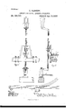
Be it known thatl, .OSCAR GASSETT, of Boston, county of Suffolk, State of Massachusetts, temporarily residing at Sewickley, county of Allegheny, State ot' Pennsylvania, have invented or discovered a new and useful Improvement in Switch and Signal Locking Apparatus; and I do hereby declare .the following to be a full, clear, concise, and exact description thereof, reference beinghad to the accompanying drawings, making a part of this specitication, in whichlike letters indicating like parts-` Fignre l shows in elevation such parts ot an electrically-locked switch-shifting mechanism as are necessary to illustrate my present invention. Fig. 2 is a sectional elevation of Fig. 1, taken a little to the right of the central vertical plane; and Fig. 3 illustrates by diagram the manner of applying or using the present improvement in combination with a railwaytrack circuit.
My present invention relates to an improved apparatus for electrically locking or unlocking the switch or signal shifting lever of a railway switch or signal apparatus, whereby the reversal of the switch or signal, after it is once properly set and after the train shall have entered upon the track-circuit, shall be effect ually prevented; and while I include as of my invention the application of the mechanism herein described to signal-lookin g purposes, I have for convenience of illustration more particularly shown it as arranged in connection with a switch-actuating lever.
A represents the lower end of a bent lever such as is employed extensively in signal and switch cabins, (commonlyin thesecond story,) and at A', I have shown the lower ends of the hangers. A vertically-moving rod, B, is em ploycd to transmit the lever motion through a bell-crank, B', tol the switch-rod B2, which may be of any known construction and connected in any known way with the movable rails r of the switch. (See Fig. 3.)
At D, Fig. 3, I have illustrated a convenient position ofthe cabin wherein this apparatus may be arranged, along with other like apparatus as may be desired, and for purposes of illustration I will assu me the presence of a like lever, as at s, by which to set the home and or is liable to pass the switch for a greater or less distance before coming to a full stop, that the switch so set -ne locked in such way that the switchman cannot, through carelessness, forgetfulness, or otherwise, reverse the switch at a time when it is too late to stop the train. To secure this desirable end I arrange on the vertical rod B a stop or shoulder, a, in suitable position to be engaged by a hook, c2, made on the armature-lever c of the armature c of an electro-magnet, P, which latter may be arranged in position and supported on the framing I or other suitable support. These dcvices are so arranged that when the electromaguet P is excited or charged it will attract the armature c, and thereby cause the hook c2 to clear the stop a, and when the electro-magnet ceases to be excited or charged the hook c2 will, under the action of a spring, e, be thrown forward into engagement with the stop a, and thereby the rod B will be locked as against a movement upward. These devices-that is to say, a stop and an armature-lever adapted to engage the same-ma y be varied at pleasure iu form, construction, and relative arrangement with reference to engaging each other, and thereby locking the rod B as against movement either upward or downward, as the work to be done may require; but as organized in thedrawings therodBis presumed to be down, and the switch thereby to be in position' for the reception of the incoming train.
The stop a may be secured to the rod B in any desired way, as by clamps and screw-bolts c' or otherwise.
The preferable-mode of using the devices described is as illustrated in Fig. 3, whereinl have shown a track-circuit formed by the line of rails w x, electrically connected one rail to another, to any desired distance-say to or pastthe distant signal-and the track-section thus formed is electrically insulated at its ends by suitable insulating material, as at av. The opposite lines of rails are connected at or near their outer ends, by wires l and 2, with the opposite poles of a battery, d, and at or near their opposite ends, by wires 3 and 4, with the opposite ends ofthe coils of the electro-magnet I?. Hence a normally-closed track-circuit is thus formed which normally will hold the hook e2 clear of the stop a; but, assuming the switch to be properly set for the reception of an incoming train, as soon as the forward 'end of such train enters on the track-section it sliertcircuits the track-circuit, so as to cut out the magnet P from the intiuence of the battery d. The result will be that the hook c2 will engage the stop a, and the rod B, and with it the lever A and the switch, will be securely locked in position, so that the switch cannot be shifted or reversed until the train shall have passed entirely off the track-section referred to. The circuit then being restored through the magnet, the lever and switch will be unlocked.
As the lever affords means of bringing a severe strain on the hook c2, I guard against breakage by carrying a stirrup, n, over the end of the armaturelevcr, and pivot the latter by a slot, i', so as to enable the armature-lever to work clear of the stirrup n in its movements, and at the same time be supported by the stirrup when any unusual strain is put on the 1ever A. The same apparatus may be applied in like manner to a signal-lever, if so desired, by connecting the wires 3 4 with an electromagnet properly arranged, as illustrated in Fig. 2, in relation to the connecting-rod of such signal-lever; and the stop ce ma)7 be arranged in any of the connecting-rods of the mechanism of the kind or class referred to.
I do not claim herein, broadly, the invention of operating the lock of a switch or signal lever by electricity; but
What I do claim is- 1. In combination with the connecting-rod of alswitcll. or signal operating mechanism, a
stop, a, arranged on such rod, an armaturc-Y o lever arranged to engage with and be disengaged from such stop, an electro-magnet, battery, and trackicircuit, substantially as set forth.
2. The stirrup n, in combination with armature-lever o and stop a on red B, substantially as set forth. v
In testimony whereof I have hereunto set my hand.
OSCAR GASSETT.
Witnesses:
R. H. WHITTLESEY, A GEORGE' H. CHRISTY.
Publications (1)
| Publication Number | Publication Date |
|---|---|
| US256797A true US256797A (en) | 1882-04-18 |
Family
ID=2326086
Family Applications (1)
| Application Number | Title | Priority Date | Filing Date |
|---|---|---|---|
| US256797D Expired - Lifetime US256797A (en) | Switch and signal locking apparatus |
Country Status (1)
| Country | Link |
|---|---|
| US (1) | US256797A (en) |
-
0
- US US256797D patent/US256797A/en not_active Expired - Lifetime
Similar Documents
| Publication | Publication Date | Title |
|---|---|---|
| US256797A (en) | Switch and signal locking apparatus | |
| US298209A (en) | Railway signaling apparatus | |
| US258601A (en) | Electric safety | |
| US529059A (en) | And michael b | |
| US530762A (en) | And george m | |
| US255998A (en) | Railway switch and signal locking apparatus | |
| US597650A (en) | morris | |
| US209042A (en) | Improvement in railway-signals | |
| US776120A (en) | Train-order protector and signal-lock. | |
| US1158665A (en) | Electric-telegraph apparatus. | |
| US283231A (en) | Electric locking mechanism for switch and signal levers | |
| US628299A (en) | Apparatus for signaling upon railways. | |
| US821767A (en) | Railway signaling system. | |
| US486047A (en) | Railway signal apparatus and system | |
| US814537A (en) | Safety device for railway switch and signal apparatus. | |
| US276138A (en) | aassett | |
| US863913A (en) | Block-signaling apparatus. | |
| US2026489A (en) | Railway traffic controlling system | |
| US837522A (en) | Automatic apparatus for controlling and operating the points of electric railways and tramways. | |
| US1102861A (en) | Signal system. | |
| US779895A (en) | Signaling-circuit for railways. | |
| US492689A (en) | Jacob william lattig | |
| US890942A (en) | Electric switch-throwing mechanism. | |
| US832192A (en) | Railway switching and signaling apparatus. | |
| US1095639A (en) | Railroad-switch. |