US2548837A - Rotating disk game device - Google Patents
Rotating disk game device Download PDFInfo
- Publication number
- US2548837A US2548837A US34369A US3436948A US2548837A US 2548837 A US2548837 A US 2548837A US 34369 A US34369 A US 34369A US 3436948 A US3436948 A US 3436948A US 2548837 A US2548837 A US 2548837A
- Authority
- US
- United States
- Prior art keywords
- slide
- pinion
- discs
- disc
- housing
- Prior art date
- Legal status (The legal status is an assumption and is not a legal conclusion. Google has not performed a legal analysis and makes no representation as to the accuracy of the status listed.)
- Expired - Lifetime
Links
Images

Classifications
-
- A—HUMAN NECESSITIES
- A63—SPORTS; GAMES; AMUSEMENTS
- A63F—CARD, BOARD, OR ROULETTE GAMES; INDOOR GAMES USING SMALL MOVING PLAYING BODIES; VIDEO GAMES; GAMES NOT OTHERWISE PROVIDED FOR
- A63F5/00—Roulette games
- A63F5/04—Disc roulettes; Dial roulettes; Teetotums; Dice-tops
- A63F5/048—Disc roulettes; Dial roulettes; Teetotums; Dice-tops with symbols viewable through holes or windows
-
- A—HUMAN NECESSITIES
- A63—SPORTS; GAMES; AMUSEMENTS
- A63F—CARD, BOARD, OR ROULETTE GAMES; INDOOR GAMES USING SMALL MOVING PLAYING BODIES; VIDEO GAMES; GAMES NOT OTHERWISE PROVIDED FOR
- A63F5/00—Roulette games
- A63F5/0094—Roulette games with a plurality of roulette wheels
-
- Y—GENERAL TAGGING OF NEW TECHNOLOGICAL DEVELOPMENTS; GENERAL TAGGING OF CROSS-SECTIONAL TECHNOLOGIES SPANNING OVER SEVERAL SECTIONS OF THE IPC; TECHNICAL SUBJECTS COVERED BY FORMER USPC CROSS-REFERENCE ART COLLECTIONS [XRACs] AND DIGESTS
- Y10—TECHNICAL SUBJECTS COVERED BY FORMER USPC
- Y10T—TECHNICAL SUBJECTS COVERED BY FORMER US CLASSIFICATION
- Y10T74/00—Machine element or mechanism
- Y10T74/19—Gearing
- Y10T74/19642—Directly cooperating gears
- Y10T74/1967—Rack and pinion
Definitions
- This invention relates to an amusement device or game, and an object is to produce a new and improved device of this character which is equipped with a plurality of discs, each having an annular row of numbers, letters or other suitable indicia, manual means being provided by which these discs may be rotated rapidly and then retained or stopped in an unpredictable position so that each time the device is operated, this indicia will be brought to view, thereby making it impossible accurately to predict the indicia displayed after each operation.
- Another object is to produce a device of this character which can be inexpensively produced on a large quantity basis, which is sturdy and reliable in construction, which may be easily assembled, and has a relatively small number of operating arts, and which can be easily operated by an unskilled person.
- Figure 2 is an edge view of the device, a portion being broken away for purposes of clarity;
- Figure 8 is a face View of the device with the cover removed
- Figure 4 is an enlarged sectional view substantially on the line 4-4 of Figure 3;
- Figure 5 is an enlarged section substantially on the line 5-5 of Figure 3;
- Figure 6 is a perspective view of the operating slide
- Figure '7 is an enlarged sectional view on the line 1'! of Figure 3;
- Figure 8 is a transverse section on the line 8-8 of Figure 4.
- Figure 9 is a perspective view of one of the ratchet arms
- Figure 10 is a perspective view of one of the rotatable discs.
- Figure 11 is a perspective view of one of the operating pinions.
- the illustrated embodiment of the invention comprises a cup-shaped cylindrical casing 10 which has a bottom wall II and a cover l2 provided with an annular flange [3 which has a snug fit against the inside of the mouth of the housing ii] the cover being retained in place by screws, as shown.
- the peripheral edges of the cover [2 and the bottom wall I l are beveled, and the housing is of relatively shallow depth so that in general the housing and cover together resemble a watch case.
- the cover I2 is formed with a rectangular sight opening [3 which is covered by a plate M of glass or other suitable transparent material, the plate being recessed substantially as shown in Figure 2- and secured in place by adhesive or any other suitable means.
- each disc is provided with an annular row of numerals which are arranged in such fashion that a numeral of each of the three discs is visible through the sight opening it through the window panel i l.
- the numerals of each of the discs are not arranged in sequence, thus to make it virtually impossible to predict the numbers appearing in the sight opening as will be more clearly understood hereinafter.
- each of the discs [5, l6 and I! is carried by i a pinion 18 which is a one-piece construction having cylindrical pin portions [9 and 2!] at opposite ends, a squared shouldered portion 2
- each of the discs has a centrally disposed squared opening 24 which fits the squared shouldered portion 2
- the pinion members [8 carryingthe discs I 5 and I! are identical with each other, but the intermediate pinion is differently constructed, the latter having the pinion adjacent the opposite end and closer to the shouldered portion 2! as shown in Figure 4.
- Each of the bottom walls of the housing wall II and the cover [2 is formed with socket portions 24 to accommodate the reduced cylindrical end portions 20 and I9.
- Each of these end portions is rotatable in a bushing 25 pressed into the respective socket and the extreme end portion is rounded as indicated at 26 ( Figure 8) to abut against a disc 2-! seated in the bottom of the socket 224 and against which the respective bushing 25 abuts.
- the reduced end portions of the pinion members [3 rotate within the bushings 25 and the rounded end portions 26 abut against the metallic disc 2'! which may be suitably hardened.
- a slide 28 is reciprocable along the inner face of the housing wall I1.
- the slide 28 consists of a flat plate having a body 29 and a reduced neck 30 which extends through the slot 3! in the side wall of the housing ii).
- the neck 30 has a shouldered end portion 32 to fit into an aperture in a flange piece 33 which is engaged by the hand for actuating the slide 28, the portion 32 being upset to retain the flange plate 33 securely in position.
- the plate 33 projects at substantially right angles to the neck 30 and in width is slightly less than the thickness of the housing l0.
- extensions Projecting laterally from the body 29 of the slide are extensions as, the upper edges of which are mounted to conform to the curvature of the side wall of the housing.
- the opposite edges of the extensions provide abutments against which the curved ends of springs 35 may abut.
- the springs 35 are of wire with the central portion coiled about the shank of screws 36 with the opposite end portion 3'! bearing against the adja cent side wall of the housing. It will be manifest that the springs 35 normally urge the slide 28 to its uppermost position ( Figure 3) with the curved portion of the extensions 34 abutting against the walls of the housing Iii.
- the lower end portion of the slide body 29 is formed with an elongate notch 38, the side walls of which are parallel to each other and engaging the bottom wall H of the housing in is a shouldered screw 39, the body of which is of sufficient diameter so that the notch 38 can slide therealong and the head of which overlaps the outer surface of the adjacent slide body.
- the screw 3! guides the longitudinal reciprocatory movement of the actuating slide 28.
- a shouldered screw 53 Mounted in the upper portion of the slide 23 in a screw-threaded aperture [it is a shouldered screw 4
- the arm Al Pivotally mounted in superposed relation on the shouldered screw 43 are arms l? and it.
- the arm Al as shown in Figure 9, has rack teeth 49 on the outer edge portion and engage with the pinion 23 which carries the disc i5. It will be observed that the rack teeth 38 and i5 occupy similar positions opposite to each other.
- the inner edge 50 of the arm M is relieved as shown throughout a substantial distance in order to clear the lower intermediate pinion 23 which carries the disc H3.
- the arm 48 adjacent its lower end portion and on the inner side has rack teeth 5! which engage the intermediate pinion 23 on which the disc 16 is mounted.
- Each of the rack arms 4-4 and t? adjacent their upper ends near their pivotal mounting, is provided with a socket to receive a coil spring 52 which yieldably urges these arms outwardly to maintain them in proper engagement with the respective pinions.
- Outward movement of the arms M and i! by the coil spring 52 is limited by guide ears 53 and 56 respectively, these ears being bent upwardly from the actuating slide 23 as shown on Figure 6.
- the rack arm as is yieldingly held in proper engagement with the intermediate pinion by a coil spring 55, one end of which is in hooked engagement with an ear 56 on the housing wall II and the opposite end hooks on a pin 51 on the upper end portion of the rack arm at.
- An ear 58 struck outwardly from the body 29 of the actuating slide 28 provides the guiding abutment against which the rack arm L13 is retained by the spring 55.
- a ring 59 is carried by a stud 50 secured to the bottom wall ll of the housing.
- the indicia on the several discs are displayed through the sight opening IS in the cover of the casing, these numbers being in horizontal alignment.
- the device may be used to advantage from an educational standpoint for the purpose of teaching children their numbers and to assist them in learning addition, for example.
- indicia other than numbers may be displayed in annular rows on the discs.
- a device of the class described comprising a casing, a cover for the casing having a single sight opening therein, three discs rotatabl mounted within said casing for rotating about parallel axes arranged in triangular relation and spaced so that the intermediate disc overlaps the other two discs, each disc having an annular row of indicia and one indicium of each disc being visible through the sight opening, a slide reciprocable within the casing rectilinearly operable between a normally extended position and an inwardly retracted position, a finger piece fixed to said slide for operating same, cooperating means on the casing and slide for guiding the rectilinear movements of the latter, spring means engaged between the slide and casing for normally holding said slide in its extended position, three arms each pivoted at one end to said slide and extending generally in the direction of the length thereof, two of said arms having a common axis and being arranged in superposed position, a pinion fixed to and co-axial with each disc, each of said arms including rack tooth and smooth portions extending
Description
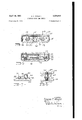
April 10, 1951 wRlGHT 2,548,837
ROTATING DISK GAME DEVICE Filed June 22, 1948 2 Sheets-Sheet l fl i315 a? INVENTOR. EE A225? W5LHT fI -lfifILi-ll- [MM ML 1 ATTK April 10, 1951 E. F. WRIGHT 2,548,337
ROTATING DISK GAME DEVICE Filed June 22, 1948 v 2 Sheets-Sheet 2 TIE-5- 3;
JQNVENTOR.
E17 WARD F W?HT B WW1. W
ATTY. I
Patented Apr. 10, 1951 UNITED STATES PATENT OFFICE ROTATING DISK GAME DEVICE Edward F. Wright, Toledo, Ohio Application June 22, 1948, Serial No. 34,369
1 Claim. 1
This invention relates to an amusement device or game, and an object is to produce a new and improved device of this character which is equipped with a plurality of discs, each having an annular row of numbers, letters or other suitable indicia, manual means being provided by which these discs may be rotated rapidly and then retained or stopped in an unpredictable position so that each time the device is operated, this indicia will be brought to view, thereby making it impossible accurately to predict the indicia displayed after each operation.
Another object is to produce a device of this character which can be inexpensively produced on a large quantity basis, which is sturdy and reliable in construction, which may be easily assembled, and has a relatively small number of operating arts, and which can be easily operated by an unskilled person.
Other objects and advantages of the invention will hereinafter appear, and for purposes of illustration but not of limitation, an embodiment of the invention is shown on the accompanying drawings, in which Figure 1 is a face view of the amusement device or game;
Figure 2 is an edge view of the device, a portion being broken away for purposes of clarity;
Figure 8 is a face View of the device with the cover removed;
Figure 4 is an enlarged sectional view substantially on the line 4-4 of Figure 3;
Figure 5 is an enlarged section substantially on the line 5-5 of Figure 3;
Figure 6 is a perspective view of the operating slide;
Figure '7 is an enlarged sectional view on the line 1'! of Figure 3;
Figure 8 is a transverse section on the line 8-8 of Figure 4;
Figure 9 is a perspective view of one of the ratchet arms;
Figure 10 is a perspective view of one of the rotatable discs; and
Figure 11 is a perspective view of one of the operating pinions.
The illustrated embodiment of the invention comprises a cup-shaped cylindrical casing 10 which has a bottom wall II and a cover l2 provided with an annular flange [3 which has a snug fit against the inside of the mouth of the housing ii] the cover being retained in place by screws, as shown. The peripheral edges of the cover [2 and the bottom wall I l are beveled, and the housing is of relatively shallow depth so that in general the housing and cover together resemble a watch case. The cover I2 is formed with a rectangular sight opening [3 which is covered by a plate M of glass or other suitable transparent material, the plate being recessed substantially as shown in Figure 2- and secured in place by adhesive or any other suitable means.
Directly in rear of the cover l2 are three discs [5, l6 and I! of any suitable sheet material, the arrangement being such that the discs [5 and I! have their axes in alignment and the disc [6 has its axis offset between the axes of the other discs so as to be in overlapping relation to the other discs. In this instance, each disc is provided with an annular row of numerals which are arranged in such fashion that a numeral of each of the three discs is visible through the sight opening it through the window panel i l. The numerals of each of the discs are not arranged in sequence, thus to make it virtually impossible to predict the numbers appearing in the sight opening as will be more clearly understood hereinafter.
Each of the discs [5, l6 and I! is carried by i a pinion 18 which is a one-piece construction having cylindrical pin portions [9 and 2!] at opposite ends, a squared shouldered portion 2| adjacent the pin 19, an elongate cylindrical bearing portion 22, and a pinion 23. As shown in Figure 10, each of the discs has a centrally disposed squared opening 24 which fits the squared shouldered portion 2| of the pinion member so that the disc rotates with the pinion member. The pinion members [8 carryingthe discs I 5 and I! are identical with each other, but the intermediate pinion is differently constructed, the latter having the pinion adjacent the opposite end and closer to the shouldered portion 2! as shown in Figure 4.
Each of the bottom walls of the housing wall II and the cover [2 is formed with socket portions 24 to accommodate the reduced cylindrical end portions 20 and I9. Each of these end portions is rotatable in a bushing 25 pressed into the respective socket and the extreme end portion is rounded as indicated at 26 (Figure 8) to abut against a disc 2-! seated in the bottom of the socket 224 and against which the respective bushing 25 abuts. Thus the reduced end portions of the pinion members [3 rotate within the bushings 25 and the rounded end portions 26 abut against the metallic disc 2'! which may be suitably hardened.
For actuating the pinion members l8, a slide 28 is reciprocable along the inner face of the housing wall I1. The slide 28 consists of a flat plate having a body 29 and a reduced neck 30 which extends through the slot 3! in the side wall of the housing ii). The neck 30 has a shouldered end portion 32 to fit into an aperture in a flange piece 33 which is engaged by the hand for actuating the slide 28, the portion 32 being upset to retain the flange plate 33 securely in position. As shown, the plate 33 projects at substantially right angles to the neck 30 and in width is slightly less than the thickness of the housing l0.
Projecting laterally from the body 29 of the slide are extensions as, the upper edges of which are mounted to conform to the curvature of the side wall of the housing. The opposite edges of the extensions provide abutments against which the curved ends of springs 35 may abut. The springs 35 are of wire with the central portion coiled about the shank of screws 36 with the opposite end portion 3'! bearing against the adja cent side wall of the housing. It will be manifest that the springs 35 normally urge the slide 28 to its uppermost position (Figure 3) with the curved portion of the extensions 34 abutting against the walls of the housing Iii. The lower end portion of the slide body 29 is formed with an elongate notch 38, the side walls of which are parallel to each other and engaging the bottom wall H of the housing in is a shouldered screw 39, the body of which is of sufficient diameter so that the notch 38 can slide therealong and the head of which overlaps the outer surface of the adjacent slide body. In this manner, the screw 3!; guides the longitudinal reciprocatory movement of the actuating slide 28.
Mounted in the upper portion of the slide 23 in a screw-threaded aperture [it is a shouldered screw 4| and spaced laterally therefrom and engaging in a screw-threaded aperture 62 in the slide 28 is a shouldered screw 53. Particularly as shown in Figure 7, it Will be observed that the shouldered screw is is approximately twice the length of the screw 4i. Pivotally mounted on the shouldered screw 4! is an arm Ml, the outer edge of which is formed with rack teeth A5 to engage the pinion 23 which carries the disc i l. The lower portion of the arm td on the inner side is relieved as indicated at 48 so that during the reciprocating movement of the slide 28, it will not interfere with the intermediate pinion carrying the disc l6.
Pivotally mounted in superposed relation on the shouldered screw 43 are arms l? and it. The arm Al as shown in Figure 9, has rack teeth 49 on the outer edge portion and engage with the pinion 23 which carries the disc i5. It will be observed that the rack teeth 38 and i5 occupy similar positions opposite to each other. The inner edge 50 of the arm M is relieved as shown throughout a substantial distance in order to clear the lower intermediate pinion 23 which carries the disc H3. The arm 48 adjacent its lower end portion and on the inner side has rack teeth 5! which engage the intermediate pinion 23 on which the disc 16 is mounted.
Each of the rack arms 4-4 and t? adjacent their upper ends near their pivotal mounting, is provided with a socket to receive a coil spring 52 which yieldably urges these arms outwardly to maintain them in proper engagement with the respective pinions. Outward movement of the arms M and i! by the coil spring 52 is limited by guide ears 53 and 56 respectively, these ears being bent upwardly from the actuating slide 23 as shown on Figure 6. The rack arm as is yieldingly held in proper engagement with the intermediate pinion by a coil spring 55, one end of which is in hooked engagement with an ear 56 on the housing wall II and the opposite end hooks on a pin 51 on the upper end portion of the rack arm at. An ear 58 struck outwardly from the body 29 of the actuating slide 28 provides the guiding abutment against which the rack arm L13 is retained by the spring 55.
From the above description, it will be manifest that by pushing down on the flange plate 33, the rack arms impart rotative movement to the pinion member l8, the two outer pinions being rotated in a counterclockwise direction and the intermediate pinion in a clockwise direction. After the rack teeth become disengaged from the pinions, the several pinion members can rotate freely. Then when the flange plate 33 is released allowing the springs 35 to return the actuating slide 28 to its normal position, the rack teeth again engage the pinion and thereby lock the several discs against further rotative movement.
To assist in holding the housing during the actuation of the slide 28, a ring 59 is carried by a stud 50 secured to the bottom wall ll of the housing.
In the operation of the device above described, it will be manifest that by depressin the flange plate 33 to reciprocate the slide 28, the rack and pinion connection is such as to rotate rapidly the several discs. After the slide has been sufiiciently actuated so that the rack teeth are moved out of engagement with the pinion, the discs continue to rotate due to their momentum. Then, upon releasing the flange plate 33, the springs 35 retract the slide 28 to its normal position and in so doing, the rack teeth again engage the pinion and in the final position of rest of the actuating slide, the pinions and their discs are positively retained and held against further retractive movement. At such time, the indicia on the several discs, numbers, for example, are displayed through the sight opening IS in the cover of the casing, these numbers being in horizontal alignment. Thus in the use of the device, a person may guess as to the numbers which will eventually be displayed through the sight openin so that the'device may be used as a guessin game. On the other hand, the device may be used to advantage from an educational standpoint for the purpose of teaching children their numbers and to assist them in learning addition, for example. Of course, as above indicated, indicia other than numbers may be displayed in annular rows on the discs.
It is to be understood that numerous changes in details of construction, arrangement and operation may be effected without departing from the spirit of the invention especially as defined in the appended claim.
What I claim is:
A device of the class described, comprising a casing, a cover for the casing having a single sight opening therein, three discs rotatabl mounted within said casing for rotating about parallel axes arranged in triangular relation and spaced so that the intermediate disc overlaps the other two discs, each disc having an annular row of indicia and one indicium of each disc being visible through the sight opening, a slide reciprocable within the casing rectilinearly operable between a normally extended position and an inwardly retracted position, a finger piece fixed to said slide for operating same, cooperating means on the casing and slide for guiding the rectilinear movements of the latter, spring means engaged between the slide and casing for normally holding said slide in its extended position, three arms each pivoted at one end to said slide and extending generally in the direction of the length thereof, two of said arms having a common axis and being arranged in superposed position, a pinion fixed to and co-axial with each disc, each of said arms including rack tooth and smooth portions extending serially therealong, said rack tooth portions being arranged to mesh with said pinions, each of said rack tooth portions lying opposite to and meshingly engaging a pinion in the normal extended position of the slide, each of said smooth portions lying opposite to a pinion in the retracted position of the slide, spring means respectively urging the arms toward their respective pinions, whereby rectilinear movement of the slide, by pressing upon the finger piece, causes simultaneous rotation of each of the discs, the latter spinning freely after being disengaged from the rack teeth and whereby upon release of the finger piece and movement toward its extended position the rack teeth affirmatively re-engage and rotate their respective pinions in the opposite direction and upon reaching the normally extended position of the slide, said rack teeth positively hold the pinions against further rotation. EDWARD F. WRIGHT.
REFERENCES CITED The following references are of record in the file of this patent:
UNITED STATES PATENTS
Priority Applications (1)
| Application Number | Priority Date | Filing Date | Title |
|---|---|---|---|
| US34369A US2548837A (en) | 1948-06-22 | 1948-06-22 | Rotating disk game device |
Applications Claiming Priority (1)
| Application Number | Priority Date | Filing Date | Title |
|---|---|---|---|
| US34369A US2548837A (en) | 1948-06-22 | 1948-06-22 | Rotating disk game device |
Publications (1)
| Publication Number | Publication Date |
|---|---|
| US2548837A true US2548837A (en) | 1951-04-10 |
Family
ID=21875983
Family Applications (1)
| Application Number | Title | Priority Date | Filing Date |
|---|---|---|---|
| US34369A Expired - Lifetime US2548837A (en) | 1948-06-22 | 1948-06-22 | Rotating disk game device |
Country Status (1)
| Country | Link |
|---|---|
| US (1) | US2548837A (en) |
Cited By (8)
| Publication number | Priority date | Publication date | Assignee | Title |
|---|---|---|---|---|
| US2749657A (en) * | 1953-09-08 | 1956-06-12 | Hallmark Cards | Animated card |
| US2793037A (en) * | 1954-05-17 | 1957-05-21 | Luther A Smith | Indoor golf equipment |
| US2875553A (en) * | 1952-09-17 | 1959-03-03 | Morgan Dev Lab Inc | Color changing spinning toy |
| US2957625A (en) * | 1960-10-25 | Certificate of correction | ||
| US3493172A (en) * | 1968-08-19 | 1970-02-03 | Iliffe Ntp Inc | Counting device |
| US4167830A (en) * | 1977-05-06 | 1979-09-18 | Takara Co., Ltd. | Random indicator amphibious vehicle assembly |
| US4669328A (en) * | 1984-09-14 | 1987-06-02 | Victor Company Of Japan, Ltd. | Feed mechanism |
| US5918880A (en) * | 1995-02-09 | 1999-07-06 | Fundex Games, Ltd. | Game playing apparatus |
Citations (6)
| Publication number | Priority date | Publication date | Assignee | Title |
|---|---|---|---|---|
| US518726A (en) * | 1894-04-24 | Coin-controlled game | ||
| US536526A (en) * | 1895-03-26 | Blackboard | ||
| US925534A (en) * | 1908-04-02 | 1909-06-22 | Charles L Tuthill | Game apparatus. |
| GB191022020A (en) * | 1910-09-22 | 1911-08-03 | Edward Moriarty | A New or Improved Device for Indicating the Opening Moves in Chess, Draughts, and similar Games. |
| US1010652A (en) * | 1911-02-18 | 1911-12-05 | Edward Locke | Swing-operated motor. |
| CH177624A (en) * | 1933-05-08 | 1935-06-15 | Calame Charles | Semi-automatic game. |
-
1948
- 1948-06-22 US US34369A patent/US2548837A/en not_active Expired - Lifetime
Patent Citations (6)
| Publication number | Priority date | Publication date | Assignee | Title |
|---|---|---|---|---|
| US518726A (en) * | 1894-04-24 | Coin-controlled game | ||
| US536526A (en) * | 1895-03-26 | Blackboard | ||
| US925534A (en) * | 1908-04-02 | 1909-06-22 | Charles L Tuthill | Game apparatus. |
| GB191022020A (en) * | 1910-09-22 | 1911-08-03 | Edward Moriarty | A New or Improved Device for Indicating the Opening Moves in Chess, Draughts, and similar Games. |
| US1010652A (en) * | 1911-02-18 | 1911-12-05 | Edward Locke | Swing-operated motor. |
| CH177624A (en) * | 1933-05-08 | 1935-06-15 | Calame Charles | Semi-automatic game. |
Cited By (9)
| Publication number | Priority date | Publication date | Assignee | Title |
|---|---|---|---|---|
| US2957625A (en) * | 1960-10-25 | Certificate of correction | ||
| US2875553A (en) * | 1952-09-17 | 1959-03-03 | Morgan Dev Lab Inc | Color changing spinning toy |
| US2749657A (en) * | 1953-09-08 | 1956-06-12 | Hallmark Cards | Animated card |
| US2793037A (en) * | 1954-05-17 | 1957-05-21 | Luther A Smith | Indoor golf equipment |
| US3493172A (en) * | 1968-08-19 | 1970-02-03 | Iliffe Ntp Inc | Counting device |
| US4167830A (en) * | 1977-05-06 | 1979-09-18 | Takara Co., Ltd. | Random indicator amphibious vehicle assembly |
| US4669328A (en) * | 1984-09-14 | 1987-06-02 | Victor Company Of Japan, Ltd. | Feed mechanism |
| US5918880A (en) * | 1995-02-09 | 1999-07-06 | Fundex Games, Ltd. | Game playing apparatus |
| US6431548B1 (en) | 1995-02-09 | 2002-08-13 | Fundex Games, Ltd. | Game playing apparatus |
Similar Documents
| Publication | Publication Date | Title |
|---|---|---|
| JP3013649U (en) | Magnetic pen | |
| US2548837A (en) | Rotating disk game device | |
| US4368381A (en) | Numeral adding toy | |
| US3690021A (en) | Toy clock | |
| US4798555A (en) | Toy pop-up figure | |
| US2187664A (en) | Mechanical rosary | |
| US2280623A (en) | Game or toy of skill | |
| US3765120A (en) | Toy toaster | |
| US2981963A (en) | Brush with stroke counter | |
| US1970586A (en) | Game device | |
| US2556304A (en) | Doll head with simulated growing teeth | |
| US3535818A (en) | Doll with growing tooth | |
| US2113274A (en) | Alarm interval timer | |
| US4179825A (en) | Apparatus for teaching numerical concepts | |
| GB531294A (en) | Improvements in coin-operated mechanism | |
| US1514524A (en) | Recording instrument | |
| US1949942A (en) | Clock | |
| US2460549A (en) | stiles | |
| US1944629A (en) | Golf register | |
| US1774157A (en) | Arm attachment for indicators | |
| US1421801A (en) | Repeater timepiece | |
| US1618488A (en) | stockwell | |
| JPH0611796U (en) | Moving toys | |
| US1692729A (en) | Clock and time controlled switch for electric lights | |
| US2541903A (en) | Automatically selective indexed memorandum device |