US2544161A - Compression valve - Google Patents
Compression valve Download PDFInfo
- Publication number
- US2544161A US2544161A US663266A US66326646A US2544161A US 2544161 A US2544161 A US 2544161A US 663266 A US663266 A US 663266A US 66326646 A US66326646 A US 66326646A US 2544161 A US2544161 A US 2544161A
- Authority
- US
- United States
- Prior art keywords
- valve
- bore
- operating
- seat
- pin
- Prior art date
- Legal status (The legal status is an assumption and is not a legal conclusion. Google has not performed a legal analysis and makes no representation as to the accuracy of the status listed.)
- Expired - Lifetime
Links
- 230000006835 compression Effects 0.000 title description 7
- 238000007906 compression Methods 0.000 title description 7
- 238000010276 construction Methods 0.000 description 9
- 239000012530 fluid Substances 0.000 description 9
- 230000002093 peripheral effect Effects 0.000 description 9
- 239000007788 liquid Substances 0.000 description 5
- 239000008267 milk Substances 0.000 description 5
- 210000004080 milk Anatomy 0.000 description 5
- 235000013336 milk Nutrition 0.000 description 5
- 230000004044 response Effects 0.000 description 5
- 238000004140 cleaning Methods 0.000 description 4
- 235000013305 food Nutrition 0.000 description 2
- 230000002452 interceptive effect Effects 0.000 description 2
- 230000007246 mechanism Effects 0.000 description 2
- 238000000034 method Methods 0.000 description 2
- 230000008439 repair process Effects 0.000 description 2
- 238000007789 sealing Methods 0.000 description 2
- 239000007787 solid Substances 0.000 description 2
- 102100027069 Odontogenic ameloblast-associated protein Human genes 0.000 description 1
- 101710091533 Odontogenic ameloblast-associated protein Proteins 0.000 description 1
- 230000015572 biosynthetic process Effects 0.000 description 1
- 230000008859 change Effects 0.000 description 1
- 230000008030 elimination Effects 0.000 description 1
- 238000003379 elimination reaction Methods 0.000 description 1
- 239000000463 material Substances 0.000 description 1
- 239000002184 metal Substances 0.000 description 1
- 230000004048 modification Effects 0.000 description 1
- 238000012986 modification Methods 0.000 description 1
- 238000012856 packing Methods 0.000 description 1
- XRKMYXDEMOEFBN-UHFFFAOYSA-N potassium;[2-butyl-5-chloro-3-[[4-[2-(1,2,3-triaza-4-azanidacyclopenta-2,5-dien-5-yl)phenyl]phenyl]methyl]imidazol-4-yl]methanol;6-chloro-1,1-dioxo-3,4-dihydro-2h-1$l^{6},2,4-benzothiadiazine-7-sulfonamide Chemical compound [K+].C1=C(Cl)C(S(=O)(=O)N)=CC2=C1NCNS2(=O)=O.CCCCC1=NC(Cl)=C(CO)N1CC1=CC=C(C=2C(=CC=CC=2)C=2[N-]N=NN=2)C=C1 XRKMYXDEMOEFBN-UHFFFAOYSA-N 0.000 description 1
- 230000009467 reduction Effects 0.000 description 1
- 230000000717 retained effect Effects 0.000 description 1
- 238000000926 separation method Methods 0.000 description 1
- 229910001220 stainless steel Inorganic materials 0.000 description 1
- 239000010935 stainless steel Substances 0.000 description 1
- 239000000126 substance Substances 0.000 description 1
Images

Classifications
-
- F—MECHANICAL ENGINEERING; LIGHTING; HEATING; WEAPONS; BLASTING
- F16—ENGINEERING ELEMENTS AND UNITS; GENERAL MEASURES FOR PRODUCING AND MAINTAINING EFFECTIVE FUNCTIONING OF MACHINES OR INSTALLATIONS; THERMAL INSULATION IN GENERAL
- F16K—VALVES; TAPS; COCKS; ACTUATING-FLOATS; DEVICES FOR VENTING OR AERATING
- F16K31/00—Actuating devices; Operating means; Releasing devices
- F16K31/44—Mechanical actuating means
- F16K31/52—Mechanical actuating means with crank, eccentric, or cam
- F16K31/528—Mechanical actuating means with crank, eccentric, or cam with pin and slot
Definitions
- This invention relates to improvements in compression valves.
- valve with which the present invention is concerned is particularly adapted for use in connection with milk pasteurizing equipment and for use in other places where a high degree of sanitation is required.
- Valves used in pas teurizing equipment must be removed and taken apart daily for cleaning. For this reason it is important that the parts have a minimum of food catching projections and that they be readily separable so that removal and cleaning can be quickly effected and reassembly accomplished without loss of valuable time.
- valve member In a straightway compression type of valve with which the present invention is particularly concerned, the valve member is movable axially of the fluid conducting conduit, and there are usually two axially alined bore portions of Vdifferent diameter in order to make it possible to form a valve seat. Where the valve seat is thus formed it has been common practice to provide a relatively large diierence in the diameter between the two bore portions so that the valve opening will be substantially lessened.
- a valve member of sufficiently small diameter may be used to provide for free flow of material between the periphery of the valve member and the wall of the conduit when the valve is open. Where such a small valve member is employed, however, there must be guiding wings or iins to keep the valve member centered and to support it for sliding movement.
- valve opening is relatively small and where there is a relatively large difference in diameter between the two bore portions, there is necessarily a relatively large annular shoulder behind which milk solids can collect to contaminate the equipment.
- a valve,V therefore, as commonly constructed, is objectionable for use in the food industry or for other uses where sanitation is a factor.
- 1t is a general object of the present invention to provide a valve of the class described which provides two alined bore portions with a very small difference in diameter, just sufficient to' form a valve seat without having a large shoulder to trap milk or other fluid, which nevertheless provides for the free ow of milk or similar liquid past the periphery of the valve member, when the latter is open, with a minimum of obstruction to the ow.
- a more specilic object of the invention is to accomplish the above purpose in the combination by having the tubular valve body extension,
- valve operating assembly which accommodates the valve operating assembly, of substantially larger diameter than the conduit with which it connects whereby there will be relatively large bulges on each side of the conduit furnishing spaces between said bulges and the periphery of the valve member to permit liquids to readily pass through said spaces when the valve member is open.
- diameter of the valve disk relatively small to provide suicient space around the periphery thereof.
- a further object of the invention is to provide in a sanitary valve oi the class described, relatively simple means for eliminating the nut normally employed on the end of the body extension, said means serving to releasably maintain the valve operating assembly and handle in assembled position while providing for the quick separation or assembly of parts for cleaning or repair.
- a more specific object of the invention is to provide a construction as above described wherein there is a cylindrical collar at the inner end of the handle which is rotatable within a tubular extension of the valve body and which carries a crank pin for -operating the valve, the collar and tubular extension having cooperating pin and slot means which permits rotating movement of the collar for valve operating purposes but which prevents accidental removal of the operating assembly.
- the invention consists of the improved compression valve, and all its parts and combinations, as set forth in the claims, and all equivalents thereof.
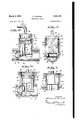
- Fig. 1 is a longitudinal sectional View through the valve body illustrating the operating parts therein with the valve member in closed position;
- Fig. 2 is a sectional view taken on line 2-2 of Fig. 1;
- Fig. 3 is a view similar to Fig. 1 illustrating the valve in open position, rparts of the valve body being broken away;
- Fig. 4 is a view similar to Fig. 3, showing the operating -assembly as it is being inserted or as it is being removed;
- Fig. is a sectional view taken approximately on the line 5 5 of Fig. but showing the pin engaged in the entrance groove portion;
- Fig. 6 is a view similar to Fig. 1, illustrating a modified construction, parts being broken away;
- Fig. 7 is a fragmentary longitudinal sectional view showing a modication of the construction of Fig. ⁇ 5.
- the numeral IS designates the valve body which is formed of suitable metal, usually of stainless steel, when the valve is e'm ployed in pasteurizing equipment.
- the valve body includes a main conduit portion ll and a tubular extension i2 which joins the conduit portion i l at approximately right angles thereto.
- the internal bore portion I3 of the conduit H has a normal diameter.
- the internal bore portion M is of tapered formation to re- The seat iti is just enough to form a suitable seat.
- valve seat l5 isformed without the use or any large or premi nent shoulder or without any great change in diameter.
- the valve member-I6 may be of sufficient diameter to have a snug sliding With prior constructions such a snug fit of the valve in the bore portion i3 would hinder the passage of i-luid around the periphery of the valve and into the bore portion i3.
- valve member may be made substantially the diameter of -the bore portion I3 without preventing free flow of liquid through the conduit i@ and Without interfering with free drainage. This is accomplished by having the tubular extension i2 of substantially larger diameter than the conduit portion l!! instead of having it of the same diameter as has heretofore been common practice. By having it of substantially larger diameter there are bulges il (see Fig.
- a short bar 2t Projecting rearwardly from the valve member E5 is a short bar 2t having a transverse slot ZI.
- the bar forms a valve stem.
- the valve operating assembly includes a handle 22 having a cylindrical collar 23 integral with the handle portion 24 and concentric therewith.
- the external diameter of the cylindrical collar 23 is slightly less than the internal diameter of the valve body extension i2 so that thecollar is rotatable therein.
- the collar may be formed with a peripheral recess 25 for accommodating a suitable packing ring 26.
- the recess is of substantial width so that rings 26 of selected width may be employed. For example, if an easy turning valve is desired, a narrow gasket willbe used.
- a collar locking gro-ove 2l which is cooperable with a pin 2B projecting from the wallof the extension l2.
- The. groove 2l includes a short axially extending entrance portion 29 which is open as at 35.
- the pin may be made to enter the portion 29 when the operating assembly is being inserted in the extension l2 while the parts are in the position of Fig. 4.
- the pin will travel in a peripheral groove portion 3
- the handle is swung from the position of Fig. 1 to the position of Fig. 3. Therefore, during both valve opening and valve closing movements, the pin 23 is in engagement Vwith the peripheral groove portion33 only.
- the operating assembly is .maintained in position in the valve opera-ting extension l2 without the use of the usual nut on the upper end of the extension,.thereby eliminating one part and facilitating disassembly for cleaning purposes or repair. It is, ofcourse, understood that the pin and slot construction may be reverse-'l if: desired so that 4thegroove is on the body extension I2 and the pin on the member 23.
- the construction is the same as in the form of the invention just described, except for the method of retaining the operating assembly in assem.. bled position.
- the same reference numerals are employed to designate all of the -parts which are common to the parts of Figs. 1 to extension i2.
- the upper end of the cylindrical collar 23 has a laterally projecting annular ange 35 which engages an annular seat 36 formed by enlarging the bore of the cylindrical extension i2 at the upper end thereof.
- the operating assembly is maintained in position by a nut 3l which has a threaded connection with the end of the tubular extension I2.
- the nut has a central opening 38 through which the uppermost portion yof the cylindrical collar 23 rotatably projects, and the annular ange 35 projects beyond the marginal edge of the opening 38.
- a tubular body portion forming a fluid conduit and having yaxially alined inlet and outlet portions of diierent bore diameters to provide a valve seat therebetween
- a valve member having e. circular portion of substantially the same diameter as the larger bore portion and coaxial therewith and movable axially therein into and out of engagement with said seat, there being portions of said larger bore engaged by the periphery of said circular valve portion throughout the length of movement of said valve
- a tubular extension projecting at an angle from said body portion adjacent said seat and between said inlet and outlet portions, said extension having a bore portion of greater diameter than the larger bore portion of the tubular body to produce oppositely disposed bulges at the juncture between said tubular extension and tubular body portion, said "E bulges being located on each side of the valve member when the latter is in open position, and valve operating mechanism having a portion located in said tubular extension.
- a tubular body portion forming a fluid conduit and having a bore formed with a valve seat, a valve member movable axially of said bore into and out of engagement with said seat, a tubular extension projecting at an angle from said body portion adjacent said seat and having a pin projecting inwardly from its bore, a cylindrical valve operating member rotatable in said tubular extension, said operating member having a peripheral groove engaged by said pin, said groove having an open ended assembly portion and having an oiset valve operating portion communicating with said assembly portion whereby said operating member is normally maintained in operative position.
- a tubular body portion forming a fluid conduit and having a bore formed with an annular tapered valve seat
- a valve member having a circular portion of substantially the same diameter as said bore and coaxial therewith and having a conical portion, said valve member being movable axially in the bore to bring the conical portion into and out of engagement with the tapered valve seat, there being portions of said bore engaged by the periphery of said circular valve portion throughout the length of movement of said valve
- a tubular extension projecting at an angle from said body portion adjacent said seat, said extension having a bore portion of greater diameter than said bore of the tubular body to produce oppositely disposed bulges at the juncture between said tubular extension and tubular body portion, said bulges being located on each side of the valve member when the latter is in open position, and valve operating mechanism having a portion located in said tubular extension.
- a tubular body portion forming a iiuid conduit and having a bore formed with a Valve seat, ia valve member movable axially of said bore into and out of engagement with said seat, a tubular extension projecting at an angle from said body portion adjacent said seat and having -a pin projecting inwardly from its bore, a cylindrical valve operating member rotatable in said tubular extension, means projecting from theA inner end of said operating member and removably engageable ywith the valve member for actuating the latter in response to rotation of the operating member, said operating member having a peripheral groove eng-aged by said pin and said groove having an open ended assembly portion and having an olset valve operating portion communicating with said assembly portion.
- a tubular body portion forming a fluid conduit and having a bore formed with a valve seat, a valve member movable axially of said .bore into and out of engagement with said seat, a tubular extension projecting at an angle from said body portion adjacent said seat and having a pin projecting inwardly from its bore, a cylindrical valve operating member rotatable in said tubular extension, means projecting from the inner end of said operating member and removably engageable with the valve member for actuating the latter in response to rotation of the operating member, said operating member having a peripheral groove engaged by said pin and said groove having an open ended entrance portion extending from the inner end of the operating 'membere having aucircumferentially extending portionextending part way around'the operating member andfhavingv a second circumierentially extending portion Whichis axially offset from vsaid rst circumferentially extending portion 6."
- a :tubular body Yportieri forming a fluid conduit and having a bore formed with a valve seat
- valve operating .member rotatable in said tubular extension, means projecting from 'the inner end of said operating member and removably engageable with the valve member for actuating the latter in response to rotation of the operating member, and pin and groove means for guiding the operating member into operating position in said tubular extension, saidrmeans including an offset groove portion for preventing accidental disengagement.
- a tubular body portion formed with a valve seat, a valve member movable into and out of engagement with said seat, a tubular extension projecting at an angle from said body portion-adjacent said seat and having apin pro jectinginwardly from its bore, a cylindrical valve operating member rotatable in said tubular eX- tension, and means projecting from the inner end of said operating member and removably engageable with the valve member for actuating the latter in response to the rotation of the operating member, said operatingmember having a peripheral groove engaged by said pin, and said groove having anopen ended assembly portion and hav.- ingan offset valveoperating portion communicating with said assembly portion.
- a tubular body portion forming a .fluid conduit and having a bore formed with a valve seat, a valve member movable into and out of engagement with saidseat, atubular extensionA projecting at anangle from said body portion adjacentsaid seat, Aa cylindrical valve vop- 8 eratingmemberrotatable in said tubular extension, means projectingirorn. the Ainner end of said .operating 'member and removably engageable with the valve member for actuating the latter in yresponse to .rotation of the operating member, and pin and groove means for .guiding the operating member into operating position. in .said tubularxextension, said meansincluding an offset grooveportion for preventing accidental disengagement.
- atubular body formingA a nuid conduit andfhaving abore formedwith a valve seat, a Vvalve memberymovablecinto and out. of engagement with said seat, va cylindrical valve operating member rotatable in said body, a pin projecting inwardly from the interior of said body adjacent said operai-,ing member, and means projecting lfrom the: inner end of said operating member and connected tothe valve member for .actuating the latter in response to rotation of the operating member, said, operating member having a peripheral groove engaged by said pin, and said groove having an open ended assembly portion and having an oiset valve operating portion communicating with said assembly portion whereby said operating member is'normally retained in operative position.
Landscapes
- Engineering & Computer Science (AREA)
- General Engineering & Computer Science (AREA)
- Mechanical Engineering (AREA)
- Lift Valve (AREA)
Description
March 6, 1951 F. HlNRlcHs 2,544,151
' CoMPREssIoN VALVE Filed April 19, 1946 2 Sheets-Sheet l March 5, 1951 F. HlNRlcHs coMPREssIoN VALVE Filed April l, 1946 2 Sheets-Sheet 2 mw m mw MMA l Patented Mar. 6, 1.951
COMPRESSION VALVE Ferdinand Hinrichs, Kenosha, Wis., assignor to Tri-Clover Machine Co., Kenosha, Wis., a corporation of Wisconsin Application April 19, 1946, Serial No. 663,266
9 Claims. l
This invention relates to improvements in compression valves.
The valve with which the present invention is concerned is particularly adapted for use in connection with milk pasteurizing equipment and for use in other places where a high degree of sanitation is required. Valves used in pas teurizing equipment must be removed and taken apart daily for cleaning. For this reason it is important that the parts have a minimum of food catching projections and that they be readily separable so that removal and cleaning can be quickly effected and reassembly accomplished without loss of valuable time.
In a straightway compression type of valve with which the present invention is particularly concerned, the valve member is movable axially of the fluid conducting conduit, and there are usually two axially alined bore portions of Vdifferent diameter in order to make it possible to form a valve seat. Where the valve seat is thus formed it has been common practice to provide a relatively large diierence in the diameter between the two bore portions so that the valve opening will be substantially lessened. Thus, a valve member of sufficiently small diameter may be used to provide for free flow of material between the periphery of the valve member and the wall of the conduit when the valve is open. Where such a small valve member is employed, however, there must be guiding wings or iins to keep the valve member centered and to support it for sliding movement. Furthermore, where the valve opening is relatively small and where there is a relatively large difference in diameter between the two bore portions, there is necessarily a relatively large annular shoulder behind which milk solids can collect to contaminate the equipment. Such a valve,V therefore, as commonly constructed, is objectionable for use in the food industry or for other uses where sanitation is a factor.
1t is a general object of the present invention to provide a valve of the class described which provides two alined bore portions with a very small difference in diameter, just sufficient to' form a valve seat without having a large shoulder to trap milk or other fluid, which nevertheless provides for the free ow of milk or similar liquid past the periphery of the valve member, when the latter is open, with a minimum of obstruction to the ow.
A more specilic object of the invention is to accomplish the above purpose in the combination by having the tubular valve body extension,
which accommodates the valve operating assembly, of substantially larger diameter than the conduit with which it connects whereby there will be relatively large bulges on each side of the conduit furnishing spaces between said bulges and the periphery of the valve member to permit liquids to readily pass through said spaces when the valve member is open. Heretofore it has been necessary to have the diameter of the valve disk relatively small to provide suicient space around the periphery thereof.
A further object of the invention is to provide in a sanitary valve oi the class described, relatively simple means for eliminating the nut normally employed on the end of the body extension, said means serving to releasably maintain the valve operating assembly and handle in assembled position while providing for the quick separation or assembly of parts for cleaning or repair. f,
A more specific object of the invention is to provide a construction as above described wherein there is a cylindrical collar at the inner end of the handle which is rotatable within a tubular extension of the valve body and which carries a crank pin for -operating the valve, the collar and tubular extension having cooperating pin and slot means which permits rotating movement of the collar for valve operating purposes but which prevents accidental removal of the operating assembly.
Other objects of the invention are to provide a valve which is relatively simple in construction, which has a minimum number of parts, which is positive in operation, and which is otherwise well adapted for the purpose described.
With the above and other objects in view, the invention consists of the improved compression valve, and all its parts and combinations, as set forth in the claims, and all equivalents thereof.
In the accompanying drawings, illustrating several embodiments oi the invention, in which the same reference numerals designate the same parts in all of the views:
Fig. 1 is a longitudinal sectional View through the valve body illustrating the operating parts therein with the valve member in closed position;
Fig. 2 is a sectional view taken on line 2-2 of Fig. 1;
Fig. 3 is a view similar to Fig. 1 illustrating the valve in open position, rparts of the valve body being broken away;
Fig. 4 is a view similar to Fig. 3, showing the operating -assembly as it is being inserted or as it is being removed;
10 with the valve open. equipment this type of valve was very objection- -t with the bore portion I3.
Fig. is a sectional view taken approximately on the line 5 5 of Fig. but showing the pin engaged in the entrance groove portion;
Fig. 6 is a view similar to Fig. 1, illustrating a modified construction, parts being broken away; and
Fig. 7 is a fragmentary longitudinal sectional view showing a modication of the construction of Fig.` 5.
Referring more particularly to Figs. 1 to 5 inclusive of the drawing, the numeral IS designates the valve body which is formed of suitable metal, usually of stainless steel, when the valve is e'm ployed in pasteurizing equipment. The valve body includes a main conduit portion ll and a tubular extension i2 which joins the conduit portion i l at approximately right angles thereto. The internal bore portion I3 of the conduit H has a normal diameter. The internal bore portion M, however, is of tapered formation to re- The seat iti is just enough to form a suitable seat.
Heretofore, it has been common practice to have a relatively large reduction in diameter on the left hand side of the seat i5. This formed a relatively large shoulder, and the valve opening was of restricted size and adapted to be closed by a valve member substantially smailer than the valve member l5, with a diameter substantially less than the diameter of the bore portion i3. Thus, in prior devices, by cutting down on the diameter of the valve member, there was room r .for Huid to pass around the periphery of the valve while owing through the conduit portion However, in sanitary able, as the large shoulder formed behind the valve seat permitted milk solids to collect and contaminate the equipment. Furthermore, guiding ns had to be used on the valve member to keep the latter properly centered.
With the present structure, the valve seat l5 isformed without the use or any large or premi nent shoulder or without any great change in diameter. As a result, the valve member-I6 may be of sufficient diameter to have a snug sliding With prior constructions such a snug fit of the valve in the bore portion i3 would hinder the passage of i-luid around the periphery of the valve and into the bore portion i3. As a matter of fact, fluid would only be able to pass over the uppermost part of the valve member where space is provided by the juncture of the tubular extension l2 with the main conduit portion I With the present construction, the valve member may be made substantially the diameter of -the bore portion I3 without preventing free flow of liquid through the conduit i@ and Without interfering with free drainage. This is accomplished by having the tubular extension i2 of substantially larger diameter than the conduit portion l!! instead of having it of the same diameter as has heretofore been common practice. By having it of substantially larger diameter there are bulges il (see Fig. 2) formed on each side 'of the valve member when the latter is in open position, to provide spaces i8 on each side of the periphery of the valve member through which liquid may freely ilow in addition to being able to flow over the top of the valve member. By providing a construction which permits making the valve member of full diameter without interfering with the ow, the lower portion of the valve member will engage the bore portion I3 as at I9 to form a guide and support for sliding movement of the valve during operation. In those prior structures where rela tively small valve members have been employed, so as to provide for free flow therearound, it has been necessary to utilize wings or fins to guide the valve disc.
Projecting rearwardly from the valve member E5 is a short bar 2t having a transverse slot ZI. The bar forms a valve stem.
In the form of the invention illustrated in Figs. 1 to 5 inclusive, the valve operating assembly includes a handle 22 having a cylindrical collar 23 integral with the handle portion 24 and concentric therewith. The external diameter of the cylindrical collar 23 is slightly less than the internal diameter of the valve body extension i2 so that thecollar is rotatable therein. The collar may be formed with a peripheral recess 25 for accommodating a suitable packing ring 26. The recess is of substantial width so that rings 26 of selected width may be employed. For example, if an easy turning valve is desired, a narrow gasket willbe used.
In addition to the recess 25, there is a collar locking gro-ove 2l which is cooperable with a pin 2B projecting from the wallof the extension l2. The. groove 2l includes a short axially extending entrance portion 29 which is open as at 35. Thus, the pin may be made to enter the portion 29 when the operating assembly is being inserted in the extension l2 while the parts are in the position of Fig. 4. Following this procedure, then, by rotating the handle in a clockwise direction, reierring to Fig. 3, the pin will travel in a peripheral groove portion 3| until it venters a second substantially axially extending portion 32. Up to this point, rotation of the operating handle has not caused any useful valve operating movement. As the pin. enters the peripheral groove portion 33, then continued rotation of the handle in a clockwise direction will cause closing movement of the valve fromthe position of Fig. 3 to the position. of Fig. 1. Such movement is caused by -engagement of the eccentric crank pin 3B with a slot 2l in the valve stem 20.
To cause open .movement of the valve member, the handle is swung from the position of Fig. 1 to the position of Fig. 3. Therefore, during both valve opening and valve closing movements, the pin 23 is in engagement Vwith the peripheral groove portion33 only. With this arrangement, the operating assembly is .maintained in position in the valve opera-ting extension l2 without the use of the usual nut on the upper end of the extension,.thereby eliminating one part and facilitating disassembly for cleaning purposes or repair. It is, ofcourse, understood that the pin and slot construction may be reverse-'l if: desired so that 4thegroove is on the body extension I2 and the pin on the member 23.
To removethe valve operating assembly it is merely necessary, .after swinging the handle in a counterclockwise.direction to bring the parts to the valve open position of Fig. 3, to continue rotation in a counterclockwise direction for a short distance until the pin engages the connecting groove port-ion 32.. Then, by pulling upwardly and continuing rotation, the pin will travel in thegroove-portion 3l` until it can be freed-from the open end 3Q as is clear .from Figs. 4 and 5. Thus, whilethe removal of the operating-assembly is simple, it nevertheless will not take 'place accidentally when not desired.
In the modified form ofthe invention of Fig. 6, the construction is the same as in the form of the invention just described, except for the method of retaining the operating assembly in assem.. bled position. In Fig. 6, the same reference numerals are employed to designate all of the -parts which are common to the parts of Figs. 1 to extension i2. Instead, the upper end of the cylindrical collar 23 has a laterally projecting annular ange 35 which engages an annular seat 36 formed by enlarging the bore of the cylindrical extension i2 at the upper end thereof. The operating assembly is maintained in position by a nut 3l which has a threaded connection with the end of the tubular extension I2. The nut has a central opening 38 through which the uppermost portion yof the cylindrical collar 23 rotatably projects, and the annular ange 35 projects beyond the marginal edge of the opening 38.
In the form of the invention of Fig. 7, all of the parts in common with the styles heretofore described are designated by the same numerals. The modification of Fig. '7, however, eliminates the necessity of employing the sealing gasket 26 and gasket recess 25. This typeoi gasket is usually formed of rubber, and when the valve is to be used in conduits for certain chemicals 4which attack rubber the structure of Fig. 7 is desirable. In this form of the invention, a flat gasket 39 of ring-shape surrounds the upper end of the cylindrical collar 23, above the annular flange 35, and seats on the upper end of the body extension I2. The gasket is held in sealing condition by the nut 3l. In other respects, the form of the invention of Fig. '7 is the same as the form of Fig. 6.
It is apparent from the above that all forms of the invention are well suited for use in pasteurizing or similar equipment, as they all provide for the free-flow'and free-drainage of liquid past the valve member with a minimum of obstruction to the ilow. It is also apparent that in the form of the invention of Figs. 1 to 5 inclusive, disasr sembly has been rendered more simple due to the elimination of the usual nut such as the nut 3l of Figs. 6 and 7.
Various changes and modications may be made without departing from `the spiritof the invention, and all of such changes are contemplated as may come within the scope of the claims.
What I claim is:
l. In a valve, a tubular body portion forming a fluid conduit and having yaxially alined inlet and outlet portions of diierent bore diameters to provide a valve seat therebetween, a valve member having e. circular portion of substantially the same diameter as the larger bore portion and coaxial therewith and movable axially therein into and out of engagement with said seat, there being portions of said larger bore engaged by the periphery of said circular valve portion throughout the length of movement of said valve, a tubular extension projecting at an angle from said body portion adjacent said seat and between said inlet and outlet portions, said extension having a bore portion of greater diameter than the larger bore portion of the tubular body to produce oppositely disposed bulges at the juncture between said tubular extension and tubular body portion, said "E bulges being located on each side of the valve member when the latter is in open position, and valve operating mechanism having a portion located in said tubular extension.
2. In a valve, a tubular body portion forming a fluid conduit and having a bore formed with a valve seat, a valve member movable axially of said bore into and out of engagement with said seat, a tubular extension projecting at an angle from said body portion adjacent said seat and having a pin projecting inwardly from its bore, a cylindrical valve operating member rotatable in said tubular extension, said operating member having a peripheral groove engaged by said pin, said groove having an open ended assembly portion and having an oiset valve operating portion communicating with said assembly portion whereby said operating member is normally maintained in operative position.
3. In a valve, a tubular body portion forming a fluid conduit and having a bore formed with an annular tapered valve seat, a valve member having a circular portion of substantially the same diameter as said bore and coaxial therewith and having a conical portion, said valve member being movable axially in the bore to bring the conical portion into and out of engagement with the tapered valve seat, there being portions of said bore engaged by the periphery of said circular valve portion throughout the length of movement of said valve, a tubular extension projecting at an angle from said body portion adjacent said seat, said extension having a bore portion of greater diameter than said bore of the tubular body to produce oppositely disposed bulges at the juncture between said tubular extension and tubular body portion, said bulges being located on each side of the valve member when the latter is in open position, and valve operating mechanism having a portion located in said tubular extension.
4. In a valve, a tubular body portion forming a iiuid conduit and having a bore formed with a Valve seat, ia valve member movable axially of said bore into and out of engagement with said seat, a tubular extension projecting at an angle from said body portion adjacent said seat and having -a pin projecting inwardly from its bore, a cylindrical valve operating member rotatable in said tubular extension, means projecting from theA inner end of said operating member and removably engageable ywith the valve member for actuating the latter in response to rotation of the operating member, said operating member having a peripheral groove eng-aged by said pin and said groove having an open ended assembly portion and having an olset valve operating portion communicating with said assembly portion.
5. In a valve, a tubular body portion forming a fluid conduit and having a bore formed with a valve seat, a valve member movable axially of said .bore into and out of engagement with said seat, a tubular extension projecting at an angle from said body portion adjacent said seat and having a pin projecting inwardly from its bore, a cylindrical valve operating member rotatable in said tubular extension, means projecting from the inner end of said operating member and removably engageable with the valve member for actuating the latter in response to rotation of the operating member, said operating member having a peripheral groove engaged by said pin and said groove having an open ended entrance portion extending from the inner end of the operating 'membere having aucircumferentially extending portionextending part way around'the operating member andfhavingv a second circumierentially extending portion Whichis axially offset from vsaid rst circumferentially extending portion 6." In ava-lve, a :tubular body Yportieri forming a fluid conduit and havinga bore formed with a valve seat, .a valve mem-ber movable axially of said bore into and out of engagement withv said seat', a tubular extension. projecting at an angle from saidv body portion adjacent said seat, a cylindrical valve operating .member rotatable in said tubular extension, means projecting from 'the inner end of said operating member and removably engageable with the valve member for actuating the latter in response to rotation of the operating member, and pin and groove means for guiding the operating member into operating position in said tubular extension, saidrmeans including an offset groove portion for preventing accidental disengagement.
7. In a valve, a tubular body portion formed with a valve seat, a valve member movable into and out of engagement with said seat, a tubular extension projecting at an angle from said body portion-adjacent said seat and having apin pro jectinginwardly from its bore, a cylindrical valve operating member rotatable in said tubular eX- tension, and means projecting from the inner end of said operating member and removably engageable with the valve member for actuating the latter in response to the rotation of the operating member, said operatingmember having a peripheral groove engaged by said pin, and said groove having anopen ended assembly portion and hav.- ingan offset valveoperating portion communicating with said assembly portion.
8. In a valve, a tubular body portion forming a .fluid conduit and having a bore formed with a valve seat, a valve member movable into and out of engagement with saidseat, atubular extensionA projecting at anangle from said body portion adjacentsaid seat, Aa cylindrical valve vop- 8 eratingmemberrotatable in said tubular extension, means projectingirorn. the Ainner end of said .operating 'member and removably engageable with the valve member for actuating the latter in yresponse to .rotation of the operating member, and pin and groove means for .guiding the operating member into operating position. in .said tubularxextension, said meansincluding an offset grooveportion for preventing accidental disengagement.
9. In afvalvef. atubular body formingA a nuid conduit andfhaving abore formedwith a valve seat, a Vvalve memberymovablecinto and out. of engagement with said seat, va cylindrical valve operating member rotatable in said body, a pin projecting inwardly from the interior of said body adjacent said operai-,ing member, and means projecting lfrom the: inner end of said operating member and connected tothe valve member for .actuating the latter in response to rotation of the operating member, said, operating member having a peripheral groove engaged by said pin, and said groove having an open ended assembly portion and having an oiset valve operating portion communicating with said assembly portion whereby said operating member is'normally retained in operative position.
FERDINAND HINRICHS.
REFERENCES CITED.
rShe following references are of record inV the file of this patent:
UNITED STATES PATENTS Number Name Date 10,733 Eakins Apr. 4,1854 900,984 Coe Oct.'13, 1908 1,775,499 Rosenthal Sept. 9, 1930 2,094,222 Smith Sept. 28', 1937 FOREIGN PATENTS Number Country Date 1,582 Great Britain of 1876
Priority Applications (1)
| Application Number | Priority Date | Filing Date | Title |
|---|---|---|---|
| US663266A US2544161A (en) | 1946-04-19 | 1946-04-19 | Compression valve |
Applications Claiming Priority (1)
| Application Number | Priority Date | Filing Date | Title |
|---|---|---|---|
| US663266A US2544161A (en) | 1946-04-19 | 1946-04-19 | Compression valve |
Publications (1)
| Publication Number | Publication Date |
|---|---|
| US2544161A true US2544161A (en) | 1951-03-06 |
Family
ID=24661103
Family Applications (1)
| Application Number | Title | Priority Date | Filing Date |
|---|---|---|---|
| US663266A Expired - Lifetime US2544161A (en) | 1946-04-19 | 1946-04-19 | Compression valve |
Country Status (1)
| Country | Link |
|---|---|
| US (1) | US2544161A (en) |
Cited By (1)
| Publication number | Priority date | Publication date | Assignee | Title |
|---|---|---|---|---|
| US5496010A (en) * | 1989-09-02 | 1996-03-05 | Simpla Plastics Limited | Closure means |
Citations (4)
| Publication number | Priority date | Publication date | Assignee | Title |
|---|---|---|---|---|
| US10733A (en) * | 1854-04-04 | Valve-cock | ||
| US900984A (en) * | 1905-09-06 | 1908-10-13 | Clinton E Coe | Faucet. |
| US1775499A (en) * | 1928-06-28 | 1930-09-09 | Rosenthal Andrew | Cam faucet |
| US2094222A (en) * | 1936-01-30 | 1937-09-28 | Smith Welding Equipment Corp | Beer faucet |
-
1946
- 1946-04-19 US US663266A patent/US2544161A/en not_active Expired - Lifetime
Patent Citations (4)
| Publication number | Priority date | Publication date | Assignee | Title |
|---|---|---|---|---|
| US10733A (en) * | 1854-04-04 | Valve-cock | ||
| US900984A (en) * | 1905-09-06 | 1908-10-13 | Clinton E Coe | Faucet. |
| US1775499A (en) * | 1928-06-28 | 1930-09-09 | Rosenthal Andrew | Cam faucet |
| US2094222A (en) * | 1936-01-30 | 1937-09-28 | Smith Welding Equipment Corp | Beer faucet |
Cited By (1)
| Publication number | Priority date | Publication date | Assignee | Title |
|---|---|---|---|---|
| US5496010A (en) * | 1989-09-02 | 1996-03-05 | Simpla Plastics Limited | Closure means |
Similar Documents
| Publication | Publication Date | Title |
|---|---|---|
| US3245653A (en) | Trunnion mounted ball valve having lost motion and positive reduction actuating means | |
| US2203989A (en) | Valve device | |
| US969803A (en) | Stop-valve. | |
| US2544161A (en) | Compression valve | |
| US2493271A (en) | Valved hose coupling | |
| US1968779A (en) | Sealing means for valves | |
| US2770256A (en) | Valved coupling | |
| US1838723A (en) | Valve | |
| US3267956A (en) | Frost-proof sillcock | |
| US2987072A (en) | Butterfly valve and sealing means therefor | |
| US2076838A (en) | Valve | |
| US4004775A (en) | Plug valve | |
| US2768642A (en) | Detachable hydrant | |
| US2174547A (en) | Valve | |
| US2281689A (en) | Valve structure | |
| US930635A (en) | Valve. | |
| US2408223A (en) | Rotary gate valve | |
| US1020022A (en) | Shut-off t-valve. | |
| US1925958A (en) | Valve | |
| US2544160A (en) | Valve | |
| US2038132A (en) | Stopcock | |
| US2483581A (en) | Valve | |
| US2577434A (en) | Flow system and valve structure therefor | |
| US2643849A (en) | Screw actuated valve with auxiliary threaded stem support | |
| US2598148A (en) | Diverter valve |