US2544099A - Child's cart - Google Patents
Child's cart Download PDFInfo
- Publication number
- US2544099A US2544099A US680938A US68093846A US2544099A US 2544099 A US2544099 A US 2544099A US 680938 A US680938 A US 680938A US 68093846 A US68093846 A US 68093846A US 2544099 A US2544099 A US 2544099A
- Authority
- US
- United States
- Prior art keywords
- compartment
- childs
- cart
- wall
- handle
- Prior art date
- Legal status (The legal status is an assumption and is not a legal conclusion. Google has not performed a legal analysis and makes no representation as to the accuracy of the status listed.)
- Expired - Lifetime
Links
- 238000005192 partition Methods 0.000 description 10
- 238000010276 construction Methods 0.000 description 2
- 239000000463 material Substances 0.000 description 2
- 230000000694 effects Effects 0.000 description 1
- 210000003414 extremity Anatomy 0.000 description 1
- 210000003141 lower extremity Anatomy 0.000 description 1
- 239000002184 metal Substances 0.000 description 1
- 230000000630 rising effect Effects 0.000 description 1
Images

Classifications
-
- B—PERFORMING OPERATIONS; TRANSPORTING
- B62—LAND VEHICLES FOR TRAVELLING OTHERWISE THAN ON RAILS
- B62B—HAND-PROPELLED VEHICLES, e.g. HAND CARTS OR PERAMBULATORS; SLEDGES
- B62B9/00—Accessories or details specially adapted for children's carriages or perambulators
- B62B9/26—Securing devices for bags or toys ; Arrangements of racks, bins, trays or other devices for transporting articles
-
- B—PERFORMING OPERATIONS; TRANSPORTING
- B62—LAND VEHICLES FOR TRAVELLING OTHERWISE THAN ON RAILS
- B62B—HAND-PROPELLED VEHICLES, e.g. HAND CARTS OR PERAMBULATORS; SLEDGES
- B62B9/00—Accessories or details specially adapted for children's carriages or perambulators
- B62B9/10—Perambulator bodies; Equipment therefor
- B62B9/102—Perambulator bodies; Equipment therefor characterized by details of the seat
- B62B9/104—Perambulator bodies; Equipment therefor characterized by details of the seat with adjustable or reclining backrests
Definitions
- My invention relates to carriages such as used for carting small children after they have passed the suckling infant age, and relates in particular to a cart for small children having a number of important features of utility whereby it is able torender especially valuable service to mothers who must take small children with them out upon the sidewalks and across streets.
- An object of the present invention is to provide a childs cart having ample room therein in which the child is safely and conveniently carried, and also having a compartment for the carrying of accessories and/ or articles other than the accessories, such as packages and bottles space of the retracted extensible seat is a continuation of the lower portion of the childs compartment into which the feet and portions of the legs of a child in reclining position may be extended when the child is lying upon the floor of the vehicle. Accordingly, this childs cart although extensively used for conveying the child when he is awake, makes provisions whereby he may sleep, lying upon the floor of the vehicle.
- a further object of the invention is to provide in this childs cart a cooperation of elements whereby the moving of the seat member from retracted to extended position accomplishes an addition to the volume of the accessories and package compartment.
- a further object of the invention is to provide as a part of'the childs cart a removable basket which is detachably positioned upon the upper portion of the accessories compartment, this basket providing capacity for the transportation of a fairly large number of packages.
- a further object of the invention is to provide this childs cart with a simple and effective means which must be carried home from a shopping tour.
- a further object of the invention is to provide a childs cart of the general character described in the foregoing, which is of simple and economical construction, in which the child may occupy a standing, sitting or reclining position, this cart being stable so that it cannot be readily upset, and being so formed that the child cannot fall out when standing, but has unrestricted vision to the front and sides when sitting.
- a further object of the invention is to provide a childs cart of this character having a chassis with a bottom and sides defining a compartment to receive the child and with a wall structure rearwardly of this compartment forming a compartment for the carrying of accessories and packages, and further to provide a hollow seat member which is slidable from the lower part of the accessories compartment into the childs compartment, thereby providing a seat for the child.
- the childs compartment is of such size that the child may sit either upon the floor thereof or may use the seat thus provided.
- a further object of the invention is to provide in this childs cart means whereby the interior for adjusting the height of the handle and to support the handle so that it may be swung into a retracted position, thereby reducing the over all size of the cart.
- the adjustability of the height of the handle is of material importance. Childs carts are ordinarily made with handles of standard size and adjustment, and it is often necessary for a tall person to assume a stooping, unnatural position when wheeling such carts.
- a further object of the invention is to provide a childs cart having means whereby certain dimensions of the cart may be changed as the child grows in height.
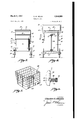
- Fig. 1 is a plan view of a preferred embodiment of my invention
- Fig. 2 is a partly sectioned side elevation corresponding to Fig. 1;
- Fig. 3 is a front view of the childs cart
- Fig. 4 is a rear View thereof with the upper portion of the handle removed;
- Fig. 5 is a perspective View of the detachable package-carrying basket.
- Fig. 6 is a fragmentary sectional view showing the locking pin forthe push handle of the device.
- the childs cart includes a body 5 having a bottom'wall 6 and a side wall I, this side wall I having a front portion 8 and a rear portion 9,
- compartment I0 the front portion 8 of the side wall I defining a childs compartment I0, and the rear portion 9 of the side wall 1 extending above the level of the upper edge of the front portion 8 and defining an accessories compartment II.
- the front portion 8 of the side wall extends around the front and along the two sides of the compartment and its height is such, for example about 10 in., that a child seated upon the floor of the compartment, formed by the bottom 6, may see out over the upper edge of the wall portion 8.
- the length and width of the childs compartment II] are of such dimension that the compartment provides ample room for the child.
- compartment Ill may be in the order of 12 in. or 14 in. wide and 18 in. to 20 in. long.
- a vertical dividing or partition wall I2 which forms the front wall of the compartment above an opening I3 between the lower edge of the wall I2 and the bottom wall 6 connecting the compartments I0 and I I.
- a seat member I3 which is of hollow construction and has a rectangular top wall I4 which constitutes the seat proper, a rear vertical wall I5 which extends from the rear edge of the top wall I4 to the bottom wall 6 and a pair of side walls I 6 which are connected to the ends of the top and rear walls I4 and I5.
- the childs compartment II] is provided with .a guard element I8 having an upper rail I9 consisting of a lightweight metal tube bent into the form of a loop as shown in Fig. 1, tubular posts .29 which extend vertically downwardly from the rail I9, and a guard strip 2
- the lower ends of the posts 20 are slidably received in the tubular parts 22 of brackets 23 which are secured to the body 5.
- the lower extremities of the posts 20 project below the brackets 23, and the posts are secured against vertical movement in the-brackets 23 by screws 24.
- the guard element I8 may be adjusted upwardly in the tubular posts 22 of the brackets 23 so as to raise the rail I9 relatively to the bottom 6 of the body 5.
- the guard element I8 is shown in Fig. 2 in its lowest position wherein the rail I9 is supported in a position near to shoulder height of a standing small infant, for example, 17 in. or 18 in.
- the guard element I8 may be raised so as to raise the level of the rail I9, removing the screws 24, sliding the posts 20 upwardly and. relatively to the brackets 23 and reinserting the screws in selected openings 25 provided in the posts 20 for this purpose.
- the body 5 is supported on rear wheels 30, rotatable upon a transverse axle 3!, and caster wheels 32 carried by caster brackets 33 which are rotatable upon the axes of substantially vertical ins 34 which project upward from the brackets 33 into supports 35 which are secured at the front corners of the body 5.
- a handle 36 is provided for the vehicle, this handle being of U- shaped. form and having side portions 31, the lower ends 38 of which are flattened for engagement of the side wall 9 of the compartment II.
- the handle is hinged on rivets 39 which extend through the upper parts of the flattened portions 38 and through the adjacent walls 9.
- the length of the side members of the handle 36 is such that the handle may be swung in forward direction from the position in which it is shown in full lines in Fig.
- the walls 9 have a number of openings 4
- the locking pins 42 are slidable in tubes 43 which are mounted in the lower ends of the side members 37 and are provided with springs 44 for urging them into projecting relation.
- Knobs 45 at the outer ends of the pins 42, may be manually engaged so as to retract the pins 42 from the openings 4
- the accessories compartment I I is equipped with a hinged cover 48, and the invention provides a supplementary luggage basket 49 which may be placed on the top of the cover 48 of the compartment II this luggage basket fitting between the side members 31 of the handle, as shown in Fig. 2, and having clips 50 for engaging the adjacent portions of the cart structure to hold the luggage basket in place on the top of the compartment I I.
- a feature of the invention resides in the provision of a brake mechanism for the cart which does not require inconvenient stooping or kneeling of the operator.
- the brake mechanism has an actuating handle 55 disposed near the upper edge of the back wall of the compartment II.
- This handle 55 is disposed at the upper end of a vertical bar or shaft 56 secured by vertically spaced bar members 5! so that it may be rotated through an angle of substantially
- a crank pin 59 connected by a link 60 to the center of a transverse flexible brake bar 6
- This brake bar 6! is connected by pivots, in the form of rivets 62 to the underside of the bottom wall 6 near the lateral extremity thereof.
- the ends 63 of the brake bar project laterally so as to lie across the tires of the rear wheels 30 of the brake bar (SI.
- the shaft may be rotated, thereby swinging the crank pin, and, through the link, pulling the central portion of the brake bar rearwardly so that the opposite halves of the brake bar will swing around the rivets and the projecting ends of the brake bar will be pulled tightly into engagement with the tires of the wheel 30, thereby locking the wheels 36 against rotation.
- the brake bar is made of spring material so that it tends to straighten when the pulling force exerted through the link is released by reverse rotation of the handle, this straightening of the brake bar causing the end portion thereof to swing away from the tires of the wheels 30, thereby releasing the braking effect.
- a childs cart of the character described the combination of a body having a bottom wall, a side wall structure extending upwardly therefrom so as to form a childs compartment, and a wall defining an accessories chamber rising above the upper edge of said side wall structure at one end of said compartment, there being a partition between said compartment and said chamber; an open work guard extending from the upper part of said accessories chamber around the upper edge of said side wall structure; supporting means secure-d in a position below said body, enabling it to be moved along a supporting surface; pivot means on the sides of the upper part of said accessories chamber; a handle swingable on said pivot means from an operative position projecting from said accessories chamber upwardly-and over said body to a retracted position at the end of said cart opposite from said accessories chamber; and lock means for retaining said handle in said operative position.
- a body having a continuous fiat bottom wall and a side wall structure extending upwardly therefrom so as to form a childs compartment, and a partition wall defining an accessories chamber, at one end of said compartment, said side wall structure being of such height that a child standing on said bottom wall cannot fall out of said compartment, the lower portion of said partition stopping at a level spaced from said bottom wall to leave a space at the lower end of said accessories chamber in communication with said compartment, said space being a continuation of said compartment into which the legs of a child reclining on said bottom wall in said compartment may be extended; wheels for said body; a seat member; means supporting said seat member in a position projecting from the lower portion of said partition wall into said compartment and so that said seat may be retracted from said position; and a handle for the operation of said cart.
- a body having a continuous flat bottom wall, a side wall structure extending upwardly therefrom so as to form a childs compartment, a wall defining an accessories chamber at one end of said compartment, and a dividing wall forming a partition between said compartment and said chamber, the lower portion of said dividing wall being spaced above said bottom wall so that there will be a space at the lower end of said accessories chamber in open communication with said compartment to receive a portion of the body of a child in said compartment; a seat; means supporting said seat in an operative position within said compartment and in a retracted position relative to said compartment when child is reclining in said compartment; supporting means secured tothe lower part of said body, enabling it to be moved along a supporting surface; and a handle means for the childs cart for use in moving it.
- a body having a continuous flat bottom wall, a side wall structure extending upwardly therefrom so as to form a childs compartment, a wall defining an accessories chamber at one end of said compartment, and a dividing wall forming a partition between said compartment and said chamber the lower portion of said dividing wall being spaced above said bottom so that there is a space at the lower end of said accessories chamber in open communication with said compartment; a seat in said compartment spaced above said bottom wall of the body at the lower portion of said partition wall, said seat having means supporting it so that the space between said seat and said bottom wall will be in open communication with said compartment; supporting means secured to said body, enabling it to be moved along a supporting surface; and a handle means for the childs cart for use in moving it.
- a body having a continuous fiat bottom wall, a side wall structure extending upwardly therefrom so as to form a childs compartment, a wall defining an accessories chamber at one end of said compartment, and a dividing wall forming a partition between said compartment and said chamber the lower portion of said dividing wall being spaced above said bottom so that there is a space at the lower end of said accessories chamber in open communication with said compartment; a seat in said compartment spaced above said bottom wall of the body at the lower portion of said partition wall, said seat having means supporting it so that the space between said seat and said bottom wall will be in open communication with said compartment, and said means supporting said seat so that it may be moved into said space at the lower end of said accessories chamber; support- REFERENCES CITED
- the following references are of record in the file of this patent:
Landscapes
- Engineering & Computer Science (AREA)
- Health & Medical Sciences (AREA)
- Public Health (AREA)
- Chemical & Material Sciences (AREA)
- Combustion & Propulsion (AREA)
- Transportation (AREA)
- Mechanical Engineering (AREA)
- Handcart (AREA)
Description
C. G. MALlN CHILDS CART March 6, 1951 2 Sheets-Sheet 1 Filed July 2, 1946 IN VENTOR fllmstez 6 mm ATTORNEY C. G. MALIN CHILDS CART March 6, 1951 2 Sheets-Sheet 2 Filed July 2, 1946 ENTQR este c G. Y BY g7 v ATTORNEY Patented Mar. 6, 11951 UNITED STATES QFFICE.
Claims. 1
My invention relates to carriages such as used for carting small children after they have passed the suckling infant age, and relates in particular to a cart for small children having a number of important features of utility whereby it is able torender especially valuable service to mothers who must take small children with them out upon the sidewalks and across streets.
There are a number of childs carts now available having a wheeled carriage portion providing a seat for the child, and a rearwardly and forwardly extending handle by which the childs vehicle is pushed along and maneuvered. These vehicles make little provision for the carrying of those accessories which must be kept handy for the care of infant children, and make no provision fOr the carrying of packages so that when the child is taken on a shopping tour the childs vehicle serves only as a means for conveniently transporting the child, but the parent or nurse is required to carry most of the packages obtained while shopping, although it is the practice to pile some of these packages in the childs vehicle.
An object of the present invention is to provide a childs cart having ample room therein in which the child is safely and conveniently carried, and also having a compartment for the carrying of accessories and/ or articles other than the accessories, such as packages and bottles space of the retracted extensible seat is a continuation of the lower portion of the childs compartment into which the feet and portions of the legs of a child in reclining position may be extended when the child is lying upon the floor of the vehicle. Accordingly, this childs cart although extensively used for conveying the child when he is awake, makes provisions whereby he may sleep, lying upon the floor of the vehicle.
A further object of the invention is to provide in this childs cart a cooperation of elements whereby the moving of the seat member from retracted to extended position accomplishes an addition to the volume of the accessories and package compartment.
A further object of the invention is to provide as a part of'the childs cart a removable basket which is detachably positioned upon the upper portion of the accessories compartment, this basket providing capacity for the transportation of a fairly large number of packages.
A further object of the invention is to provide this childs cart with a simple and effective means which must be carried home from a shopping tour.
A further object of the invention is to provide a childs cart of the general character described in the foregoing, which is of simple and economical construction, in which the child may occupy a standing, sitting or reclining position, this cart being stable so that it cannot be readily upset, and being so formed that the child cannot fall out when standing, but has unrestricted vision to the front and sides when sitting.
A further object of the invention is to provide a childs cart of this character having a chassis with a bottom and sides defining a compartment to receive the child and with a wall structure rearwardly of this compartment forming a compartment for the carrying of accessories and packages, and further to provide a hollow seat member which is slidable from the lower part of the accessories compartment into the childs compartment, thereby providing a seat for the child. The childs compartment is of such size that the child may sit either upon the floor thereof or may use the seat thus provided.
A further object of the invention is to provide in this childs cart means whereby the interior for adjusting the height of the handle and to support the handle so that it may be swung into a retracted position, thereby reducing the over all size of the cart. The adjustability of the height of the handle is of material importance. Childs carts are ordinarily made with handles of standard size and adjustment, and it is often necessary for a tall person to assume a stooping, unnatural position when wheeling such carts.
A further object of the invention is to provide a childs cart having means whereby certain dimensions of the cart may be changed as the child grows in height.
Further objects and advantages of the invention will be brought out in the following part of the specification.
Referring to the drawings, which are for illustrative purposes only:
Fig. 1 is a plan view of a preferred embodiment of my invention;
Fig. 2 is a partly sectioned side elevation corresponding to Fig. 1;
Fig. 3 is a front view of the childs cart;
Fig. 4 is a rear View thereof with the upper portion of the handle removed; and,
Fig. 5 is a perspective View of the detachable package-carrying basket. r
Fig. 6 is a fragmentary sectional view showing the locking pin forthe push handle of the device. The childs cart includes a body 5 having a bottom'wall 6 and a side wall I, this side wall I having a front portion 8 and a rear portion 9,
the front portion 8 of the side wall I defining a childs compartment I0, and the rear portion 9 of the side wall 1 extending above the level of the upper edge of the front portion 8 and defining an accessories compartment II. The front portion 8 of the side wall extends around the front and along the two sides of the compartment and its height is such, for example about 10 in., that a child seated upon the floor of the compartment, formed by the bottom 6, may see out over the upper edge of the wall portion 8. The length and width of the childs compartment II] are of such dimension that the compartment provides ample room for the child. For example, compartment Ill may be in the order of 12 in. or 14 in. wide and 18 in. to 20 in. long.
Between the upper portion of the accessories compartment II and the upper portion of the childs compartment I there is a vertical dividing or partition wall I2 which forms the front wall of the compartment above an opening I3 between the lower edge of the wall I2 and the bottom wall 6 connecting the compartments I0 and I I. In Fig. 2 I show in position retracted into the lower part of compartment H, a seat member I3 which is of hollow construction and has a rectangular top wall I4 which constitutes the seat proper, a rear vertical wall I5 which extends from the rear edge of the top wall I4 to the bottom wall 6 and a pair of side walls I 6 which are connected to the ends of the top and rear walls I4 and I5. When the seat member I3 is in the retracted position in which it is shown in full lines in Fig. 2 its interior space H constitutes an extension of the lower part of the front compartment ID. Accordingly, if the front to rear dimensions d of the seat member I3 are in the neighborhood of '7 in., the entire length of the floor or bottom wall 6 exposed when the seat member I3 is retracted, will be in the order of 25 in. to 27 in.
When the seat member I3 is in its retracted position, its top wall I4 serves as an elevated bottom for the compartment II, but when the seat member I3 is moved from retracted position to extended position I3" in the rearward part of the childs compartment I0, the rear portion of the bottom wall 6 of the body will constitute the bottom of the compartment I I, and the rear wall I5 of the seat member I3 will be positioned substantially in alignment with the dividing Wall I2.
The childs compartment II] is provided with .a guard element I8 having an upper rail I9 consisting of a lightweight metal tube bent into the form of a loop as shown in Fig. 1, tubular posts .29 which extend vertically downwardly from the rail I9, and a guard strip 2| which is secured to the posts in a position between the rail I9 and the upper edge of the side wall portion 8. The lower ends of the posts 20 are slidably received in the tubular parts 22 of brackets 23 which are secured to the body 5. The lower extremities of the posts 20 project below the brackets 23, and the posts are secured against vertical movement in the-brackets 23 by screws 24. The guard element I8 may be adjusted upwardly in the tubular posts 22 of the brackets 23 so as to raise the rail I9 relatively to the bottom 6 of the body 5. The guard element I8 is shown in Fig. 2 in its lowest position wherein the rail I9 is supported in a position near to shoulder height of a standing small infant, for example, 17 in. or 18 in. As the child grows, the guard element I8 may be raised so as to raise the level of the rail I9, removing the screws 24, sliding the posts 20 upwardly and. relatively to the brackets 23 and reinserting the screws in selected openings 25 provided in the posts 20 for this purpose.
The body 5 is supported on rear wheels 30, rotatable upon a transverse axle 3!, and caster wheels 32 carried by caster brackets 33 which are rotatable upon the axes of substantially vertical ins 34 which project upward from the brackets 33 into supports 35 which are secured at the front corners of the body 5. A handle 36 is provided for the vehicle, this handle being of U- shaped. form and having side portions 31, the lower ends 38 of which are flattened for engagement of the side wall 9 of the compartment II. The handle is hinged on rivets 39 which extend through the upper parts of the flattened portions 38 and through the adjacent walls 9. The length of the side members of the handle 36 is such that the handle may be swung in forward direction from the position in which it is shown in full lines in Fig. 2 into retracted position shown by dotted lines 36', at which time the side members of the handle lie along the sides of the body 5. Below the rivets 39 the walls 9 have a number of openings 4| disposed on arcs around the centers of the rivets 39, to receive the inner ends of adjustable locking pins 42 which are disposed in the lower ends of the side member 31. As shown in Fig. 6, the locking pins 42 are slidable in tubes 43 which are mounted in the lower ends of the side members 37 and are provided with springs 44 for urging them into projecting relation. Knobs 45, at the outer ends of the pins 42, may be manually engaged so as to retract the pins 42 from the openings 4|, thereby permitting the handle 36 to be swung through several different positions. Since the handle 36 is disposed in a sloping relation, the swinging of the handle will result in raising or lowering its upper end, to suit the requirements of the user. When the handle 36 is swung into retracted position as shown by dotted lines 36, the locking pins may engage openings 4! in the walls 9 to retain the handle in this retracted position. The accessories compartment I I is equipped with a hinged cover 48, and the invention provides a supplementary luggage basket 49 which may be placed on the top of the cover 48 of the compartment II this luggage basket fitting between the side members 31 of the handle, as shown in Fig. 2, and having clips 50 for engaging the adjacent portions of the cart structure to hold the luggage basket in place on the top of the compartment I I.
A feature of the invention resides in the provision of a brake mechanism for the cart which does not require inconvenient stooping or kneeling of the operator. The brake mechanism has an actuating handle 55 disposed near the upper edge of the back wall of the compartment II. This handle 55 is disposed at the upper end of a vertical bar or shaft 56 secured by vertically spaced bar members 5! so that it may be rotated through an angle of substantially At the lower end of the shaft 56 there is a crank pin 59 connected by a link 60 to the center of a transverse flexible brake bar 6|. This brake bar 6! is connected by pivots, in the form of rivets 62 to the underside of the bottom wall 6 near the lateral extremity thereof. The ends 63 of the brake bar project laterally so as to lie across the tires of the rear wheels 30 of the brake bar (SI. By means of the handle the shaft may be rotated, thereby swinging the crank pin, and, through the link, pulling the central portion of the brake bar rearwardly so that the opposite halves of the brake bar will swing around the rivets and the projecting ends of the brake bar will be pulled tightly into engagement with the tires of the wheel 30, thereby locking the wheels 36 against rotation. The brake bar is made of spring material so that it tends to straighten when the pulling force exerted through the link is released by reverse rotation of the handle, this straightening of the brake bar causing the end portion thereof to swing away from the tires of the wheels 30, thereby releasing the braking effect.
I claim:
1. In a childs cart of the character described, the combination of a body having a bottom wall, a side wall structure extending upwardly therefrom so as to form a childs compartment, and a wall defining an accessories chamber rising above the upper edge of said side wall structure at one end of said compartment, there being a partition between said compartment and said chamber; an open work guard extending from the upper part of said accessories chamber around the upper edge of said side wall structure; supporting means secure-d in a position below said body, enabling it to be moved along a supporting surface; pivot means on the sides of the upper part of said accessories chamber; a handle swingable on said pivot means from an operative position projecting from said accessories chamber upwardly-and over said body to a retracted position at the end of said cart opposite from said accessories chamber; and lock means for retaining said handle in said operative position.
2. In a childs cart of the character described, the combination of: a body having a continuous fiat bottom wall and a side wall structure extending upwardly therefrom so as to form a childs compartment, and a partition wall defining an accessories chamber, at one end of said compartment, said side wall structure being of such height that a child standing on said bottom wall cannot fall out of said compartment, the lower portion of said partition stopping at a level spaced from said bottom wall to leave a space at the lower end of said accessories chamber in communication with said compartment, said space being a continuation of said compartment into which the legs of a child reclining on said bottom wall in said compartment may be extended; wheels for said body; a seat member; means supporting said seat member in a position projecting from the lower portion of said partition wall into said compartment and so that said seat may be retracted from said position; and a handle for the operation of said cart.
3. In a childs cart of the character described, the combination of: a body having a continuous flat bottom wall, a side wall structure extending upwardly therefrom so as to form a childs compartment, a wall defining an accessories chamber at one end of said compartment, and a dividing wall forming a partition between said compartment and said chamber, the lower portion of said dividing wall being spaced above said bottom wall so that there will be a space at the lower end of said accessories chamber in open communication with said compartment to receive a portion of the body of a child in said compartment; a seat; means supporting said seat in an operative position within said compartment and in a retracted position relative to said compartment when child is reclining in said compartment; supporting means secured tothe lower part of said body, enabling it to be moved along a supporting surface; and a handle means for the childs cart for use in moving it.
4. In a childs cart of the character described, the combination of a body having a continuous flat bottom wall, a side wall structure extending upwardly therefrom so as to form a childs compartment, a wall defining an accessories chamber at one end of said compartment, and a dividing wall forming a partition between said compartment and said chamber the lower portion of said dividing wall being spaced above said bottom so that there is a space at the lower end of said accessories chamber in open communication with said compartment; a seat in said compartment spaced above said bottom wall of the body at the lower portion of said partition wall, said seat having means supporting it so that the space between said seat and said bottom wall will be in open communication with said compartment; supporting means secured to said body, enabling it to be moved along a supporting surface; and a handle means for the childs cart for use in moving it.
5. In a childs cart of the character described, the combination of: a body having a continuous fiat bottom wall, a side wall structure extending upwardly therefrom so as to form a childs compartment, a wall defining an accessories chamber at one end of said compartment, and a dividing wall forming a partition between said compartment and said chamber the lower portion of said dividing wall being spaced above said bottom so that there is a space at the lower end of said accessories chamber in open communication with said compartment; a seat in said compartment spaced above said bottom wall of the body at the lower portion of said partition wall, said seat having means supporting it so that the space between said seat and said bottom wall will be in open communication with said compartment, and said means supporting said seat so that it may be moved into said space at the lower end of said accessories chamber; support- REFERENCES CITED The following references are of record in the file of this patent:
UNITED STATES PATENTS Number Name Date 199,097 Palmer Jan. 8, 1878 706,854 Schulze Aug. 12, 1902 1,042,193 Bowling Oct. 22, 1912 1,212,243 QHearn Jan. 16, 1917 1,460,944 Cameron July 3, 1923 1,507,955 Dann et a1. Sept. 9, 1924 1,842,159 Fleishman et a1. Jan. 19, 1932 1,861,958 Gallinant June 7, 1932 1,973,352 Michal Sept. 11, 1934 2,254,786 Snyder Sept. 2, 1941 2,303,527 Davidson Dec. 1, 1942 2,362,186 Brantz Nov. 7, 1944 FOREIGN PATENTS Number Country Date 15,262 Great Britain July 9, 1896 175,113 Great Britain Feb. 16, 1922 219,543 Great Britain July 31, 1925 719,051 France Nov. 13, 1931
Priority Applications (1)
| Application Number | Priority Date | Filing Date | Title |
|---|---|---|---|
| US680938A US2544099A (en) | 1946-07-02 | 1946-07-02 | Child's cart |
Applications Claiming Priority (1)
| Application Number | Priority Date | Filing Date | Title |
|---|---|---|---|
| US680938A US2544099A (en) | 1946-07-02 | 1946-07-02 | Child's cart |
Publications (1)
| Publication Number | Publication Date |
|---|---|
| US2544099A true US2544099A (en) | 1951-03-06 |
Family
ID=24733124
Family Applications (1)
| Application Number | Title | Priority Date | Filing Date |
|---|---|---|---|
| US680938A Expired - Lifetime US2544099A (en) | 1946-07-02 | 1946-07-02 | Child's cart |
Country Status (1)
| Country | Link |
|---|---|
| US (1) | US2544099A (en) |
Cited By (11)
| Publication number | Priority date | Publication date | Assignee | Title |
|---|---|---|---|---|
| US2607396A (en) * | 1950-08-07 | 1952-08-19 | Jr Charles B Stambaugh | Convertible baby cart and automobile seat |
| US2756505A (en) * | 1953-09-29 | 1956-07-31 | Zaleski Stella | Marking gauge |
| US2818266A (en) * | 1954-01-27 | 1957-12-31 | Charles T Cabler | Utility vehicle for facilitating garden work |
| US2988175A (en) * | 1955-09-06 | 1961-06-13 | West Louise Rhoades | Automatic brake for a wheeled vehicle |
| US3013814A (en) * | 1958-06-16 | 1961-12-19 | Donald A Becks | Side-cart attachment for bicycles |
| US3142086A (en) * | 1961-10-17 | 1964-07-28 | William M Thomas | Caster lock mechanism |
| US3743313A (en) * | 1972-02-14 | 1973-07-03 | E Koch | Lawnmower and handle therefor |
| US4763907A (en) * | 1987-04-06 | 1988-08-16 | Country Home Products, Inc. | Utility wagon |
| USD302617S (en) | 1987-03-26 | 1989-08-01 | Country Home Products, Inc. | Ultility wagon |
| USD335731S (en) | 1991-10-23 | 1993-05-18 | Allen Theodore J | Beach cart |
| US20090039608A1 (en) * | 2007-08-06 | 2009-02-12 | Xu Hong-Bin | Braking device for playard |
Citations (16)
| Publication number | Priority date | Publication date | Assignee | Title |
|---|---|---|---|---|
| US199097A (en) * | 1878-01-08 | Improvement in children s carriages | ||
| GB189615262A (en) * | 1896-07-09 | 1896-08-22 | Otto Theodor Grunrig Rienhardt | Improvements relating to Children's Carriages, Cradles, Cots, Beds, and the like. |
| US706854A (en) * | 1901-10-16 | 1902-08-12 | Carl Wilhelm Robert Schulze | Perambulator. |
| US1042193A (en) * | 1912-03-21 | 1912-10-22 | Lilian Bowling | Go-cart handle. |
| US1212243A (en) * | 1914-10-27 | 1917-01-16 | Heywood Brothers And Wakefield Company | Go-cart. |
| GB175113A (en) * | 1920-11-25 | 1922-02-16 | Arnold Stanbury | Improvements in perambulators |
| US1460944A (en) * | 1922-05-12 | 1923-07-03 | Donald A Cameron | Body for children's vehicles |
| GB219543A (en) * | 1923-10-19 | 1924-07-31 | James Lloyd And Company Ltd | Improvements in perambulators, push-chairs or the like |
| US1507955A (en) * | 1924-02-01 | 1924-09-09 | Rattan Mfg Co | Baby carriage |
| US1842159A (en) * | 1931-03-20 | 1932-01-19 | Fleishman Morris | Perambulator body |
| FR719051A (en) * | 1931-06-23 | 1932-02-01 | Vimeux Ets | Improvements to baby carriages |
| US1861958A (en) * | 1930-08-27 | 1932-06-07 | Raphael C Gallinant | Automatic stop and compensating strut for hand propelled vehicles |
| US1973352A (en) * | 1932-07-14 | 1934-09-11 | Storkline Furniture Corp | Adjustable wheel and brake mechanism for baby carriages |
| US2254786A (en) * | 1941-04-05 | 1941-09-02 | John F Snyder | Automatic safety brake for baby carriages |
| US2303527A (en) * | 1939-07-22 | 1942-12-01 | Davidson Joseph | Carriage |
| US2362186A (en) * | 1943-08-05 | 1944-11-07 | Louis P Brantz | Chair cart |
-
1946
- 1946-07-02 US US680938A patent/US2544099A/en not_active Expired - Lifetime
Patent Citations (16)
| Publication number | Priority date | Publication date | Assignee | Title |
|---|---|---|---|---|
| US199097A (en) * | 1878-01-08 | Improvement in children s carriages | ||
| GB189615262A (en) * | 1896-07-09 | 1896-08-22 | Otto Theodor Grunrig Rienhardt | Improvements relating to Children's Carriages, Cradles, Cots, Beds, and the like. |
| US706854A (en) * | 1901-10-16 | 1902-08-12 | Carl Wilhelm Robert Schulze | Perambulator. |
| US1042193A (en) * | 1912-03-21 | 1912-10-22 | Lilian Bowling | Go-cart handle. |
| US1212243A (en) * | 1914-10-27 | 1917-01-16 | Heywood Brothers And Wakefield Company | Go-cart. |
| GB175113A (en) * | 1920-11-25 | 1922-02-16 | Arnold Stanbury | Improvements in perambulators |
| US1460944A (en) * | 1922-05-12 | 1923-07-03 | Donald A Cameron | Body for children's vehicles |
| GB219543A (en) * | 1923-10-19 | 1924-07-31 | James Lloyd And Company Ltd | Improvements in perambulators, push-chairs or the like |
| US1507955A (en) * | 1924-02-01 | 1924-09-09 | Rattan Mfg Co | Baby carriage |
| US1861958A (en) * | 1930-08-27 | 1932-06-07 | Raphael C Gallinant | Automatic stop and compensating strut for hand propelled vehicles |
| US1842159A (en) * | 1931-03-20 | 1932-01-19 | Fleishman Morris | Perambulator body |
| FR719051A (en) * | 1931-06-23 | 1932-02-01 | Vimeux Ets | Improvements to baby carriages |
| US1973352A (en) * | 1932-07-14 | 1934-09-11 | Storkline Furniture Corp | Adjustable wheel and brake mechanism for baby carriages |
| US2303527A (en) * | 1939-07-22 | 1942-12-01 | Davidson Joseph | Carriage |
| US2254786A (en) * | 1941-04-05 | 1941-09-02 | John F Snyder | Automatic safety brake for baby carriages |
| US2362186A (en) * | 1943-08-05 | 1944-11-07 | Louis P Brantz | Chair cart |
Cited By (12)
| Publication number | Priority date | Publication date | Assignee | Title |
|---|---|---|---|---|
| US2607396A (en) * | 1950-08-07 | 1952-08-19 | Jr Charles B Stambaugh | Convertible baby cart and automobile seat |
| US2756505A (en) * | 1953-09-29 | 1956-07-31 | Zaleski Stella | Marking gauge |
| US2818266A (en) * | 1954-01-27 | 1957-12-31 | Charles T Cabler | Utility vehicle for facilitating garden work |
| US2988175A (en) * | 1955-09-06 | 1961-06-13 | West Louise Rhoades | Automatic brake for a wheeled vehicle |
| US3013814A (en) * | 1958-06-16 | 1961-12-19 | Donald A Becks | Side-cart attachment for bicycles |
| US3142086A (en) * | 1961-10-17 | 1964-07-28 | William M Thomas | Caster lock mechanism |
| US3743313A (en) * | 1972-02-14 | 1973-07-03 | E Koch | Lawnmower and handle therefor |
| USD302617S (en) | 1987-03-26 | 1989-08-01 | Country Home Products, Inc. | Ultility wagon |
| US4763907A (en) * | 1987-04-06 | 1988-08-16 | Country Home Products, Inc. | Utility wagon |
| USD335731S (en) | 1991-10-23 | 1993-05-18 | Allen Theodore J | Beach cart |
| US20090039608A1 (en) * | 2007-08-06 | 2009-02-12 | Xu Hong-Bin | Braking device for playard |
| US7934731B2 (en) * | 2007-08-06 | 2011-05-03 | Wonderland Nurserygoods Co., Ltd. | Braking device for playard |
Similar Documents
| Publication | Publication Date | Title |
|---|---|---|
| US8070180B2 (en) | Stroller and shopping cart | |
| US5374073A (en) | Tractive baggage handcart | |
| US4643211A (en) | Collapsible walking frame having pivotal seat | |
| US2813725A (en) | Nesting market cart with child's seat | |
| US6651994B2 (en) | Walker with movable carry basket | |
| US3689099A (en) | Baby strollers | |
| US2720911A (en) | Convertible baby stroller and child's seat for automobiles | |
| US20100072731A1 (en) | Modular Stroller | |
| US2544099A (en) | Child's cart | |
| JPH0775984B2 (en) | Stroller reclining or lodging mechanism | |
| US2805076A (en) | Child's combination stroller, car seat, bed and highchair | |
| US2181420A (en) | Folding propulsion wheel chair | |
| US6217045B1 (en) | Massage table cart | |
| EP3615399B1 (en) | Child carrier | |
| US6308981B1 (en) | Transfer lift | |
| US3891229A (en) | Travel chair | |
| USRE30867E (en) | Travel chair | |
| US2482827A (en) | Baby vehicle | |
| US2621711A (en) | Laterally folding chair | |
| US2770288A (en) | Combination high chair and vehicle | |
| US2823043A (en) | Vertically adjustable footrest for folding baby stroller | |
| GB2033309A (en) | Collapsible framework for a pushchair, seat, or trolley | |
| US2649893A (en) | Child's convertible chair | |
| KR20160044190A (en) | Baby wagon | |
| US2532004A (en) | Child's vehicle and parcel carrier |