US2540896A - Telephone system with party lines - Google Patents
Telephone system with party lines Download PDFInfo
- Publication number
- US2540896A US2540896A US660080A US66008046A US2540896A US 2540896 A US2540896 A US 2540896A US 660080 A US660080 A US 660080A US 66008046 A US66008046 A US 66008046A US 2540896 A US2540896 A US 2540896A
- Authority
- US
- United States
- Prior art keywords
- relay
- contact
- ground
- circuit
- rotary switch
- Prior art date
- Legal status (The legal status is an assumption and is not a legal conclusion. Google has not performed a legal analysis and makes no representation as to the accuracy of the status listed.)
- Expired - Lifetime
Links
- 238000004804 winding Methods 0.000 description 69
- 238000004891 communication Methods 0.000 description 9
- 230000004048 modification Effects 0.000 description 5
- 238000012986 modification Methods 0.000 description 5
- 230000000694 effects Effects 0.000 description 3
- 230000000881 depressing effect Effects 0.000 description 2
- 241000125205 Anethum Species 0.000 description 1
- 206010010071 Coma Diseases 0.000 description 1
- 238000006066 Comins reaction Methods 0.000 description 1
- 101100114416 Neurospora crassa (strain ATCC 24698 / 74-OR23-1A / CBS 708.71 / DSM 1257 / FGSC 987) con-10 gene Proteins 0.000 description 1
- 102220347590 c.71C>T Human genes 0.000 description 1
- 230000000994 depressogenic effect Effects 0.000 description 1
- 239000001177 diphosphate Substances 0.000 description 1
- 230000005284 excitation Effects 0.000 description 1
- 230000006870 function Effects 0.000 description 1
- AKPLHCDWDRPJGD-UHFFFAOYSA-N nordazepam Chemical compound C12=CC(Cl)=CC=C2NC(=O)CN=C1C1=CC=CC=C1 AKPLHCDWDRPJGD-UHFFFAOYSA-N 0.000 description 1
- 102200096163 rs10485183 Human genes 0.000 description 1
- 102200051957 rs2472553 Human genes 0.000 description 1
Images


Classifications
-
- H—ELECTRICITY
- H04—ELECTRIC COMMUNICATION TECHNIQUE
- H04Q—SELECTING
- H04Q5/00—Selecting arrangements wherein two or more subscriber stations are connected by the same line to the exchange
Definitions
- This invention relates in general to telephone systems using partylines.
- the connected subscribers on a party line before using the line should ascertain Whether the line is free or busy, by either a visible signal or an audible signal.
- Certain systems utilize for the operation of the switching members an individual battery at each subscriber s station.
- the present invention is characterized by the registration of a call' either by the operation of a relay having mechanical engagement actuated bythe'subscribers magneto or by a control member controlled manually with mechanical engagement, such as a manual change over switch or manually operated key.
- the present invention permits getting rid of these inconveniences, that is to say, that each subscriber's station on a party line, initiates his call without preliminary checking up, and awaits his connection, while, for the purpose of economy and surety, the operation of the station no longer requires an individual battery at each station.
- the present invention is further characterized by a circuit arrangement which permits the operation of an individual selector for each station, the-stopping of this selector on the calling station, and the calling of the calling station, and also the establishment of communication with another subscribers station ontheparty line, withoututilizing a looal voltagesource, as a battery.
- Fig. I shows the equipment of'each. subscribers stationonthe party. line;
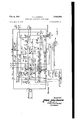
- Fig. 2. shows the; equipment ofsthe party lines connected to a manual exchange orpanel at: the
- Fig. 3 showsthe equipment of, the party lines connected to a: rural; automatic exchange; and
- Fig. 4 shows a modification of Fig. 1,,for the equipment of each subscribers station in the case in which the" call asrmade is registered by the engagement of an operating.- member controlled manually.
- the subscriber who desires to make a call rings his magneto, which causes excitation of relay 2 at the subscribers station (Fig. 1') over the circuit: the contact of the magneto, bottom contact of the switch hook; winding of rel'ay'2,
- Relay 2 having a mechanical lock remains closed If thecalling subscriber takes ofihis receiver,
- relay 2' Figs; 1 and 4
- the energization of relay 2' into operatedposi tion produces the call to the manualexc'hange over the circuit: ground, rectifier l-Stll in the direction of passage of current, contact T23- of relay 2-, rest contact of'sector a of theindividual selector, party line wireB (Fig. 2), contact C'o; upper winding of relay 32', positivebattery terminal.
- Relay 32 is held closed over the circuit, ground,
- the calling lamp is lighted overthe circuit-2 ground through the pilot relay, contactT325- of. relay 32, contact R2 23of relay 22; calling lamp, negative battery terminal.
- the combiner rotary switch X3- rotates to reach its position i by action of the circuit? ground, contact T323 of relay 3 2, contact xteo;
- X360 is the zero position or contact stud of the contact orbank e ofthe combiner X3.
- This combiner "XS-is an auxiliary rotary switch whichusually has eleven positionsnumbered from zero to ten inclusive, and its function is to complete various different combinations of contacts and The comin eleven vertical columns numbered from-zero to ten, starting from the left, so that am is-the farthest right contact in the upperright corner of. Fig. 2. These contacts are shown in the drawings as small cross-hatched squares.
- the circuit of the lamp indicatingthatwthe line is free is interrupted. at contact an.
- Relay'29 isenergizediover-the circuit: grounds contact T323 of relay 32, rest contacts of? bank Kid, contact R262 of relay 26, actuating winding of relay 29, resistance, negative battery terminal.
- Xid is the bank d of rotary switch Xi.
- Rotary switch X l is energized over the criouit through contact T294 of relay 29.
- the negative battery terminal is connected to the party line wire A over the circuit; negative battery terminal, resistance, rest contact of bani; Xia, contact 12% of relay 29, wire A (Fig. l), rectifier 592 in the direction of passage of current, Winding l or rotary switch sector b, rest contacts of rotary switch sector b, ground. Winding i is then energized.
- Fig. 4 shows the modifications in the circuit of the subscribers station of Fig. 1 when employing a member with mechanical engagement controlled manually, such as a change-over switch or manually operated key, which omits a relay.
- the party line extends from the terminals A, B,. onthe right of Fig. 1 or Fig.2, to the terminals A, B, at the central office shown in Fig. 2.
- the three lamps shown are, from top to bottom, the unoccupied lamp, the, supervision lamp, and the calling lamp.
- relay 28 is energized over the circuit: (Fig. 2) contact T222 of relay 22, and at contact T22l of relay 28 short circuits the winding of relay 2?? which opens, rotary switch Xi then advances one step, the impulse on the party line wire A is terminated, which causes all the individual selectors'to advance one step.
- Relay 22 is again energized over the circuit through ground provided by bank Xld.
- the calling unit has then been set into operation over the circuit: ground, contact al, and the waiting signal is sent by contact T326 of relay 32.
- Ihe calling machine connections are shown by five arrows in the lower right corner of Fig. 2, and these connections are multipled.
- the calling machine is put into circuit over: ground, contact a, line M, and the waiting signal is sent by line 22, condenser, T326.
- the relay 26 (Fig. 2) is held over the circuit: (Fig. 1) ground, rectifier 5223 in the direction of passage of cur-- rent, resistance 59%, contact T22 of relay 2, contacts of the sector a, line wire B (Fig. 2), contact 322i of relay 29, contact fi, contact R252 of relay 2%, upper winding of relay 22, positive battery terminal.
- relay 26 is held and at contact R252 opens the actuating circuit of relays 22 and 22.
- the relays 2 ands of the equipment of the called subscriber are energized over the circuit: negative battery terminal, resistance (Fig. 2) contact T223 of relay 26, contact fl, contact 4 R29! of relay 22, wire B (Fig. 1), contact of sector a, contact R23, windings of relays 2' and 3' in series, rectifier i906, ground.
- relay 22 (Fig. 2) isenergized over the circuit: ground, auxiliary contact of the jack, contact T22! of relay 22, winding of relay 22, negative battery terminal.
- relay 22 At its contact T222, relay 22 is held, and at its contact R223 opens the circuit of the calling lamp, rotary switch combiner X3 rotates to reach its position 2 by action of the circuit: ground, contact T22
- relay 32 (Fig. 2) is short circuited by contact 012 of the combiner and opens.
- the relays 2 and 3' (Fig. 1') are held over the circuit: negative battery terminal, resistance, contact 02, line wire B. 1
- the rectifier placed between ground and T22 permits the pasj age of the current, when on the rest position of the individual selector, the wire B is connected to a relay tied to positive battery (case of the calling of a subscribers station)
- a relay tied to positive battery case of the calling of a subscribers station
- negative battery is placed on wire B, in the rest position of the selector.
- the relay 3 is energized through the rectifier connected tothe midpoint of the relays 3 and 3.
- the rectifier placed between ground and T22 permits the passage of the current at the time of the rotation of the selector, the wire B being connected to a relay tied to positive battery. This relay becomes energized when the selector finds itself on the position of a station being called. 7 r e
- the relay I is energized by apositive battery impulse on line wire B, the return being effected through the rectifier in the sense of passing of current, the Wire A and ground.
- the relays 2' and 3' cannot become energized, the rectifier connected to the midpoint of the relays 3 and 3 being then opposed to the passage of current.
- the relay 1 At the time of energization of the relays 2 and 3' by a negative battery impulse on the wire B, the relay 1 remains at rest, the rectifier in series with it being then in inverse sense.
- tact T22 the bell of the subscriber's station through a condenser, contact T2I of relay 2, line B (Fig. 2), contact C2, resistance, negative battery terminal.
- the supervisory lamp flashes, being controlled by a fast moving cam; its circuit is completed through contact T24! of relay 24.
- relay 2'! When the subscriber takes off his receiver, the relay 2'! is closed on the release of relay 3! (Fig. 2) over a circuit similar to the preceding one, the loop being provided in the subscribers station.
- the relay 3' (Fig. 1) returns to rest position, but relay 2' remains in operated position, being mechanically held, the condenser is again inserted in the line wire A.
- the continuity of the line wires is completed through contacts d3 and 03 (Fig; 2), and the operator may then speak to the subscriber.
- relay 23 is energized, and at its contacts T232 and T235 connects the supervisory relay 25 to the line wires (Fig. 2).
- the A. C. relay 24 being short circuited, opens, relay 3
- Supervision is given by relay 25. If the subscriber hangs up, relay 25 is energized over the circuit: (Fig. 1) ground, rectifier, resistance, contact R32, switch hook, contact T2! wire B (Fig. 2), lower winding of relay 25, negative battery terminal. ,az.
- the supervisory lamp is lighted over the circuit: ground, through the pilot relay (not shown), contact T252 of relay 25, contact T23! of relay 23, contact RZM of relay 24, contact of the jack, lamp, negative battery terminal.
- the pilot relay is connected to the two arrow-marked terminals immediately above XI in the lower left corner of Fig. 2.
- the winding of relay 26 is short circuited by the ground on contact a l (Fig. 2).
- rotary switch combiner X3 rotates to reach its position 5 through the circuit: ground, contact T225 of relay 22, contact R265 of relay 26, rest contacts of bank XZa, contact ed, and so on.
- X2a is the bank of rotary switch X2.
- the dialing impulses cause rotary switch X2 to advance by virtue of the circuit: ground, contact T2 of relay 2
- control ground connection onthe' actuating windings of relay'28 and relay 2c in order t'opassposition-Di) being that given by the bank b of rctary' switch X2 Relays 23 and 2e are then. controlled by the ground connection of bank XId..
- Relay 25 is held by contact T251 and at contact R262 opens the circuit which controls relays 23 and 29, thus limiting the number of impulses to the number which is registered on rotary switch X2.
- the relays 2 and 3 (Fig. 1) of the called subscribers station are energized over the circuit: (Fig. 2) negative battery terminal, resistance, contact 03, wire b (Fig. 1), contact of the sector a, contact R23 of relay 2, windings of relays 2' and 3 in series, rectifier I926, ground, relay 2 connects the subscribers station to the line at contact T22 of relay 2, and contact T2Ii" and relay 3 short circuit'the condenser of the wire A.
- Relay SI moves. controlled by the cam and over the circuit: contact T3II' of relay '3I, contact T25 1 of relay 24, contact 56, wire A, and then ringing current is sent.
- the supervisory lamp flashes, controlled by a fast acting cam, its circuit being closed at contact T24I of relay 24.
- relay 2? is held by the circuit previously referred to, rotary switch combiner X3 rotates to reach its position i, by virtue of the circuit, ground, contact TZ'II of relay 21, contact at, and so on.
- the winding of relay 23 is energized by contact (1?, and connects the winding of relay 25 to the line, and prepares the supervisory circuit.
- the relay 22 When the operator pulls out the plug, the relay 22 opens and the rotary switch combiner X3 rotates to reach its position 8 by virtue of the circuit: ground, contact R22! of relay 22, contact fl, and so on (Fig. 2).
- relay 25 is energized as before, and rotary switch combiner X3 reaches its position 9 by virtue of the circuit: ground, contact T233 of relay 23, contact T25I of relay 25, contact f8, and so on, and relays 23 and 25 open.
- Relay 233 which had opened, is again energized by contact alt, and rotary switch combiner X3 returns'into position through contact T233 of relay 23 (Fig. 2).
- negative battery has been connected to the wire B by contact Cifl and has caused the energization of the relays 3 (Fig. 1) of the stations over the circuit: negative battery through wire B, rest contact of sector a, contact T24 of relay 2, winding of relay 3, rectifier i963, ground.
- Relay 3 then causes the release of relay 2 (Fig. 1) by unlocking a mechanical device, and all the elements are freed.
- relay 22 On pulling out the plug, relay 22 opens, rotary switch combiner X3 rotates to reach its position ii by virtue of the circuit: ground, contact R22! of relay 22, contacts iii to fl, and so on.
- Relay 23 is again energized by contact a8, and when the called subscriber hangs up, the relay 25 is energized, and rotary switch combiner X3 rotates to reach its position 9 by virtue of the circuit: ground, contact T233 of relay 23, contact T25! of relay 25, contact f8. 7 7
- the operator When the operator desires to pass a call to a station on the party line, the operator plugs in, after being assured that the circuit of the lamp which indicates that the line is not busy, is closed, and the operator depresses the dialing key.
- is energized over the circuit: ground, auxiliary contact of the jack, wire 3, then wire I connected by the dialing switch, contact be, contact R32 of relay 32, winding of relay 3!, nega- V ,tive battery terminal (Fig. 2).
- Relay 3 l on being energized removes the negative battery connection at contact Rti i of the wire 2, which permits the lighting of the dial lamp, while relay 22 is energized over the circuit: ground, auxiliary contact of the jack, contact T3i2 of relay 3 i winding of relay 22, nega- At contact REizB of relay 22, the circuit of the call lamp is opened.
- Rotary switch combiner "3 then rotates to reach its position 2 by virtue of the circuit; ground, contact "522i. of relay 22, contact T255 of relay 24, contact T265 of relay 23, contact 64, and so on; e
- Relay 3! having its circuit opened at lil', be; comes deenergized, and the dial lamp is extinui'shed.
- Negative battery is connected to wire B through contact G2, which causes (Fig 1) the return to operated condition of relays 2 and 3',as above seen, while ringing current is sent through the wire A by virtue of the circuit: contact T31! of relay 3i, contact TEM of relay 24, contact 02,
- relay 3i moving controlied by a cam by contact T245 of relay 24.
- the number transmitted by the operator causes in one or more automatic offices andrural centers connected in a chain, dinferent selections permitting the reaching of the called station.
- the line wires A and B are the party line tothe subscribers stations, as
- Relay 26 is energized through contact TH and negative battery, and rotary switch combiner X3 rotates to reach its position I by virtue of the circuit: ground, contact T232 of relay 26, contact f0, contactof combiner X3, winding of cornbiner X3, negative battery terminal.
- relay 29 is energized over the circuit: negative battery terminal, resistance, winding of relay 2%), contact R2 32 of relay 23, rest contacts of bank Xl-c, contact T336 of relay 3%, contact T262 of relay 2-5, ground (-Fig. 3).
- the supplementary battery has its positive terminal connected to ground.
- the negative battery terminal is connected to wire A.
- Relay ,2] is energized through contact T232 of relay 29 and at :itscontact T2 short circuits the relay:2,9 which becomes de-energized and opens.
- the impulse of the line Wire A will have freed the individual selectors at the a: position of rest,
- relay 2-3 is again energized over the cirbank Xlc, and contact R232 of relay 23.
- wire 13 will be connected to the positive terminal of this battery by contact T23] of relay 29 at bank XII) of rotary switch X I.
- Positive terminal of the supplementary battery (its negative terminal being connected to ground by bank Xid), upper winding of relay 2.8 (Fig. .3), contact T332 of relay 35, contact ei, contact R25, wire 13 (Fig. 1)., contact of sector a in the azimuth of the station sought, contact T22 of relay 2, resistance I935, rectifier i933, round.
- Relay 28 is held by its contact TZBI and interrupts at its contact R282 the control of the relays 29 and 21 (Fig. 3)
- relay 28 prepares the circuit passing over the position I of rotary switch combiner X3.
- relay 28 opens the circuit of relay 38 which becomes Lie-energized and opens.
- the relays 2' and 3' (Fig. 1) are energized Cover the circuit: negative battery terminal, con- 10 tact T286 of relay 28, contact R332 of relay 3!], contact cl, contact R29! of relay 29, wire B, and so on.
- Relay .2 (Fig. l) connects the subscribers station to the line and thus permits the hearing of the waiting signal which is sent by the rural exchange on the line wire A if the subscriber has takenoif his receiver, the waiting signal passing by contact (1!, condenser, wire A of the party line (Fig. 1), T33, T22, the subscribers station, T2l (Fig. 3), T283, condenser, line wire 13: of the party line, toward the rural exchange.
- the rectifiers 2233, 4333, 4304, 4336, the resistance (i325, and the jacks 4331, 4302) correspond respectiveyto the elements I903, I933, i334, i336, 1325, mm, I322, of Fig. 1.
- the condenser of the wire A is short circuited, and by contact d2 a negative battery voltage is applied tothe wire B toward the subscribers stations, which causes the relays .2 and 3' of the subscribers station to be held (Fig. l) as described above, and the ringing current is sent by the rural center to the called subscriber.
- the negative battery voltage is .connected to .the wire B, and positive battery voltage is applied to the wire A.
- the polarized relay I thus comes into its negative position which causes the rotary switch combiner to advance into its position 3 by virtue of the circuit: contact T12, negative, contact 2, and so on (Fig. 3),
- relay 25 is energized. and at contacts T253 and T255 of relay 25, it connects the relay 23 to the party line wires A and B toward the subscribers stations, while relay 25 also connects the polarized relay [to the party line wire A at contact T252 of relay 25, contact 123, and the interruption of the ground at contact R25! of relay 25.
- the relay 23 is energized over the circuit: (Fig. 1) ground, rectifier, resistance, contact R32 of relay 3, hook switch, contact T2! of relay 2', line wire B (Fig. 3) contact T255 of relay 25, lower winding of relay'23, negative battery terminal.
- the relay I (Fig. 3) is disconnected from the wire A and is connected at contact T232 of relay 23 to ground, the loop thus opened lights the supervisory lamp at the rural center.
- Rotary switch combiner X3 rotates to reach its position 4 by virtue of the circuit: ground, contact TI2 positive, contact T256 of relay 26, contact T283 of relay 28, contact f3, and so on.
- relay 25 When position 4 is reached, relay 25 has opened and the winding of relay 28 is short circuited by d4.
- the brushes corresponding to the bank 2) are spaced by 90 with relation to the banks a, c, d.
- the banks a, c, d are active, but not the bank b; on the second quarter turn, the bank b alone is active.
- Rotary switch combiner X3 rotates to reach its position 5 by virtue of the circuit: ground, contact TI2 positive, contact T26! of relay 26, contact R253, rest contact of bank X20 of rotary switch X2, contact f4, and so on.
- X20 is the bank c of rotary switch X2.
- Relay 22 has its winding energized over the circuit; ground, contact TI2 positive, contact T26! of relay 26, contact b5, rest contact of bank X2a of rotary switch X2, lower winding of relay 22, negative battery terminal.
- the application of negative battery voltage is interrupted from wire A at contact T22! of relay 22, the operator's dial lamp is then lighted indicating that the circuit is ready to receive the dialing impulses.
- has its winding connected to the wire A by virtue of the circuit: (Fig. 3) ground, winding of relay 2!, contact T22! of relay'22, contact R285 of relay '28. contact a5, wire A, and then follows the dialing impulses.
- Relay 22 is held during the dialing impulses by virtue of the circuit: ne ative battery terminal, resistance, contact T224 of relay 22, the upper winding of relay 22, ground.
- Rotary switch X2 then advances by virtue of the connection to ground and contact T2II of relay 2
- the relay 2! becomes de-energized and opens, the winding 1 of relay 22 is short circuited at contact RZII of.
- relay 2? and of relay 29 is removed at contact R282 of relay 28, and relay 28 is held by its contact T28l.
- Rotary switch combiner X3 rotates toreach its position 5 by virtue of the circuit: ground, contact TI2 negative, contact T26! of relay 26, contact T283 of relay 28, contact f5, and so on (Fig. 3).
- connection to the line of the called station is effected by putting a negative battery voltage on the wire B by contact (26.
- the relay I moves into negative position, a negative battery voltage being applied on the wire B through therural center, as well as a ground on wine A.
- the ground placed by the rural center on'the line wire A permits in position 1 of the rotary switch X3 for relay I to remain in shunt on the line until the operator unplugs.
- Rotary switch combiner X3 rotates to reach it position 7 by virtue of the circuit: ground, contact TI2 negative, contact f6, and so on.
- the relay 25 remains energized, holding the relay 23 on the line.
- the relay I comes in a positive position, the relay 22 is energized over the circuit: ground, contact TI2 positive, contact R26! of relay 26, winding of relay 22, negative battery terminal.
- the relay 23 is energized as before, and rotary switch coma-scopes ibiner X3 rotates to reach its position 9 by virtue of the circuit: ground, contact T254 of relay 35, contact T23! of relay 23, contact ]3, and so on.
- the op erator passes it in usual manner, and the supervision operates as has been described above, the rotary .switch combiner 7X3: zbein'g stopped at its position 3.
- the operator desires to pass a call to a subscribers station on the party line, the operator plugs in, and on depressing the dialing key, sends a positive battery impulse. over the line 'B, the
- Relay 2.6 is energized over the circuit: ground, contact TH positive, contact be, winding of relay 26, negative battery (Fig. 3)
- relay 22 At this position I, the winding of relay 22 is energized over the. circuit: ground, contact Tit positive, contact 'l2tl of relay 26, contact bi, rest contacts of bank X2a of rotary switch X2, lower P winding .of relay 22, negative battery, and at contact R22! .of relay 22 interrupts the negative battery connectionoi wire A.
- the tester calls a subscriber as above, and then the rotary switch ccrnbiner'iiii havin arriv-edat its position 5, the tester dials the number 3.1 on dial, which causes rotary switch X2 to advance to the position of rest of sector 12 shifted through 90' with respect to the others.
- Relay 22 becomes ale-energized and opens at the end of the train of dialing impulses.
- rotary switch combiner X3 rotates to reach its position 3 by virtue of the circuit: ground, T12 positive, contact T26! of reiay '26, contact T263 of relay 25, contact it ⁇ , and so on.
- Relay 22 Upon reaching position 1, the winding of relay 28 is short circuited through ground, and contact d4, and releases. Relay 22 returns to rest position at the end of the train of dialing impulses.
- Rotary switch X2 returns to rest position by virtue of thecircuit: ground, contact be, bank (i, then ground contact 041, contact R223 of relay 22, on the contact be, then ground and bank b.
- Rotary switch combiner X3 rotates to reach its position 5 by virtue of the circuit: ground, contact TIZ positive, contact T25! of relay 26, contact R283 of relay contact Co of rotary switch X4, contact it, and so on.
- relay 24 The winding of relay 24 is energized over the circuit: ground, winding of relay 2 contact 05, contact R223 of relay 22, rest contacts of bank X2?) of rotary switch X2, contact and winding of rotary switch X2, negative battery terminal (Fig.3).
- relay 24 Upon being energized, relay 24 holds relay 25 through its contact but opens l or" wire B at contact R2 33 of relay vZ ta-rid at contacts Ti il Sid Ti'itt of relay 2 it maintains the metallic continuity of the line wires.
- the chronometric relay set in operation by contact T2 i i of relay 24 permits of making tests, during the time that it takes to close its working contact.
- the rotary switch combiner X3 rotates to reach its position ii by virtue of the circuit: ground, contact TZM of relay 24, contact of the chronometric relay, contact T245 of relay 24, contact 95, and so on.
- relay 24 The energizing circuit of relay 24 is interrupted at contact c5, and relay 24 becomes de-energized and opens, being followed by relay 26.
- Rotary switch combiner X3 rotates to reach its position 8 by virtue of the circuit: ground, contact R262 of relay 26, contacts at and g7, and
- the rotary switch X2 passes the position of rest ofthe sector bZJi (as shown in the lower right corner of Fig. 3) over the circuit: ground, contact e9, contact R223 of relay 22, rest contacts of bank X21) of rotary switch X2,-contact and winding of rotary switch X2,
- Rotary switch X2 returns to its rest position through the sector 12.
- the position 9 is passed by: ground, rest contacts of bank Xlb of rotary switchXl, contact f9, and so on.
- a party line telephone system a central exchange; a subscribers station; a line comprising a first and a second wire for connecting said exchange to said station; in said station: a switch comprising an actuating electro-magnet, a first and a second row of contact studs, a first brush and a second brush capable of simultanecusly hunting over said two rows respectively, each of said two rows comprising a homing position, the homing position of said second row being grounded and the other contact studs of said second row being strapped; a connection between said first brush and said second wire; a connection between said second brush and said first wire through the winding of said electromagnet and a rectifying cell; a connection between the homing contact stud of said first row of contact studs and a ground through a rectifying cell and a make contact; means for closing said contact and holding it in closed position; in said central exchange: a starting relay whose winding is connected at one end to said second wire and at its other end to a battery terminal and
- a party line telephone system in which said subscribers station comprises: a connection between one contact stud of said first row of terminals and a ground through a resistance, a rectifying cell and a contact which is closed at the same time as said first mentioned contact; a connection relay, one of the two members of a back contact of said connection relay mounted in said connection, a connection between the other member 'of said back contact and a ground through the winding of said connection relay and a rectifyingrcell; said central exchange comprises battery-reversing means; said two rectifying cells'being'so oriented as to allow the passage of current therethrough after said battery-reversing means have been operated.
- connection relay comprises contacts for connecting said two wires to the subscribers receiver when said contacts are in front position.
- a party line telephone system a central exchange; a subscribers station; a line comprising a first and a second wire for connecting said exchange to said station; in said station: a switch comprising an actuating electro-magnet, a first and a second row of contact studs, a first brush and a second brush capable of simultaneously hunting over said two rows respectively, each of said two rows comprising a homingposition, the homing position of said second rowbeing grounded, and the other contact studs of said second row being strapped; a; connection between said first brush and said second wire; a connection between said second brush and said first wire through the.
- connection relay comprising two contacts for connecting said two wires to the subscribers receiver when said two contacts are in front position and said rectifying cell being so oriented as to allow the passage of current therethrough.
Landscapes
- Engineering & Computer Science (AREA)
- Computer Networks & Wireless Communication (AREA)
- Interface Circuits In Exchanges (AREA)
Description
Feb. 6, 1951 H. L. LESIGNE 2,540,896
TELEPHONE SYSTEM WITH PARTY LINES Filed April 6, 1946 3 Sheets-Sheet 2 Near/E450 Fl GU RE 2 MUU'lPllD llvwwrale fiewm tons team/v:
Feb. 6, 1951 1 s1 N 2,540,896
TELEPHONE SYSTEM WITH PARTY LINES Filed .April 6, 1946 3 Sheets-Sheet 3 FIGURE 3 nboooome HENRI tows lea/6N6 Patented Feb. 6, 1951 TELEPHONE. SYSTEM WITH PARTY LINES Henri Louis- Lesigne, Vanves, France, assigno'rto Compagnie Generale dElectricite, Paris,
France, a French' corporation Application April 6, 1946, Serial N 0. 660,080 In France July 1, 1942 EClaims. 1
This invention relates in general to telephone systems using partylines.
In known systems, the connected subscribers on a party line before using the line should ascertain Whether the line is free or busy, by either a visible signal or an audible signal. Certain systems utilize for the operation of the switching members an individual battery at each subscriber s station.
The present invention is characterized by the registration of a call' either by the operation of a relay having mechanical engagement actuated bythe'subscribers magneto or by a control member controlled manually with mechanical engagement, such asa manual change over switch or manually operated key.
The present invention permits getting rid of these inconveniences, that is to say, that each subscriber's station on a party line, initiates his call without preliminary checking up, and awaits his connection, while, for the purpose of economy and surety, the operation of the station no longer requires an individual battery at each station.
The present invention is further characterized bya circuit arrangement which permits the operation of an individual selector for each station, the-stopping of this selector on the calling station, and the calling of the calling station, and also the establishment of communication with another subscribers station ontheparty line, withoututilizing a looal voltagesource, as a battery.
The present: invention is also characterized by an arrangementand'connection of the operating elementssuchthat the, particular pieces-or equipment: at each subscribers station are interchangeable and without it being necessary to effect any mechanical modification. of the parts or a change in their connections- Other featuresv will appear from. the following description and; the accompanying drawings, wherein:
Fig. I shows the equipment of'each. subscribers stationonthe party. line;
Fig. 2. shows the; equipment ofsthe party lines connected to a manual exchange orpanel at: the
central ofilce;
Fig. 3 showsthe equipment of, the party lines connected to a: rural; automatic exchange; and
Fig. 4 shows a modification of Fig. 1,,for the equipment of each subscribers station in the case in which the" call asrmade is registered by the engagement of an operating.- member controlled manually.
Considerfirstthe case of. a localcall. utilizing the equipment connected toa manual-exchange, as shown in Fig. 2.
The subscriber who desires to make a call rings his magneto, which causes excitation of relay 2 at the subscribers station (Fig. 1') over the circuit: the contact of the magneto, bottom contact of the switch hook; winding of rel'ay'2,
contact RZi, (lower contact of-relay 2 bot tom contact of switch hook, magneto:
he hears the sound producedby-a buzzer at the subscribers station from which the short cir-- cuit is removed by contact R21, of relay 2' (Figs; 1 and 4) The energization of relay 2' into operatedposi tion produces the call to the manualexc'hange over the circuit: ground, rectifier l-Stll in the direction of passage of current, contact T23- of relay 2-, rest contact of'sector a of theindividual selector, party line wireB (Fig. 2), contact C'o; upper winding of relay 32', positivebattery terminal.
Relay 32 is held closed over the circuit, ground,
lower winding ofrela'y 32, contact T321 of relay 32, resistance, negative battery terminal.
The calling lamp is lighted overthe circuit-2 ground through the pilot relay, contactT325- of. relay 32, contact R2 23of relay 22; calling lamp, negative battery terminal.
The combiner rotary switch X3- rotates to reach its position i by action of the circuit? ground, contact T323 of relay 3 2, contact xteo;
contact X3, actuating winding ofrotary switch X3, negative battery terminal.
X360 is the zero position or contact stud of the contact orbank e ofthe combiner X3. This combiner "XS-is an auxiliary rotary switch whichusually has eleven positionsnumbered from zero to ten inclusive, and its function is to complete various different combinations of contacts and The comin eleven vertical columns numbered from-zero to ten, starting from the left, so that am is-the farthest right contact in the upperright corner of. Fig. 2. These contacts are shown in the drawings as small cross-hatched squares.
The circuit of the lamp indicatingthatwthe line is free is interrupted. at contact an.
Relay'29 isenergizediover-the circuit: grounds contact T323 of relay 32, rest contacts of? bank Kid, contact R262 of relay 26, actuating winding of relay 29, resistance, negative battery terminal. Xid is the bank d of rotary switch Xi.
- The four banks a, b, c, d of rotary switch Xi are shown adjacent its magnet.
Rotary switch X l is energized over the criouit through contact T294 of relay 29.
The negative battery terminal is connected to the party line wire A over the circuit; negative battery terminal, resistance, rest contact of bani; Xia, contact 12% of relay 29, wire A (Fig. l), rectifier 592 in the direction of passage of current, Winding l or rotary switch sector b, rest contacts of rotary switch sector b, ground. Winding i is then energized.
Fig. 4 shows the modifications in the circuit of the subscribers station of Fig. 1 when employing a member with mechanical engagement controlled manually, such as a change-over switch or manually operated key, which omits a relay.
The party line extends from the terminals A, B,. onthe right of Fig. 1 or Fig.2, to the terminals A, B, at the central office shown in Fig. 2.
' The wires i, 2, 2 at the top of Fig. 2, lead to the operators dial key, including its contacts and dial lamp.
In the upper right corner of Fig. 2, to the right of contact 222, the three lamps shown are, from top to bottom, the unoccupied lamp, the, supervision lamp, and the calling lamp.
, Then relay 28 is energized over the circuit: (Fig. 2) contact T222 of relay 22, and at contact T22l of relay 28 short circuits the winding of relay 2?? which opens, rotary switch Xi then advances one step, the impulse on the party line wire A is terminated, which causes all the individual selectors'to advance one step.
-Throu gh the circuit: contact T22i, contact T2 22a positive battery connection, and a ground, are connected respectively, to the wires B and A upon each'impulse, which causes all the individual selectors to advance, the windings I (Fig. 1) being then looped on the line.
The calling unit has then been set into operation over the circuit: ground, contact al, and the waiting signal is sent by contact T326 of relay 32.
Ihe calling machine connections are shown by five arrows in the lower right corner of Fig. 2, and these connections are multipled. The calling machine is put into circuit over: ground, contact a, line M, and the waiting signal is sent by line 22, condenser, T326.
When the selector of the calling subscribers station reaches the azimuth corresponding to the number of the subscribers station, the relay 26 (Fig. 2) is held over the circuit: (Fig. 1) ground, rectifier 5223 in the direction of passage of cur-- rent, resistance 59%, contact T22 of relay 2, contacts of the sector a, line wire B (Fig. 2), contact 322i of relay 29, contact fi, contact R252 of relay 2%, upper winding of relay 22, positive battery terminal.
At contact T265, relay 26 is held and at contact R252 opens the actuating circuit of relays 22 and 22.
-Through contact T266 of relay 22 and the contact dl, the relay 2% is energized and is then held by contact T222 of relay 24.
The relays 2 ands of the equipment of the called subscriber are energized over the circuit: negative battery terminal, resistance (Fig. 2) contact T223 of relay 26, contact fl, contact 4 R29! of relay 22, wire B (Fig. 1), contact of sector a, contact R23, windings of relays 2' and 3' in series, rectifier i906, ground.
Through contacts T2l, T22 (Fig. 1) the connection of the subscribers station to the line wires is completed over the circuit: through contact T3i', the relay 3' holds relays 2 and 3'; through contact T33, the condenser of the wire A is short circuited, relay 2' has brought relay 2 to rest by a locking mechanical device, and is held, being mechanically engaged and locked.
If the subscriber has taken ofi his receiver, he then hears the waiting signal.
When the operator plugs in, relay 22 (Fig. 2) isenergized over the circuit: ground, auxiliary contact of the jack, contact T22! of relay 22, winding of relay 22, negative battery terminal. At its contact T222, relay 22 is held, and at its contact R223 opens the circuit of the calling lamp, rotary switch combiner X3 rotates to reach its position 2 by action of the circuit: ground, contact T22| of relay 22, contact T248 of relay 22, contact T254' of relay 2%, contact cl, contact of combiner XS, actuating winding of combiner X3, negative battery terminal.
The actuating winding of relay 32 (Fig. 2) is short circuited by contact 012 of the combiner and opens. The relays 2 and 3' (Fig. 1') are held over the circuit: negative battery terminal, resistance, contact 02, line wire B. 1
At the subscribers station (Fig. 1), the rectifier placed between ground and T22 permits the pasj age of the current, when on the rest position of the individual selector, the wire B is connected to a relay tied to positive battery (case of the calling of a subscribers station) At the end of the communication, negative battery is placed on wire B, in the rest position of the selector. The preceding rectifier opposes itself to the passage of the current, the relay 3 is energized through the rectifier connected tothe midpoint of the relays 3 and 3. a
The rectifier placed between ground and T22 permits the passage of the current at the time of the rotation of the selector, the wire B being connected to a relay tied to positive battery. This relay becomes energized when the selector finds itself on the position of a station being called. 7 r e The rectifier connected to the midpoint of the relays 3 and 3, being in the'inverse sense,'is opposed to the current in the position of circuit;
ground, rectifier, relay 3', relay 2', R23.
When the negative battery is placed on the line wire B, the role of the two preceding rectifiers is changed. The first rectifier opposes the passage of current, the second rectifier permits relays 2 and 2 to become energized. I
During the advance of the individual selector, the relay I is energized by apositive battery impulse on line wire B, the return being effected through the rectifier in the sense of passing of current, the Wire A and ground. The relays 2' and 3' cannot become energized, the rectifier connected to the midpoint of the relays 3 and 3 being then opposed to the passage of current.
At the time of energization of the relays 2 and 3' by a negative battery impulse on the wire B, the relay 1 remains at rest, the rectifier in series with it being then in inverse sense.
If the calling subscriber has hung up, calling current is sent by the following operation: (Fig. 2) relay 3! moves, being'controlled by a cam, through contact TSI, contact T242 of relay 24, contact b2, wire A (Fig. 1), contact T33,'con
tact T22, the bell of the subscriber's station through a condenser, contact T2I of relay 2, line B (Fig. 2), contact C2, resistance, negative battery terminal.
The supervisory lamp flashes, being controlled by a fast moving cam; its circuit is completed through contact T24! of relay 24.
When the subscriber takes off his receiver, the relay 2'! is closed on the release of relay 3! (Fig. 2) over a circuit similar to the preceding one, the loop being provided in the subscribers station.
Throughground, contact T2'II of relay 2'! (Fig. 2), contact e2, the combiner X3 rotates to reach its position 3.
The relay 3' (Fig. 1) returns to rest position, but relay 2' remains in operated position, being mechanically held, the condenser is again inserted in the line wire A. The continuity of the line wires is completed through contacts d3 and 03 (Fig; 2), and the operator may then speak to the subscriber.
Through ground and contact :13, relay 23 is energized, and at its contacts T232 and T235 connects the supervisory relay 25 to the line wires (Fig. 2). Through ground contact (13, the A. C. relay 24 being short circuited, opens, relay 3| is interrupted by the cam at contact T242 of relay 24. Supervision is given by relay 25. If the subscriber hangs up, relay 25 is energized over the circuit: (Fig. 1) ground, rectifier, resistance, contact R32, switch hook, contact T2! wire B (Fig. 2), lower winding of relay 25, negative battery terminal. ,az.
The supervisory lamp is lighted over the circuit: ground, through the pilot relay (not shown), contact T252 of relay 25, contact T23! of relay 23, contact RZM of relay 24, contact of the jack, lamp, negative battery terminal. The pilot relay is connected to the two arrow-marked terminals immediately above XI in the lower left corner of Fig. 2.
When the operator depresses the key of the dialing device, the ground of the auxiliary contact of the jack is connected to the wire I (3 and I- being connected together) and by the contact d3 causes combiner X3 to advance to its position 4.
The winding of relay 26 is short circuited by the ground on contact a l (Fig. 2).
By release of relay 26, the actuating circuits of the two relays 28 and 28 is re-established. Rotary' switch XI comes to rest as well as all the individual selectors.
Through G the rotary switch also returns to its rest position it it is not already there.
When relay 25 and rotary switch X2 have returned to their rest positions, the rotary switch combiner X3 rotates to reach its position 5 through the circuit: ground, contact T225 of relay 22, contact R265 of relay 26, rest contacts of bank XZa, contact ed, and so on. X2a is the bank of rotary switch X2.
In position 5, the ground of wire 5 energizes relay 3| by he and contact R324. At contact R3I I, the negative battery on the wire 2 is removed, which permits the dial lamp to light.
At contact T3II' of relay 3I', the winding of relay 2 I is connected to the dial switch and follows the dialing impulses (Fig. 2).
The dialing impulses cause rotary switch X2 to advance by virtue of the circuit: ground, contact T2 of relay 2|, winding of rotary switch X2, negative battery terminal.
If the rotary switch XI has had time to return to rest position, it commences to rotate again, the
control ground connection onthe' actuating windings of relay'28 and relay 2c in order t'opassposition-Di) being that given by the bank b of rctary' switch X2 Relays 23 and 2e are then. controlled by the ground connection of bank XId..
Impulses are then sent through the line and cause the individual selectors to turn.
When rotary switch XI reache an azimuth corresponding to that which rotary switch X2 has assumed after reception of the dialing impulses, the relay 26 is closed over the circuit: negative battery terminal, resistance, bank X2a, bank Xia, contact R322 of relay 32, contact C5, lower winding of relay 26.
The operator then liftsthe dialkey,relays 3I' and 2! open. When the calling key is depressed, the relay Ed is held by the tip of the plug, wire A, contact (15, contact RSZIS of relay 3i, winding of relay 2 3, wire B, sleeve of the plug, and is held by its lower winding. Rotary switch combiner X3 rotates to reach its position 6 by virtue of the circuit: (Fig. 2) ground, contact T22I, of relay 22, contact T246 of relay 24, contact Tree of relay 26, contact c251, and so on.
The relays 2 and 3 (Fig. 1) of the called subscribers station are energized over the circuit: (Fig. 2) negative battery terminal, resistance, contact 03, wire b (Fig. 1), contact of the sector a, contact R23 of relay 2, windings of relays 2' and 3 in series, rectifier I926, ground, relay 2 connects the subscribers station to the line at contact T22 of relay 2, and contact T2Ii" and relay 3 short circuit'the condenser of the wire A.
Relay SI (Fig. 2) moves. controlled by the cam and over the circuit: contact T3II' of relay '3I, contact T25 1 of relay 24, contact 56, wire A, and then ringing current is sent.
The supervisory lamp flashes, controlled by a fast acting cam, its circuit being closed at contact T24I of relay 24.
When the called subscriber takes off his receiver, relay 2? is held by the circuit previously referred to, rotary switch combiner X3 rotates to reach its position i, by virtue of the circuit, ground, contact TZ'II of relay 21, contact at, and so on.
At Bi and Cl, the continuity of the line wires is completed.
By contact bl, the winding of relay 24 is short circuited and the relay opened.
The winding of relay 23 is energized by contact (1?, and connects the winding of relay 25 to the line, and prepares the supervisory circuit.
When the operator pulls out the plug, the relay 22 opens and the rotary switch combiner X3 rotates to reach its position 8 by virtue of the circuit: ground, contact R22! of relay 22, contact fl, and so on (Fig. 2).
Communication is then established.
If one of the subscribers then hangs up, relay 25 is energized as before, and rotary switch combiner X3 reaches its position 9 by virtue of the circuit: ground, contact T233 of relay 23, contact T25I of relay 25, contact f8, and so on, and relays 23 and 25 open.
At position 9, the relay 26 is short circuited by contact a9 and opens, and relays 28 and 29 move and cause the return to rest of the individual selectors and of rotary switch XI. Rotary switch X2 returns to rest through C9.
When rotary switch X! has returned to rest position, the rotary switch combiner X3 rotates to reach its position I!) by virtue of the circuit: ground, rest contacts of bank Xlc, contact f3, and so on.
If the communication desired is not a local communication, the operator will pass it, as usual,
' and supervision occurs as before, the rotary switch combiner X3 being at position 3 (Fig. 2).
On pulling out the plug, relay 22 opens, rotary switch combiner X3 rotates to reach its position ii by virtue of the circuit: ground, contact R22! of relay 22, contacts iii to fl, and so on.
At the position 9, the rotary switch X! the rotary switch X2 return to rest position, as well as the individual selectors, as seen above, and at position it, a releasing impulse is sent through the wire B.
When the operator desires to pass a call to a station on the party line, the operator plugs in, after being assured that the circuit of the lamp which indicates that the line is not busy, is closed, and the operator depresses the dialing key.
' Relay 3 l on being energized removes the negative battery connection at contact Rti i of the wire 2, which permits the lighting of the dial lamp, while relay 22 is energized over the circuit: ground, auxiliary contact of the jack, contact T3i2 of relay 3 i winding of relay 22, nega- At contact REizB of relay 22, the circuit of the call lamp is opened.
The dialing of the number has taken place as above explained. It is stopped by the energization of relay ZBover a circuit similar to the precedin one'which causes the operation of relay 2 by virtue of the circuit: negative battery terminal, resi tance, contact of relay 26, contact dl, lower winding of relay 2t, ground. The relay Ztis held by contact T2 i2 of relay 24 (Fig.
Rotary switch combiner "3 then rotates to reach its position 2 by virtue of the circuit; ground, contact "522i. of relay 22, contact T255 of relay 24, contact T265 of relay 23, contact 64, and so on; e
and
Through contact at, then contact oi, the ringing machine is set into operation.
Negative battery is connected to wire B through contact G2, which causes (Fig 1) the return to operated condition of relays 2 and 3',as above seen, while ringing current is sent through the wire A by virtue of the circuit: contact T31! of relay 3i, contact TEM of relay 24, contact 02,
relay 3i moving controlied by a cam by contact T245 of relay 24.
The operator observes the return of the:call
through contact T244, condenser, contact T243 The release and the return to rest position of the various elements then takes place as ex plained above. a
Referring to Fig. 3, there will now be conside-red the case Where the communication utilizes equipment controlled by a rural automatic exiiiiange. A singl supplementary battery is necessary, its terminal connected to ground being either the positive terminal or the negative terminal, according to the particular circumstances. V V a The two wires shown on the right margin of Fig, 3, are the trunk line extending to a remote automatic exchange or to another remote rural center. In some rural automatic exchanges, the subscribers stations are supplied by a local battery. The'transmissicn of dialing impulses is efiected by the operator of the center to which the calling subscriber is connected;
The number transmitted by the operator causes in one or more automatic offices andrural centers connected in a chain, dinferent selections permitting the reaching of the called station.
connected to a rural automatic exchange, which equipment is placed in a rural center. On the,
left side of this figure, the line wires A and B are the party line tothe subscribers stations, as
A, B, to an automatic exchange or to another distant rural center. 7 v
In the rural center where there is placed the equipment 'of Fig. 3, an operator can take the party line by the jack of the line P. i 7
contact 120, contact R264 of relay 26, upper winding of relay 38, positive battery terminal. The negative pole of the battery is connected to ground over the circuit: ground, contact an, rest contacts of bank Xlb, and negative battery terminal. Kid is the bank of the rotary switch Xi. Relay 3%) is held over the circuit; ground, con- 7 Fig. 3 shows the equipment of a party line,
.cuit: ground,
:tact T335 of relay 33, contact R28! of relay 28,
lower winding of relay 3!], resistance, negative tery terminal of the rural central exchange is appliedto the wire A, producing a call to the rural automatic exchange (Fig. 3).
When the distributor of the rural center has concluded its operation, a negative battery voltage is applied to the :wire B which causes it to energize in the negative position the polarized relay 1 (Fig. 3) connected to ground by contact R25! .of relay 25.
Relay 26 is energized through contact TH and negative battery, and rotary switch combiner X3 rotates to reach its position I by virtue of the circuit: ground, contact T232 of relay 26, contact f0, contactof combiner X3, winding of cornbiner X3, negative battery terminal.
Then, relay 29 is energized over the circuit: negative battery terminal, resistance, winding of relay 2%), contact R2 32 of relay 23, rest contacts of bank Xl-c, contact T336 of relay 3%, contact T262 of relay 2-5, ground (-Fig. 3).
Through contact cl, the supplementary battery has its positive terminal connected to ground. By contact T233 of relay 29, the negative battery terminal is connected to wire A.
Relay ,2] is energized through contact T232 of relay 29 and at :itscontact T2 short circuits the relay:2,9 which becomes de-energized and opens. The impulse of the line Wire A will have freed the individual selectors at the a: position of rest,
.while rotary switch XI advances by one step,
Then relay 2-3 is again energized over the cirbank Xlc, and contact R232 of relay 23.
Through bank Xld of rotary switch XI, the negative terminal of the supplementary battery at the manual central office is connected to ground, the next impulse willapply the negative voltage of "the supplementary battery ,(i. e.
ground) to wire A, while wire 13 will be connected to the positive terminal of this battery by contact T23] of relay 29 at bank XII) of rotary switch X I.
The stopping on the calling subscriber will take place by energization of relay 2.3 over the following circuit:
Positive terminal of the supplementary battery (its negative terminal being connected to ground by bank Xid), upper winding of relay 2.8 (Fig. .3), contact T332 of relay 35, contact ei, contact R25, wire 13 (Fig. 1)., contact of sector a in the azimuth of the station sought, contact T22 of relay 2, resistance I935, rectifier i933, round.
At contact T283, relay 28 prepares the circuit passing over the position I of rotary switch combiner X3.
At its contact T284, relay 28 completes the continuity of wire 33.
At its contact R231 relay 28 opens the circuit of relay 38 which becomes Lie-energized and opens.
The negative battery voltage on the wire A towards the automatic exchange is out 01f at contact R235 of relay28.
The relays 2' and 3' (Fig. 1) are energized Cover the circuit: negative battery terminal, con- 10 tact T286 of relay 28, contact R332 of relay 3!], contact cl, contact R29! of relay 29, wire B, and so on.
Relay .2 (Fig. l) connects the subscribers station to the line and thus permits the hearing of the waiting signal which is sent by the rural exchange on the line wire A if the subscriber has takenoif his receiver, the waiting signal passing by contact (1!, condenser, wire A of the party line (Fig. 1), T33, T22, the subscribers station, T2l (Fig. 3), T283, condenser, line wire 13: of the party line, toward the rural exchange.
In the arrangement shown in Fig. 4, for the equipment of each subscribers station. in the case in which the call is registered by the engagement of -a member controlled manually, the rectifiers 2233, 4333, 4304, 4336, the resistance (i325, and the jacks 4331, 4302, correspond respectiveyto the elements I903, I933, i334, i336, 1325, mm, I322, of Fig. 1.
When the operator of the rural manual center plugs in, a positive battery voltage is applied on the wire B which brings the relay I into the positive position. Relay .26, which is retarded, remains held by contact Tl l, positive, and contact T253 of relay .26 (Fig. 3).
Through the circuit: ground, contact Tl2 positive, contact T26! of relay .26, contact T283 of relay 2-8, contact fl, and so on, the rotary switch combiner X3 rotates to reach its position 2.
At contact 012, the condenser of the wire A is short circuited, and by contact d2 a negative battery voltage is applied tothe wire B toward the subscribers stations, which causes the relays .2 and 3' of the subscribers station to be held (Fig. l) as described above, and the ringing current is sent by the rural center to the called subscriber.
When the calledsubscriber answers, providing the loop, the negative battery voltage applied to Wire B by the contact.cl2 through the loop of the subscriberis station, energizesthe relay stopping the call of the rural center.
The negative battery voltage is .connected to .the wire B, and positive battery voltage is applied to the wire A.
The polarized relay I thus comes into its negative position which causes the rotary switch combiner to advance into its position 3 by virtue of the circuit: contact T12, negative, contact 2, and so on (Fig. 3),
,At contacts 113 and (13 the continuity of the line wires is completed.
Through contact 03, relay 25 is energized. and at contacts T253 and T255 of relay 25, it connects the relay 23 to the party line wires A and B toward the subscribers stations, while relay 25 also connects the polarized relay [to the party line wire A at contact T252 of relay 25, contact 123, and the interruption of the ground at contact R25! of relay 25.
In case the subscriber hangs up, the relay 23 is energized over the circuit: (Fig. 1) ground, rectifier, resistance, contact R32 of relay 3, hook switch, contact T2! of relay 2', line wire B (Fig. 3) contact T255 of relay 25, lower winding of relay'23, negative battery terminal.
At contact R232 of relay 23, the relay I (Fig. 3) is disconnected from the wire A and is connected at contact T232 of relay 23 to ground, the loop thus opened lights the supervisory lamp at the rural center.
Assume that local communication'is to be handled. By depressing the dial key, the operator 7 i1 sends a negative battery voltage over the line B, relay I comes into the positive position.
Rotary switch combiner X3 rotates to reach its position 4 by virtue of the circuit: ground, contact TI2 positive, contact T256 of relay 26, contact T283 of relay 28, contact f3, and so on.
When position 4 is reached, relay 25 has opened and the winding of relay 28 is short circuited by d4.
Through contact a4, a negative battery voltage is sent over the wire A, preventing the dial lamp from lighting. The circuit for return to the rest position of the rotary switch X2 is closed through: ground, contact b2, bank X20! of rotary switch X2, contact of rotary switch X2, actuating winding of rotary switch X2, negative battery terminal, then ground, contact e2, contact R223 of relay 22, rest contact of bank X21), of rotary switch X2, the contact and actuating winding of rotary switch X2, negative battery terminal, then ground, and bank X21) of rotary switch X2 (Fig. 3).
The actuating circuit of relays 2! and 29 being again completed at contact R282 of relay 28, im-
' pulses are sent toward thesubscribers stations,
thus causing the individual selectors to return to rest position, as well as rotary switch XI.
For the rotary switch X2, the brushes corresponding to the bank 2) are spaced by 90 with relation to the banks a, c, d.
Thus, on the first, quarter turn, the banks a, c, d, are active, but not the bank b; on the second quarter turn, the bank b alone is active.
Rotary switch combiner X3 rotates to reach its position 5 by virtue of the circuit: ground, contact TI2 positive, contact T26! of relay 26, contact R253, rest contact of bank X20 of rotary switch X2, contact f4, and so on. X20 is the bank c of rotary switch X2.
If rotary switch X! has rotated to reach its rest position, it then leaves its rest position, and relays 2'! and 29 are controlled over the circuit: ground, contact T252 of relay 26, bank X2c of rotary switch X2, rest contacts of bank Xlc of rotary switch XI, contact R282 of relay 28, and so on. The ground control is that of bank Xlc of rotary switch XI (Fig. 3).
Impulses are then sent toward the subscribers stations as has been described above.
At the end of the train of impulses, the relay 2! becomes de-energized and opens, the winding 1 of relay 22 is short circuited at contact RZII of.
relay '2! and also opens.
When rotary switch XI has rotated to; reach the azimuth corresponding to the number which has been dialed and sent, the winding of relay 28 is energized over the circuit: ground, lower winding of relay 28, contact d5, contact R304 of relay 30, bank Xla of rotary switch XI, bank X2a of rotary switch X2, resistance, negative battery terminal. r
The control of relay 2? and of relay 29 is removed at contact R282 of relay 28, and relay 28 is held by its contact T28l.
Rotary switch combiner X3 rotates toreach its position 5 by virtue of the circuit: ground, contact TI2 negative, contact T26! of relay 26, contact T283 of relay 28, contact f5, and so on (Fig. 3). I 7
After having dialed, the operatorlifts the dial key and depresses the calling key, the effect of which is to send a positive battery impulse over the wire; BI thus remains in positive position, and alternating current over the wire A is sent by the automatic exchange.
On the other hand, the connection to the line of the called station is effected by putting a negative battery voltage on the wire B by contact (26.
By contact as (shown at the top of Fig.3 in the sixth vertical column from the left), the condenser of the wire A is short circuited. The stopping of the calling, on answering, is madein the same manner as above explained.
The relay I moves into negative position, a negative battery voltage being applied on the wire B through therural center, as well as a ground on wine A. The ground placed by the rural center on'the line wire A permits in position 1 of the rotary switch X3 for relay I to remain in shunt on the line until the operator unplugs.
Rotary switch combiner X3 rotates to reach it position 7 by virtue of the circuit: ground, contact TI2 negative, contact f6, and so on.
At contacts a! and til, the continuity of the talking circuit is completed.
Through contact 0! of the combiner, the winding'of relay25 is energized and the winding of relay 23 is connected to the wires A and B at contacts T253 and T255 of relay 25 (Fig. 3).
Through contact T252 of relay 25, contact b1, the winding of relay I is connected to the wire A, while at contact T25! of relay 25, it is cut off from the local ground (Fig. 3)
Supervision takes place in a manner similar to that previously described.
When a local communication is being handled, the operator pulls out the plug, then relay 26 opens, and rotary switch combiner X3 rotates to reach its position 8 by virtue of the circuit: ground, contact R262 of relay 26, contact g1, and so on.
Through contact C3, the relay 25 remains energized, holding the relay 23 on the line.
Through contact a8,'relay I is connected to ground, thus permitting its energization by the circuit from the automatic exchange.
Local communication is thus established.
If the operator wishes to pass another call, the relay I comes in a positive position, the relay 22 is energized over the circuit: ground, contact TI2 positive, contact R26! of relay 26, winding of relay 22, negative battery terminal.
Through contact T222 of relay 22, contact R255 of relay 26, a negative battery voltage is applied to the wire A and signals to the operator when the line is busy (Fig. 3).
If a subscriber hangs up his receiver, the relay 23 is energized as before, and rotary switch coma-scopes ibiner X3 rotates to reach its position 9 by virtue of the circuit: ground, contact T254 of relay 35, contact T23! of relay 23, contact ]3, and so on.
If the local call is interrupted by a timin or 'chronometric relay, the triple negative :connec 'tion is established. This :chronometric relay cpcrates over the circuit: ground, contact T256 of "relay 25, contact T25! of relay 25, Contact contact of the chronometric relay, winding, nega tive battery. When the contact of the chrono- If the operation is such that the local call is notzto be interrupted at the endof a definite time,
the triple positive connection is made.
When the operator located at the test table of the rural center wishes to interrupt the call, the s operator moves relay I into negative position and then :into positive position. Relay 26 is then energized-and is held, the chronometric relay is put intocircuit through: ground, contact Ti-2 positive,
contact T26! of relay 26, contact 298, contact and windingoi the .chronometric relay, negative battery.
When the operator has closed the working contact, the rotary switch combiner X3 reaches :position 9, and the call is interrupted.
At this position -9, the winding of relay 28 is short circuited by the contact all), and in opening, the'relay '28 re-establishes a circuit of the relays '21 and 29 which move, and cause rotary switch Xi and the individual selectors to wine to rest.
Through contact 129, bank XZd, the rotary switch X2 comes to rest.
When rotary switch XI has rotated to reach the rest position, the rotary switch combiner X3 rotates to reach its position It by virtue of the circuit: ground, rest contacts of bank Xlb of rotary switch XI, contact f9, and soon (Fig. 3).
In the position I 0, a negative battery voltage is sent over the wire B towards the subscribers stations by contact dill, and thus produces, as above described, the release of the members belonging to thesubscribers stations.
Through contact c'HJ, the winding of relay 25 is energized, and by vi-rtueof the circuit: ground, contactT254 of relay 25, contact fI-ll, and so on, causes rotaryswitch combiner Xi? toadvance to its position El. All the parts are then freed.
If the call requested is not a local call, the op erator passes it in usual manner, and the supervision operates as has been described above, the rotary .switch combiner 7X3: zbein'g stopped at its position 3.
When the plug is pulled out, the :relay l and the relay 26 are de-energized and opened, and the rotary switch combiner X3 rotates to reach its position 8 by Virtue of the circuit: ground, contact R262 of relay 26, contacts 93 to Q1, and
ISO .011.
At position 8, thewwinding of relay 25.115 energizedand the position 8 is freed over the circuit: ground, contact T254 of relay 2.5, contact T23! of relay 23, contact f8, the winding of relay 23 being energized when a subscriber has hung up his receiver.
Upon reaching position 9, the rotary switches come to rest in the same manner as has been above described, and upon reaching position Iii, release takes place.
If the operator desires to pass a call to a subscribers station on the party line, the operator plugs in, and on depressing the dialing key, sends a positive battery impulse. over the line 'B, the
:effect of which is to cause relay to come into the positive position. Relay 2.6 is energized over the circuit: ground, contact TH positive, contact be, winding of relay 26, negative battery (Fig. 3)
'Rotary switch combiner X3 rotates to reach its position .I by virtue of the circuit: ground,
contact T2132 of relay 2.5,.ccntact f0, and so on.
At this position I, the winding of relay 22 is energized over the. circuit: ground, contact Tit positive, contact 'l2tl of relay 26, contact bi, rest contacts of bank X2a of rotary switch X2, lower P winding .of relay 22, negative battery, and at contact R22! .of relay 22 interrupts the negative battery connectionoi wire A.
Through contacts of relay '22 and R235 of relay 23, contact a], the winding of relay 2| is connected to .the wireA and follows the dialing impulses. These dialing impulses are produced as above explained.
The sending of the dialing impulses to the stations, and the stopping, are effected as before described. The winding of relay is then energized through contact all. The succession of operating steps is identical with that above described.
If the tester wishes to make tests, the tester calls a subscriber as above, and then the rotary switch ccrnbiner'iiii havin arriv-edat its position 5, the tester dials the number 3.1 on dial, which causes rotary switch X2 to advance to the position of rest of sector 12 shifted through 90' with respect to the others. Relay 22 becomes ale-energized and opens at the end of the train of dialing impulses.
To describe the operation in more detail, the
rotary switch combiner X3 rotates to reach its position 3 by virtue of the circuit: ground, T12 positive, contact T26! of reiay '26, contact T263 of relay 25, contact it}, and so on.
Upon reaching position 1, the winding of relay 28 is short circuited through ground, and contact d4, and releases. Relay 22 returns to rest position at the end of the train of dialing impulses.
Rotary switch X2 returns to rest position by virtue of thecircuit: ground, contact be, bank (i, then ground contact 041, contact R223 of relay 22, on the contact be, then ground and bank b.
Rotary switch combiner X3 rotates to reach its position 5 by virtue of the circuit: ground, contact TIZ positive, contact T25! of relay 26, contact R283 of relay contact Co of rotary switch X4, contact it, and so on.
The winding of relay 24 is energized over the circuit: ground, winding of relay 2 contact 05, contact R223 of relay 22, rest contacts of bank X2?) of rotary switch X2, contact and winding of rotary switch X2, negative battery terminal (Fig.3).
Upon being energized, relay 24 holds relay 25 through its contact but opens l or" wire B at contact R2 33 of relay vZ ta-rid at contacts Ti il Sid Ti'itt of relay 2 it maintains the metallic continuity of the line wires.
The chronometric relay set in operation by contact T2 i i of relay 24 permits of making tests, during the time that it takes to close its working contact. When the working contact is established, the rotary switch combiner X3 rotates to reach its position ii by virtue of the circuit: ground, contact TZM of relay 24, contact of the chronometric relay, contact T245 of relay 24, contact 95, and so on.
15 The energizing circuit of relay 24 is interrupted at contact c5, and relay 24 becomes de-energized and opens, being followed by relay 26.
Rotary switch combiner X3 rotates to reach its position 8 by virtue of the circuit: ground, contact R262 of relay 26, contacts at and g7, and
so on (Fig.3).
When the subscriber hangs up his receiver, the position 8 is passed, the relay 25 is energized, and the receiver having been hung up, relay 23 is operated over the circuit: ground, contact T254 of relay 25, contact T23! of relay 23, contact f8, and so on.
At position 9, the rotary switch X2 passes the position of rest ofthe sector bZJi (as shown in the lower right corner of Fig. 3) over the circuit: ground, contact e9, contact R223 of relay 22, rest contacts of bank X21) of rotary switch X2,-contact and winding of rotary switch X2,
negative battery. Rotary switch X2 returns to its rest position through the sector 12.
The position 9 is passed by: ground, rest contacts of bank Xlb of rotary switchXl, contact f9, and so on.
The sending of the negative wire impulse over the wire B producing the release of the subscribers station and the passage from the position it], takes place as has been above described.
The embodiments which have been above described, have been given by way of example, and certain parts described, or groups of parts, could be replaced by other elements giving the same result, or all such elements or parts of them could be combined with difierent embodiments without departing from the scope of the present 7 invention.
It will be apparent to those skilled in the art that my invention is susceptible of modifications to adapt the same to particular operating conditions, and all such modifications which are within the scope of the appended claims I consider to be comprehended within the spirit of my invention. 1
I claim:
1. In a party line telephone system: a central exchange; a subscribers station; a line comprising a first and a second wire for connecting said exchange to said station; in said station: a switch comprising an actuating electro-magnet, a first and a second row of contact studs, a first brush and a second brush capable of simultanecusly hunting over said two rows respectively, each of said two rows comprising a homing position, the homing position of said second row being grounded and the other contact studs of said second row being strapped; a connection between said first brush and said second wire; a connection between said second brush and said first wire through the winding of said electromagnet and a rectifying cell; a connection between the homing contact stud of said first row of contact studs and a ground through a rectifying cell and a make contact; means for closing said contact and holding it in closed position; in said central exchange: a starting relay whose winding is connected at one end to said second wire and at its other end to a battery terminal and means operated by said starting relay for applying the other battery terminal to said first wire; both cells being so oriented as to allow the passage of current therethrough.
2. A party line telephone system according to claim 1 in which said subscribers station comprises: a connection between one contact stud of said first row of terminals and a ground through a resistance, a rectifying cell and a contact which is closed at the same time as said first mentioned contact; a connection relay, one of the two members of a back contact of said connection relay mounted in said connection, a connection between the other member 'of said back contact and a ground through the winding of said connection relay and a rectifyingrcell; said central exchange comprises battery-reversing means; said two rectifying cells'being'so oriented as to allow the passage of current therethrough after said battery-reversing means have been operated.
3. A party line telephone system according to claim 2, in which said connection relay comprises contacts for connecting said two wires to the subscribers receiver when said contacts are in front position.
4. A party line telephone system according to claim 2, in which the operation of said connection relay causes the opening of said contact first mentioned in claim 1.'
5. In a party line telephone system: a central exchange; a subscribers station; a line comprising a first and a second wire for connecting said exchange to said station; in said station: a switch comprising an actuating electro-magnet, a first and a second row of contact studs, a first brush and a second brush capable of simultaneously hunting over said two rows respectively, each of said two rows comprising a homingposition, the homing position of said second rowbeing grounded, and the other contact studs of said second row being strapped; a; connection between said first brush and said second wire; a connection between said second brush and said first wire through the. winding of said electro-magnet and a rectifying cell; a connection between a contact stud or" said first row and a ground through a connection relay, 2. back contact of said relay and a rectifying cell, said connection relay comprising two contacts for connecting said two wires to the subscribers receiver when said two contacts are in front position and said rectifying cell being so oriented as to allow the passage of current therethrough.
HENRI LOUIS LESIGNE.
REFERENGES CITED The following references are of record in the file of this patent: V
UNITED STATES PATENTS Number Name Date 984,204 Erickson Feb. 14, 1911 1,000,077 Cummings et a1. Aug. 8, 1911 1,067,274 Richey July 15, 1913 1,206,761 Hastings Nov. 28, 1916 1,457,338 Burrows et a1. June 5, 1923 1,896,315 Kapp Feb. 7, 1933 2,013,354 Lomax Sept. 3, 1935 Certificate of Correction Patent No. 2,540,896 February 6, 1951 HENRI LOUIS LESIGNE It is hereby certified that error appears in the above numbered patent requiring correction as follows:
In the grant, line 14, strike out or SEVENTEEN YEARS; same line, after GRANT insert until July 1, 1.962; and in the heading to the printed specification, between line 7 and line 8, insert the following: Section 1, Public Law 690, August 8, 1946. Patent ewpires July 1, 1.962;
and that the said Letters Patent should be read as corrected above, so that the same may conform to the record of the case in the Patent Office.
This certificate supersedes Certificate of Correction issued June 26, 1951. Signed and sealed this 11th day of September, A. D. 1951.
[SEAL] THOMAS F. MURPHY,
Assistant Commissioner of Patents.
Applications Claiming Priority (1)
| Application Number | Priority Date | Filing Date | Title |
|---|---|---|---|
| FR2540896X | 1942-07-01 |
Publications (1)
| Publication Number | Publication Date |
|---|---|
| US2540896A true US2540896A (en) | 1951-02-06 |
Family
ID=9686298
Family Applications (1)
| Application Number | Title | Priority Date | Filing Date |
|---|---|---|---|
| US660080A Expired - Lifetime US2540896A (en) | 1942-07-01 | 1946-04-06 | Telephone system with party lines |
Country Status (1)
| Country | Link |
|---|---|
| US (1) | US2540896A (en) |
Citations (7)
| Publication number | Priority date | Publication date | Assignee | Title |
|---|---|---|---|---|
| US984204A (en) * | 1906-04-16 | 1911-02-14 | First Trust & Savings Bank | Lock-out for party-line-telephone subscribers' stations. |
| US1000077A (en) * | 1909-03-03 | 1911-08-08 | George C Cummings | Transmission system. |
| US1067274A (en) * | 1912-11-06 | 1913-07-15 | Phone Call Recorder Company | Telephone register and lock-out device. |
| US1206761A (en) * | 1913-08-20 | 1916-11-28 | Internat Telephone Co | Telephone systems. |
| US1457338A (en) * | 1919-04-01 | 1923-06-05 | American Telephone & Telegraph | Selective connection of trunk lines |
| US1896315A (en) * | 1932-03-25 | 1933-02-07 | Associated Electric Lab Inc | Telephone system |
| US2013354A (en) * | 1933-07-13 | 1935-09-03 | Associated Electric Lab Inc | Intercommunicating telephone and signaling system |
-
1946
- 1946-04-06 US US660080A patent/US2540896A/en not_active Expired - Lifetime
Patent Citations (7)
| Publication number | Priority date | Publication date | Assignee | Title |
|---|---|---|---|---|
| US984204A (en) * | 1906-04-16 | 1911-02-14 | First Trust & Savings Bank | Lock-out for party-line-telephone subscribers' stations. |
| US1000077A (en) * | 1909-03-03 | 1911-08-08 | George C Cummings | Transmission system. |
| US1067274A (en) * | 1912-11-06 | 1913-07-15 | Phone Call Recorder Company | Telephone register and lock-out device. |
| US1206761A (en) * | 1913-08-20 | 1916-11-28 | Internat Telephone Co | Telephone systems. |
| US1457338A (en) * | 1919-04-01 | 1923-06-05 | American Telephone & Telegraph | Selective connection of trunk lines |
| US1896315A (en) * | 1932-03-25 | 1933-02-07 | Associated Electric Lab Inc | Telephone system |
| US2013354A (en) * | 1933-07-13 | 1935-09-03 | Associated Electric Lab Inc | Intercommunicating telephone and signaling system |
Similar Documents
| Publication | Publication Date | Title |
|---|---|---|
| US2369868A (en) | Telephone system | |
| US2540896A (en) | Telephone system with party lines | |
| US1647796A (en) | Telephone system | |
| US2867690A (en) | Auxiliary sender circuit | |
| US1859924A (en) | Call charging telephone exchange system | |
| US2271878A (en) | Telephone system | |
| US2447494A (en) | Telephone register control system | |
| US2921987A (en) | Two-way trunk circuit | |
| US2338752A (en) | Telephone system | |
| US2289503A (en) | Telephone system | |
| US1979020A (en) | Telephone exchange system | |
| US2427000A (en) | Coin-operated telephone system | |
| US2033283A (en) | Signaling system | |
| US2184844A (en) | Telephone system | |
| US1881273A (en) | Telephone system | |
| US1907240A (en) | Service observing equipment | |
| US1893691A (en) | Multioffice telephone system | |
| US2311774A (en) | Telephone system | |
| US2433359A (en) | Multirural semiautomatic telephone exchange system | |
| US2225305A (en) | Telephone system | |
| US1866593A (en) | Call distributing system | |
| US1855779A (en) | Telephone system | |
| US1848196A (en) | Semiautomatic rural telephone system | |
| US2105898A (en) | Telephone exchange system | |
| US3123674A (en) | jdsti |