US2540640A - Electron discharge device system for obtaining similar or differential tuning adjustments - Google Patents
Electron discharge device system for obtaining similar or differential tuning adjustments Download PDFInfo
- Publication number
- US2540640A US2540640A US733076A US73307647A US2540640A US 2540640 A US2540640 A US 2540640A US 733076 A US733076 A US 733076A US 73307647 A US73307647 A US 73307647A US 2540640 A US2540640 A US 2540640A
- Authority
- US
- United States
- Prior art keywords
- motors
- switch
- pair
- motor
- terminals
- Prior art date
- Legal status (The legal status is an assumption and is not a legal conclusion. Google has not performed a legal analysis and makes no representation as to the accuracy of the status listed.)
- Expired - Lifetime
Links
- 239000004020 conductor Substances 0.000 description 23
- 230000002441 reversible effect Effects 0.000 description 22
- 230000008878 coupling Effects 0.000 description 10
- 238000010168 coupling process Methods 0.000 description 10
- 238000005859 coupling reaction Methods 0.000 description 10
- 239000003990 capacitor Substances 0.000 description 6
- 230000005540 biological transmission Effects 0.000 description 4
- 230000007935 neutral effect Effects 0.000 description 2
- 240000008042 Zea mays Species 0.000 description 1
- 235000005824 Zea mays ssp. parviglumis Nutrition 0.000 description 1
- 235000002017 Zea mays subsp mays Nutrition 0.000 description 1
- 235000005822 corn Nutrition 0.000 description 1
- 238000010438 heat treatment Methods 0.000 description 1
- 230000001939 inductive effect Effects 0.000 description 1
- 238000007689 inspection Methods 0.000 description 1
- 238000000034 method Methods 0.000 description 1
- 238000004804 winding Methods 0.000 description 1
Images

Classifications
-
- H—ELECTRICITY
- H03—ELECTRONIC CIRCUITRY
- H03F—AMPLIFIERS
- H03F3/00—Amplifiers with only discharge tubes or only semiconductor devices as amplifying elements
- H03F3/20—Power amplifiers, e.g. Class B amplifiers, Class C amplifiers
- H03F3/22—Power amplifiers, e.g. Class B amplifiers, Class C amplifiers with tubes only
-
- H—ELECTRICITY
- H03—ELECTRONIC CIRCUITRY
- H03J—TUNING RESONANT CIRCUITS; SELECTING RESONANT CIRCUITS
- H03J3/00—Continuous tuning
-
- H—ELECTRICITY
- H03—ELECTRONIC CIRCUITRY
- H03J—TUNING RESONANT CIRCUITS; SELECTING RESONANT CIRCUITS
- H03J3/00—Continuous tuning
- H03J3/02—Details
- H03J3/12—Electrically-operated arrangements for indicating correct tuning
Definitions
- This invention relates broadly to an arrangement for simultaneously obtaining similar or dif- I ferential tuning adjustments of a pair of adjustable elements in an electron discharge device system.
- An object of the present invention is to provide individual reversible motors for the controls of an electron discharge device system and by means of a switching arrangement, enable any pair of these controls to operate similarly to the same degree either in the same or opposite directions, and thus facilitate the adjustment of the system.
- Another object is to provide a means for readily compensating for dissimilarities in the two line branches of the input or output circuits of paralleled vacuum tube amplifiers, whereby it becomes practical to use branching circuits of definitely dissimilar characteristics.
- a further object is to provide a technique of obtaining similar or differential tuning adjustments which will simplify the tuning of paralleled amplifiers at high frequencies.
- a feature of the invention lies in the switching arrangement for a plurality of pairs of reversible motors, whereby a single switch used for all pairs of motors acts as a reversing switch for reversing the direction of rotation of one motor in each pair relative to the direction of rotation of the other motor in the same pair.
- Fig. 1 illustrates, schematically, a pair of vacuum tube amplifier stages coupled together in electrically parallel relation, and having adjustable elements individually controlled by reversible motors in accordance with the principles of the invention, whereby correspondingly positioned controls can be simultaneously operated in the same or opposite directions;
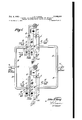
- Fig. 2 illustrates, schematically, an electrical switching arrangement for controlling the pairs of reversible motors shown in Fig. 1;
- Fig. 2a schematically illustrates the electrical circuit of a capacitor-reversing type of motor which can be used in the invention.
- Fig. l there are shown a pair of triode vacuum tube amplifier stages I and I coupled together in electrically parallel relation.
- Amplifier I has its grid and anode connected to the outer and inner conductors 3 and 4, respectively, of a concentric line tank circuit.
- the filament of amplifier I is fed by a pair of heater wires 6 extending through the interior of a metallic tubular conductor 1 in such manner that wires 6 and tubular conductor 1 form a resonant cathode line.
- the outer conductors of resonant cathode line 6, l and output line 3, 4 are grounded, although it should be observed that the cathode line is grounded at a voltage nodal point.
- Heating supply for the filament is fed to conductors B through a filament transformer, not shown, connected to wires 6 at the end of the cathode line farthest removed from the vacuum tube l.
- Anode polarizing potential is fed to inner conductor 3 through choke coil 8.
- Condensers Cl, C2 and C3 are radio frequency bypass capacitors. It will thus be noted that the grid of tube l is grounded for radio frequency energy.
- the cathode line 6, l is resonated to the operating frequency by means of a variable capacitor 9 which is controlled by a reversible motor l0 through a shaft II.
- the anode tank line 3, 4 is tuned by means of a traveling slider or short-circuiting bar containing a built-in capacitor l2, and the position of this slider is controlled by a reversible motor l3 through a shaft [4.
- the high frequency input signal is supplied to the cathode circuit 6, l of amplifier stage I by means of a variable coupling loop l5which is magnetically coupled to the outer conductor 3 'l.
- the inner conductors B of the cathode line vary in radio frequency potential with the outer conductor l.
- Input loop l5 has its couplin to the cathode line varied and controlled by a reversible motor it through a shaft ii.
- variable coupling loop iii which is located in the interior of anode line 3, 4.
- the degree of coupling of loop is to line 3, 4 is controlled by reversible motor is through shaft 26.
- Amplifier stage i is arranged similarly to amplifier I, and because the correspondingly positioned circuit elements of stage i operate and are arranged similarly to those of stage 6 they have been given the same reference characters except for the prime designations.
- the paralleled amplifiers l and l are fed with input waves through branches or sections of transmission line 33, 30 from a common feed point 32, in turn, coupled to a line TL extending to a suitable source of input waves, for example the output tank circuit of a preceding stage.
- the driver or input voltage supplied to line TL divides approximately equally into both branches 3t and 39 and is conveyed to the two input coupling loops l5 and i5.
- the output coupling loops l3 and i8 feed their respective outputs through branches or sections of transmission line Si, St to a common junction point and then to a single common line TL extending to a suitable load, such as an antenna.
- Each of the reversible motors is preferably of the capacitor-reversing type to which alternating current is supplied at any one time over only two of the three leads shown associated with each motor.
- Those motors which drive correspondingly located adjustable elements in the two amplifier stages rotate at approximately the same speed.
- the pair of motors it and iii which drive variable capacitors 9 and 9' respec tively, operate at the same speed, and the pair of motors iii and it which vary the inductive coupling of input loops l5 and i5, respectively, relative to their associated cathode lines, also operate at the same speed, and so on.
- Fig. 2 shows the switching arrangement used to control only two pairs of reversible motors it, Hi and it, Iii, although it should be understood that as many pairs of motors as desired may be added to this arrangement, and be similarly controlled.
- the motors are the same as those shown in the system of Fig. 1 and have been given the same reference characters.
- motors in and iii comprise one pair and control correspondingly positioned cathode tuning capacitors .9 and Q.
- Motors l5 and 55 comprise another pair and control correspondingly positioned input coupling loops l5 and iii.
- pairs of motors l9, l9 and l3, l3 may be and are preferably added to Fig. 2
- Each motor is of the capacitor-reversing type, as shown in Fig. 2a, and includes a pair of stator windings 5G and El, a rotor 52, and three terminals lilii, HM and W2. A capacitor connected across terminals itl and M2.
- the motor is adapted to be energized by alternating current.
- the application of A. C. power to terminals E03 and H32 will cause the motor to rotate in one direction, while the application of this same A. C. power to terminals i6 3 and HM will cause the motor to rotate in an opposite direction.
- Switch St has three positions; namely, an upper closed position designated A, a lower closed position desi nated B, and a middle or neutral position in which the switch is unoperated and the knife blades do not engage any contacts.
- One side of the A. C. supply is connected to both blades of switch S5, while the other side 53 of the A. 0. supply is connected to the terminals ifit of all. of the motors.
- Switch S5 has both of its blades directly connected together by a wire connection 68.
- the upper and lower center and right contacts of the switch S are directly connected together in criss-cross manner as shown and connected to the upper and lower right contacts of switch S5 by connections El and 62.
- the terminals liii and 162 of motor it] are connected through leads 5% and 5 respectively to the upper and lower
- the terminals M35 and $62 of motor it are connected through leads 53 and '59 to the right and middle blades of switch S4.
- the pairs of motors I6 and I6 are connected to the same power supply through lead 53 and switch S6.
- the terminals I60 of motors I6 and I6 are directly connected together.
- the terminals IOI and I02 of both motors I6 and I6 are connected to switch S6 in the same manner as the corresponding terminals of motors I and I0 are connected to switch S4.
- the lower middle and right contacts of switch S6 are connected tov correspondingly positioned contacts on switch S4 through leads SI and 62.
- Motors I6 and I6 will rotate in directions like those set forth for motors I0 and II) for comparable settings of switches S6 and S5.
- Switch S5 acts as a reversing switch for the terminals IDI and I02 of one of the motors (viz.,
- the same switch S5 can be used in common for any desired plurality of pairs of motors.
- switch S5 When switch S5 is in the unoperated or middle position in which its blades do not engage any of its contacts, it prevents the operation of any of the motors of any pair.
- the invention provides a ready means available to differentially tune two halves of the parallel circuit in order to accommodate any electrical differences between the two parallel branches, so that both electron discharge devices look into equivalent circuits, and therefore operate under the same conditions.
- the operator by means of the reversing switch, and by reference to the meters indicating anode current, grid current and power output, has adjusted the two sides of the circuit to balance, the tracking over the small changes in tuning required to keep the circuits resonated, for example, when it becomes necessary to replace one of the tubes, may be accomplished by manipulation of the necessary tuning switches, with the reversal switch in the proper position to drive the motors in-phase. In efiect, therefore, it becomes possible to tune the circuits of the two branches by a common control and thereby greatly simplify the task of the operator.
- the paralleled amplifiers were RCA type power amplifier tubes in a 50 kw.
- frequency modulation transmitter operating over i a frequency range of 88 to 104 megacycles.
- An electron discharge device system including one or more multi-electrode vacuum tubes having resonant circuits and a pair of adjustable electrical tuning elements in circuit with the electrodes of said tubes for varying the tuning of said resonant circuits, 9, separate reversible motor controlling each adjustable tuning element, and switching means coupled to said motors for opcrating them simultaneously to run either in the same direction or in opposite directions relative to each other at approximately the same speed at the option of the operator, said switching means including a pair of manually operable interconnected switches.
- An electron discharge device system having a pair of multi-electrode electron tubes and a pair of similarly positioned electrical tuning controls in circuit with corresponding electrodes of said tubes, a pair of reversible motors for said controls, each motor being linked to a single tuning control, a single source of power supply for said pair of motors, and switching mechanism coupled to said motors for causing them to rotate simultaneously in the same direction or simultaneously in opposite directions relative to each other and at the same speed at the option of the operator, said switching means including a pair of manually operable interconnected switches.
- An electron discharge device system having a pair of multi-electrode electron amplifier tubes and a pair of similarly positioned adjustable electrical tuning elements in circuit with corresponding electrodes of said tubes, a separate capacitortype of reversible motor linked to each adjustable element, a common source of power suppl for said motors, and a pair of manually operable interconnected switches connected to said source and to said motors and to each other in such manner that said motors run simultaneously in the same direction or in opposite directions relative to each other depending upon the operation of said switches, one of said switches being a reversing switch for one of said motors relative to the other motor.
- An electron discharge device system having a pair of multi-electrode vacuum tube amplifiers connected in electrically parallel relation, said amplifiers having a plurality of similarly positioned controls in circuit with corresponding electrodes, a separate reversible motor linked to each of said controls, a common source of power supply for all of said motors, and switching means connected to said source and said motors for causing the motors connected to like controls to run simultaneously in the same direction or opposite directions relative to each other at the option of the operator, said switching means including a pair of manually operable interconnected switches.
- An electron discharge device system having a pair of multi-electrode vacuum tube amplifiers connected in electrically parallel relation, a radio frequency current carrying line, a pair of branch lines connected at one end to said line and coupled at their other ends to similar circuits coupled to corresponding electrodes of said amplifiers through individual adjustable coupling loops, a reversible motor linked to each coupling loop for varying the degree of magnetic coupling between the loop and the circuit in association therewith, and common switching mechanism coupled to said motors for operating said motors simultaneously in the same direction or opposite directions relative to each other at the option of the operator, said switching mechanism including a pair of manually operable multi-blade double-throw switches having interconnected contacts.
- An electron discharge device system having a pair of multi-electrode vacuum tube amplifiers connected in electrically parallel relation, said amplifiers including in circuit with corresponding electrodes tunable line-type electrical resonators eachhaving a movable tuning slider, a reversible motor' linked to each tuning slider for moving the same over a portion of the length of its associated resonator, and common switching means coupled to said reversible motors for causing them to operate simultaneously in the same direction or in opposite directions relative to each other at the option of the operator, to thereby cause said sliders to simultaneously move in the same or opposite directions over their respective resonators, said switching means including a pair of manually operable interconnected multi-blade switches.
- An electron discharge device system including a pair of multi-electrode electron tubes and a pair of similarly positioned adjustable tuning elements in circuit with the electrodes of said tubes; a separate reversible A. 0. motor linked to and controlling each adjustable element, said motors being similar, each of said motors having first, second and third terminals, a common twoconductor A. C.
- An electron discharge device system having a pair of multi-electrode electric tubes in circuit with each other, said tubes having similarly positioned adjustable electrical tuning controls in circuit with corresponding electrodes, separate reversible motors linked to said controls, a common ing mechanism including a pluralit of doublethrow multiple blade switches having interconnected contacts, and connections from said switches to said source and to said motors and to each other 'so constructed and arranged that any predetermined pair of said motors operate simultaneously in the same or opposite directions, depending upon the operated positions of said switches.
- An electron discharge device system including a pair of adjustable tuning elements for electron discharge device electrodes of said system, a separate reversible A.
- An electron discharge device system having a pair of tuning controls for electron discharge device electrodes of said system, a pair of reversible alternating current motors for said controls, each motor having three terminals, a connection between one terminal of one motor and a corresponding terminal of the other motor, individual condensers connected across the other two terminals of said motors, a pair of doublethrow multiple blade switches, connections from one of said switches to two terminals of one motor, connections from said same switch to the corresponding two terminals of the other motor, a two-conductor A.
- An electron discharge device system including one or more multi-electrode vacuum tubes having a pair of adjustable elements in circuit with the electrodes of said tubes, a separate alternating current reversible motor controlling, each adjustable element, said motors being simi lar and each having first, second and third terminals, a connection between said first terminals, a two-conductor A.
Landscapes
- Engineering & Computer Science (AREA)
- Power Engineering (AREA)
- Amplifiers (AREA)
- Control Of Position Or Direction (AREA)
Description
Feb. 6, 1951 J. E. YOUNG ELECTRON DISCHARGE DEVICE SYSTEM FOR OBTAINING SIMILAR 0R DIFFERENTIAL TUNING ADJUSTMENTS Filed March 7, 1947 2 Sheets-Sheet l lllplllllllllll l| llllllul 1 if FM Feb. 6, 1951 2,540,640
J. E. YOUNG ELE 0N DISCHA DEVICE S EM OBTAINING S LAR OR DI RENTIAL T NG USTMENTS Filed March 7, 1947 2 Sheets-Sheet 2 N VEN TOR.
Jbhz .Yazry vkgw Patented Feb. 6, 1951 ELECTRON DISCHARGE DEVICE SYSTEM FOR OBTAINING SIMILAR OR DIFFEREN- TIAL TUNING ADJUSTMENTS John Ellwood Young, Merchantville, N. J., assignor to Radio Corporation of America, a corporation of Delaware Application March 7, 1947, Serial No. 733,076
12 Claims. 1
This invention relates broadly to an arrangement for simultaneously obtaining similar or dif- I ferential tuning adjustments of a pair of adjustable elements in an electron discharge device system.
In operating a pair of vacuum tube amplifiers in parallel relation, it has been customary to feed the input electrodes of the tubes by individual sections or branches of transmission line connected to a common feed point, and to obtain outputs from the two tubes also by means of individual sections or branches of transmission line connectedto a common output point, and to make the input and output branching lines, respectively, identical in length and characteristics. In such a system, it has been customary to attempt to make the circuits associated with each amplifier tube likewise identical. Heretofore, independent controls have been provided on each of the paralleled amplifiers to perform the various tuning functions. At high frequencies, however, the desired identity of characteristics in correspondingly positioned circuits is difficult to obtain, because of the large eifect minute mechanical changes in a tuning or couplng element may have on the electrical characteristics of its associated circuit. For this reason the tuning of such paralleled amplifiers has been extremely difficult.
An object of the present invention is to provide individual reversible motors for the controls of an electron discharge device system and by means of a switching arrangement, enable any pair of these controls to operate similarly to the same degree either in the same or opposite directions, and thus facilitate the adjustment of the system.
Another object is to provide a means for readily compensating for dissimilarities in the two line branches of the input or output circuits of paralleled vacuum tube amplifiers, whereby it becomes practical to use branching circuits of definitely dissimilar characteristics.
A further object is to provide a technique of obtaining similar or differential tuning adjustments which will simplify the tuning of paralleled amplifiers at high frequencies.
A feature of the invention lies in the switching arrangement for a plurality of pairs of reversible motors, whereby a single switch used for all pairs of motors acts as a reversing switch for reversing the direction of rotation of one motor in each pair relative to the direction of rotation of the other motor in the same pair. An important advantage of the switching arrangement of the invention is that no tuning can be effected unless the reversing switch is first positioned in other than a neutral setting.
A more detailed description of the invention follows in conjunction with a drawing wherein:
Fig. 1 illustrates, schematically, a pair of vacuum tube amplifier stages coupled together in electrically parallel relation, and having adjustable elements individually controlled by reversible motors in accordance with the principles of the invention, whereby correspondingly positioned controls can be simultaneously operated in the same or opposite directions;
Fig. 2 illustrates, schematically, an electrical switching arrangement for controlling the pairs of reversible motors shown in Fig. 1; and
Fig. 2a schematically illustrates the electrical circuit of a capacitor-reversing type of motor which can be used in the invention.
Referring to Fig. l in more detail, there are shown a pair of triode vacuum tube amplifier stages I and I coupled together in electrically parallel relation.
Amplifier I has its grid and anode connected to the outer and inner conductors 3 and 4, respectively, of a concentric line tank circuit. The filament of amplifier I is fed by a pair of heater wires 6 extending through the interior of a metallic tubular conductor 1 in such manner that wires 6 and tubular conductor 1 form a resonant cathode line. The outer conductors of resonant cathode line 6, l and output line 3, 4 are grounded, although it should be observed that the cathode line is grounded at a voltage nodal point. Heating supply for the filament is fed to conductors B through a filament transformer, not shown, connected to wires 6 at the end of the cathode line farthest removed from the vacuum tube l. Anode polarizing potential is fed to inner conductor 3 through choke coil 8. Condensers Cl, C2 and C3 are radio frequency bypass capacitors. It will thus be noted that the grid of tube l is grounded for radio frequency energy.
The cathode line 6, l is resonated to the operating frequency by means of a variable capacitor 9 which is controlled by a reversible motor l0 through a shaft II. The anode tank line 3, 4 is tuned by means of a traveling slider or short-circuiting bar containing a built-in capacitor l2, and the position of this slider is controlled by a reversible motor l3 through a shaft [4.
The high frequency input signal is supplied to the cathode circuit 6, l of amplifier stage I by means of a variable coupling loop l5which is magnetically coupled to the outer conductor 3 'l. The inner conductors B of the cathode line vary in radio frequency potential with the outer conductor l. Input loop l5 has its couplin to the cathode line varied and controlled by a reversible motor it through a shaft ii.
The high frequency output from amplifier stage I is extracted by variable coupling loop iii which is located in the interior of anode line 3, 4. The degree of coupling of loop is to line 3, 4 is controlled by reversible motor is through shaft 26.
Amplifier stage i is arranged similarly to amplifier I, and because the correspondingly positioned circuit elements of stage i operate and are arranged similarly to those of stage 6 they have been given the same reference characters except for the prime designations.
The paralleled amplifiers l and l are fed with input waves through branches or sections of transmission line 33, 30 from a common feed point 32, in turn, coupled to a line TL extending to a suitable source of input waves, for example the output tank circuit of a preceding stage.
From the foregoing, it will be seen that the driver or input voltage supplied to line TL divides approximately equally into both branches 3t and 39 and is conveyed to the two input coupling loops l5 and i5.
The output coupling loops l3 and i8 feed their respective outputs through branches or sections of transmission line Si, St to a common junction point and then to a single common line TL extending to a suitable load, such as an antenna.
Each of the reversible motors is preferably of the capacitor-reversing type to which alternating current is supplied at any one time over only two of the three leads shown associated with each motor. Those motors which drive correspondingly located adjustable elements in the two amplifier stages rotate at approximately the same speed. Thus, the pair of motors it and iii which drive variable capacitors 9 and 9' respec tively, operate at the same speed, and the pair of motors iii and it which vary the inductive coupling of input loops l5 and i5, respectively, relative to their associated cathode lines, also operate at the same speed, and so on.
By means of the switching feature of the pres-'- ent invention, as will appear hereinafter in connection with the description of Fig. 2, it is proposed to energize each pair of motors which control corresponding adjusting elements in the paralleled amplifiers, by a single switch in such manner that the motors of each pair can rotate in the same or opposite directions, to thereby control corresponding adjusting or tuning elements similarly to the same degree or difieren tially. I am thus able to obtain either in-phase or differential tuning of like tuning or control elements on the two sides of the parallel circuit.
Fig. 2 shows the switching arrangement used to control only two pairs of reversible motors it, Hi and it, Iii, although it should be understood that as many pairs of motors as desired may be added to this arrangement, and be similarly controlled. The motors are the same as those shown in the system of Fig. 1 and have been given the same reference characters. Thus, motors in and iii comprise one pair and control correspondingly positioned cathode tuning capacitors .9 and Q. Motors l5 and 55 comprise another pair and control correspondingly positioned input coupling loops l5 and iii. In the same manner, pairs of motors l9, l9 and l3, l3 may be and are preferably added to Fig. 2
left contacts of switch S6.
to control correspondingly positioned adjusting elements, but are not shown in Fig. 2 inasmuch as the principles of operation are the same as for pairs of motors it, ill and i6, i6 and any additional illustration will not add to but may detract from the clarity of the drawing.
Each motor is of the capacitor-reversing type, as shown in Fig. 2a, and includes a pair of stator windings 5G and El, a rotor 52, and three terminals lilii, HM and W2. A capacitor connected across terminals itl and M2. The motor is adapted to be energized by alternating current. The application of A. C. power to terminals E03 and H32 will cause the motor to rotate in one direction, while the application of this same A. C. power to terminals i6 3 and HM will cause the motor to rotate in an opposite direction.
Referring to Fig. 2 in more detail, it will be noted that there is a single alternating current power supply line 53, for supplying 220 volts A. C. to operate the diiTerent pairs of motors it, it and l6, it. For controlling the direction of rotation of motors Iii and iii there is provided a three-blade, double-throw switch S4 and a two-blade double throw switch S5. Switch St has three positions; namely, an upper closed position designated A, a lower closed position desi nated B, and a middle or neutral position in which the switch is unoperated and the knife blades do not engage any contacts. One side of the A. C. supply is connected to both blades of switch S5, while the other side 53 of the A. 0. supply is connected to the terminals ifit of all. of the motors. Switch S5 has both of its blades directly connected together by a wire connection 68.
The upper and lower center and right contacts of the switch S are directly connected together in criss-cross manner as shown and connected to the upper and lower right contacts of switch S5 by connections El and 62. The terminals liii and 162 of motor it] are connected through leads 5% and 5 respectively to the upper and lower The terminals M35 and $62 of motor it are connected through leads 53 and '59 to the right and middle blades of switch S4.
The directions of rotation of the pair of motors i it and iii are given in the following table in which an arbitrary assumption has been made that, if voltage is applied between terminals it?) and ifll, rotation will be in a clockwise direc tion; and if voltage is applied between terminals m and 592, rotation will be in a counter-clockwise direction. The operating paths for these motors are obvious to anyone skilled in the art from a mere inspection of the drawing:
3 Position of g gg Direction Rotation Direction Rotation Switch S4 S5 Motor 10 Motor 10 A A Clockwise Clockwise.
A; Counter-clockwise.
B Do.
B Clockwise.
Unopcrated None.
from their directions 01. rotation when switch S4 is on the A position and switch S5 on the B position.
The pairs of motors I6 and I6 are connected to the same power supply through lead 53 and switch S6. The terminals I60 of motors I6 and I6 are directly connected together. The terminals IOI and I02 of both motors I6 and I6 are connected to switch S6 in the same manner as the corresponding terminals of motors I and I0 are connected to switch S4. The lower middle and right contacts of switch S6 are connected tov correspondingly positioned contacts on switch S4 through leads SI and 62.
Motors I6 and I6 will rotate in directions like those set forth for motors I0 and II) for comparable settings of switches S6 and S5.
Switch S5 acts as a reversing switch for the terminals IDI and I02 of one of the motors (viz.,
tive to the other motor of the same pair. -Hence,.
the same switch S5 can be used in common for any desired plurality of pairs of motors.
When switch S5 is in the unoperated or middle position in which its blades do not engage any of its contacts, it prevents the operation of any of the motors of any pair.
To operate additional pairs of motors it is only necessary to add an additional switch like S5 for each additional pair of motors and to connect these additional motors in a manner similar .to the connections from motors I6, I6 to the switches.
It-will thus be seen that the invention provides a ready means available to differentially tune two halves of the parallel circuit in order to accommodate any electrical differences between the two parallel branches, so that both electron discharge devices look into equivalent circuits, and therefore operate under the same conditions. Furthermore, when the operator, by means of the reversing switch, and by reference to the meters indicating anode current, grid current and power output, has adjusted the two sides of the circuit to balance, the tracking over the small changes in tuning required to keep the circuits resonated, for example, when it becomes necessary to replace one of the tubes, may be accomplished by manipulation of the necessary tuning switches, with the reversal switch in the proper position to drive the motors in-phase. In efiect, therefore, it becomes possible to tune the circuits of the two branches by a common control and thereby greatly simplify the task of the operator.
Although the invention has been described with particular reference to a pair of tubes connected in electrically parallel relation, it should be understood that the principles of the invention are equally applicable for controlling adjustments of the input and output tuning controls of a single vacuum tube circuit, such as an amplifier.
In one embodiment of the invention successfully tried out in practice, the paralleled amplifiers were RCA type power amplifier tubes in a 50 kw.
frequency modulation transmitter operating over i a frequency range of 88 to 104 megacycles.
What is claimed is:
1. An electron discharge device system including one or more multi-electrode vacuum tubes having resonant circuits and a pair of adjustable electrical tuning elements in circuit with the electrodes of said tubes for varying the tuning of said resonant circuits, 9, separate reversible motor controlling each adjustable tuning element, and switching means coupled to said motors for opcrating them simultaneously to run either in the same direction or in opposite directions relative to each other at approximately the same speed at the option of the operator, said switching means including a pair of manually operable interconnected switches.
2. An electron discharge device system having a pair of multi-electrode electron tubes and a pair of similarly positioned electrical tuning controls in circuit with corresponding electrodes of said tubes, a pair of reversible motors for said controls, each motor being linked to a single tuning control, a single source of power supply for said pair of motors, and switching mechanism coupled to said motors for causing them to rotate simultaneously in the same direction or simultaneously in opposite directions relative to each other and at the same speed at the option of the operator, said switching means including a pair of manually operable interconnected switches.
3. An electron discharge device system having a pair of multi-electrode electron amplifier tubes and a pair of similarly positioned adjustable electrical tuning elements in circuit with corresponding electrodes of said tubes, a separate capacitortype of reversible motor linked to each adjustable element, a common source of power suppl for said motors, and a pair of manually operable interconnected switches connected to said source and to said motors and to each other in such manner that said motors run simultaneously in the same direction or in opposite directions relative to each other depending upon the operation of said switches, one of said switches being a reversing switch for one of said motors relative to the other motor.
4. An electron discharge device system having a pair of multi-electrode vacuum tube amplifiers connected in electrically parallel relation, said amplifiers having a plurality of similarly positioned controls in circuit with corresponding electrodes, a separate reversible motor linked to each of said controls, a common source of power supply for all of said motors, and switching means connected to said source and said motors for causing the motors connected to like controls to run simultaneously in the same direction or opposite directions relative to each other at the option of the operator, said switching means including a pair of manually operable interconnected switches.
5. An electron discharge device system having a pair of multi-electrode vacuum tube amplifiers connected in electrically parallel relation, a radio frequency current carrying line, a pair of branch lines connected at one end to said line and coupled at their other ends to similar circuits coupled to corresponding electrodes of said amplifiers through individual adjustable coupling loops, a reversible motor linked to each coupling loop for varying the degree of magnetic coupling between the loop and the circuit in association therewith, and common switching mechanism coupled to said motors for operating said motors simultaneously in the same direction or opposite directions relative to each other at the option of the operator, said switching mechanism including a pair of manually operable multi-blade double-throw switches having interconnected contacts.
6. An electron discharge device system having a pair of multi-electrode vacuum tube amplifiers connected in electrically parallel relation, said amplifiers including in circuit with corresponding electrodes tunable line-type electrical resonators eachhaving a movable tuning slider, a reversible motor' linked to each tuning slider for moving the same over a portion of the length of its associated resonator, and common switching means coupled to said reversible motors for causing them to operate simultaneously in the same direction or in opposite directions relative to each other at the option of the operator, to thereby cause said sliders to simultaneously move in the same or opposite directions over their respective resonators, said switching means including a pair of manually operable interconnected multi-blade switches.
'7. An electron discharge device system including a pair of multi-electrode electron tubes and a pair of similarly positioned adjustable tuning elements in circuit with the electrodes of said tubes; a separate reversible A. 0. motor linked to and controlling each adjustable element, said motors being similar, each of said motors having first, second and third terminals, a common twoconductor A. C. power supply line for said motors, first and second double-throw, multiple blade switches, one of said switches having three blades and a pair of contacts on opposite sides of each blade, connections between the second and third terminals of one motor and the outer contacts associated with one outer blade of said threeblade switch and cross-connections between the other contacts associated with the other two blades of said three-blade switch, a connection between said one outer blade and a pair of similarly positioned outer contacts on one side of said other switch, connections between said other con-- tacts of the three-blade switch and the other outer contacts on the other side of the other switch, a connection between the first terminal of one motor and a corresponding terminal of the other motor and to one conductor of said power line, separate connections from the second and third terminals of the other motor to the other two blades of said three-blade switch, and a connection from the other conductor of said power line to the outer blades of said other switch. 1
8. An electron discharge device system having said controls, each motor having three terminals,
a connection between one terminal of one motor and a corresponding terminal of the other motor, individual condensers connected across the other two terminals of said motors, a pair of doublethrow multiple blade switches, connections from one of said switches to two terminals of one motor, connections from said same switch to the corresponding two terminals of the other motor, a two-conductor A. C. power sup-ply line, a connection from one conductor of said line to the third terminal of both motors, and a connection from the other conductor of said line to said other switch, and connections between the corn tacts of one of said switches and between said switches so arranged that said motors run simultaneously only when both of said switches are operated and one switch acts as a reversing switch for one motor relative to the other motor.
9. An electron discharge device system having a pair of multi-electrode electric tubes in circuit with each other, said tubes having similarly positioned adjustable electrical tuning controls in circuit with corresponding electrodes, separate reversible motors linked to said controls, a common ing mechanism including a pluralit of doublethrow multiple blade switches having interconnected contacts, and connections from said switches to said source and to said motors and to each other 'so constructed and arranged that any predetermined pair of said motors operate simultaneously in the same or opposite directions, depending upon the operated positions of said switches.
10. An electron discharge device system including a pair of adjustable tuning elements for electron discharge device electrodes of said system, a separate reversible A. C. motor linked to and con" trolling each adjustable element, said motors being similar, each of said motors having first, second and third terminals, a common two-conductor A. 0. power supply line for said motors, first and second double-throw, multiple blade switches, one of said switches having three blades and three contacts in the same straight line for association with each blade, connections between the second and third terminals of one motor and the outer contacts associated with one outer blade of said three-blade switch and cross-connections between the other outer contacts associated with the other two blades of said three-blade switch, a connection between said one outer blade and a pair of similarly positioned contacts on one side of said other switch, connections between said other outer contacts of the three-blade switch and the other contacts on the other side of the other switch, a connection between the first terminal of one motor and a corresponding terminal of the other motor and to one conductor of said power line, separate connections from the second and third terminals of the other motor to the other two blades of said three-blade switch, and a connection from the other conductor of said power line to the blades of said other switch.
- 11. An electron discharge device system having a pair of tuning controls for electron discharge device electrodes of said system, a pair of reversible alternating current motors for said controls, each motor having three terminals, a connection between one terminal of one motor and a corresponding terminal of the other motor, individual condensers connected across the other two terminals of said motors, a pair of doublethrow multiple blade switches, connections from one of said switches to two terminals of one motor, connections from said same switch to the corresponding two terminals of the other motor, a two-conductor A. C. power supply line, a connection from one conductor of said line to the third terminal of both motors and which third terminal corresponds to said aforementioned one terminal, and a connection from the other conductor of said line to said other switch, and connections between the contacts of one of said switches and between said switches so arranged that said motors run simultaneously only when both of said switches are operated and one switch sets as a reversing switch for one motor relative to the other motor.
12. An electron discharge device system including one or more multi-electrode vacuum tubes having a pair of adjustable elements in circuit with the electrodes of said tubes, a separate alternating current reversible motor controlling, each adjustable element, said motors being simi lar and each having first, second and third terminals, a connection between said first terminals, a two-conductor A. C. power lin for said motors, a connection from one conductor of said power source of power supply for said motors, switchline to said first terminals, a double-throw multiblade switch having contacts connected to the second and third terminals of one of said motors and blades connected to the second and third terminals of said other motor, another double-throw multi-blade switch having blades connected to the other conductor of said power line and contacts connected to the contacts of said first switch, one of said switches acting as a reversing switch for one of said motors relative to the other motor.
JOHN ELLWOOD YOUNG.
REFERENCES CITED The following references are of record in the file of this patent:
Number '10 UNITED STATES PATENTS Name Date Jones Aug. 14, 1934 Hansell Oct. 19, 1937 Adams Sept. 10, 1940 Peterson June 10, 1941 Higgins Feb. 9, 1943 Cunningham et a1. May 22, 1945 Ginzton Sept. 10, 1946
Priority Applications (2)
| Application Number | Priority Date | Filing Date | Title |
|---|---|---|---|
| US733076A US2540640A (en) | 1947-03-07 | 1947-03-07 | Electron discharge device system for obtaining similar or differential tuning adjustments |
| GB7152/48A GB646229A (en) | 1947-03-07 | 1948-03-08 | System for obtaining similar or differential tuning or like adjustments in electron discharge device systems |
Applications Claiming Priority (1)
| Application Number | Priority Date | Filing Date | Title |
|---|---|---|---|
| US733076A US2540640A (en) | 1947-03-07 | 1947-03-07 | Electron discharge device system for obtaining similar or differential tuning adjustments |
Publications (1)
| Publication Number | Publication Date |
|---|---|
| US2540640A true US2540640A (en) | 1951-02-06 |
Family
ID=24946126
Family Applications (1)
| Application Number | Title | Priority Date | Filing Date |
|---|---|---|---|
| US733076A Expired - Lifetime US2540640A (en) | 1947-03-07 | 1947-03-07 | Electron discharge device system for obtaining similar or differential tuning adjustments |
Country Status (2)
| Country | Link |
|---|---|
| US (1) | US2540640A (en) |
| GB (1) | GB646229A (en) |
Cited By (3)
| Publication number | Priority date | Publication date | Assignee | Title |
|---|---|---|---|---|
| US2714135A (en) * | 1948-11-25 | 1955-07-26 | Emi Ltd | Wide band high frequency thermionic valve circuits |
| US3021490A (en) * | 1958-12-23 | 1962-02-13 | Bell Telephone Labor Inc | Parallel high frequency amplifier circuits |
| US3289123A (en) * | 1964-02-01 | 1966-11-29 | Telefunken Patentverwertungese | Tank circuit with band selection switch and capacitive tuning means |
Citations (7)
| Publication number | Priority date | Publication date | Assignee | Title |
|---|---|---|---|---|
| US1970315A (en) * | 1927-12-31 | 1934-08-14 | Lester L Jones | Selector system for radio receiving apparatus |
| US2095980A (en) * | 1933-10-04 | 1937-10-19 | Rca Corp | Oscillation generation and control |
| US2214154A (en) * | 1937-06-30 | 1940-09-10 | Warner Bros | Elevator motor system |
| US2244725A (en) * | 1935-06-19 | 1941-06-10 | Rca Corp | Remote control system |
| US2310695A (en) * | 1939-07-26 | 1943-02-09 | Bell Telephone Labor Inc | Oscillating system |
| US2376667A (en) * | 1943-03-29 | 1945-05-22 | Rca Corp | Automatic tuning of transmitters |
| US2407267A (en) * | 1943-03-05 | 1946-09-10 | Sperry Gyroscope Co Inc | Ultra high frequency attenuator |
-
1947
- 1947-03-07 US US733076A patent/US2540640A/en not_active Expired - Lifetime
-
1948
- 1948-03-08 GB GB7152/48A patent/GB646229A/en not_active Expired
Patent Citations (7)
| Publication number | Priority date | Publication date | Assignee | Title |
|---|---|---|---|---|
| US1970315A (en) * | 1927-12-31 | 1934-08-14 | Lester L Jones | Selector system for radio receiving apparatus |
| US2095980A (en) * | 1933-10-04 | 1937-10-19 | Rca Corp | Oscillation generation and control |
| US2244725A (en) * | 1935-06-19 | 1941-06-10 | Rca Corp | Remote control system |
| US2214154A (en) * | 1937-06-30 | 1940-09-10 | Warner Bros | Elevator motor system |
| US2310695A (en) * | 1939-07-26 | 1943-02-09 | Bell Telephone Labor Inc | Oscillating system |
| US2407267A (en) * | 1943-03-05 | 1946-09-10 | Sperry Gyroscope Co Inc | Ultra high frequency attenuator |
| US2376667A (en) * | 1943-03-29 | 1945-05-22 | Rca Corp | Automatic tuning of transmitters |
Cited By (3)
| Publication number | Priority date | Publication date | Assignee | Title |
|---|---|---|---|---|
| US2714135A (en) * | 1948-11-25 | 1955-07-26 | Emi Ltd | Wide band high frequency thermionic valve circuits |
| US3021490A (en) * | 1958-12-23 | 1962-02-13 | Bell Telephone Labor Inc | Parallel high frequency amplifier circuits |
| US3289123A (en) * | 1964-02-01 | 1966-11-29 | Telefunken Patentverwertungese | Tank circuit with band selection switch and capacitive tuning means |
Also Published As
| Publication number | Publication date |
|---|---|
| GB646229A (en) | 1950-11-15 |
Similar Documents
| Publication | Publication Date | Title |
|---|---|---|
| US3735289A (en) | Transmitter combiner having coupled tuned circuits | |
| US2551228A (en) | Tuning means for resonant transmission lines | |
| US2304377A (en) | Automatic frequency control system | |
| US2272062A (en) | Coaxial line ultra high frequency amplifier | |
| US2408895A (en) | Ultra high frequency tuner | |
| US2256538A (en) | Phase shifting device and circuits incorporating the same | |
| US2540640A (en) | Electron discharge device system for obtaining similar or differential tuning adjustments | |
| US2153205A (en) | Tuning arrangement | |
| US2546837A (en) | Paralleled amplifier circuits | |
| US2427107A (en) | Centimeter wave apparatus | |
| US2160857A (en) | High frequency system | |
| US2404832A (en) | Switch for high-frequency electrical oscillations | |
| US2453453A (en) | Frequency modulation system | |
| US2063248A (en) | Frequency changer | |
| US2854568A (en) | Diversity reception arrangements for radio waves | |
| US2401634A (en) | Ultra high frequency coupling device | |
| US2863042A (en) | Echo transmitter and receiver having means to produce stable intermediate frequency despite transmitter frequency drift | |
| US2661424A (en) | Diplexer arrangement | |
| US2296436A (en) | System for transmitting angular motion | |
| US2266501A (en) | Electrical wave filter | |
| US2321456A (en) | Short-wave keying device | |
| US2444081A (en) | Switching device for highfrequency circuits | |
| US2395870A (en) | Impedance switching device | |
| US3382465A (en) | Equalizers comprising interconnected directional couplers | |
| US3325746A (en) | Coaxial resonator apparatus |