US2539239A - Apparatus for testing gear drives by the method of unilateral gear tooth rolling motion control - Google Patents
Apparatus for testing gear drives by the method of unilateral gear tooth rolling motion control Download PDFInfo
- Publication number
- US2539239A US2539239A US593210A US59321045A US2539239A US 2539239 A US2539239 A US 2539239A US 593210 A US593210 A US 593210A US 59321045 A US59321045 A US 59321045A US 2539239 A US2539239 A US 2539239A
- Authority
- US
- United States
- Prior art keywords
- slide
- rolling
- gears
- axle
- gear
- Prior art date
- Legal status (The legal status is an assumption and is not a legal conclusion. Google has not performed a legal analysis and makes no representation as to the accuracy of the status listed.)
- Expired - Lifetime
Links
- 238000005096 rolling process Methods 0.000 title description 56
- 230000033001 locomotion Effects 0.000 title description 41
- 238000012360 testing method Methods 0.000 title description 38
- 238000000034 method Methods 0.000 title description 4
- 230000005540 biological transmission Effects 0.000 description 53
- 230000000875 corresponding effect Effects 0.000 description 14
- 230000002596 correlated effect Effects 0.000 description 6
- 230000008878 coupling Effects 0.000 description 6
- 238000010168 coupling process Methods 0.000 description 6
- 238000005859 coupling reaction Methods 0.000 description 6
- 238000006073 displacement reaction Methods 0.000 description 3
- 229910000831 Steel Inorganic materials 0.000 description 1
- 102100035115 Testin Human genes 0.000 description 1
- 101710070533 Testin Proteins 0.000 description 1
- 230000003247 decreasing effect Effects 0.000 description 1
- 210000005069 ears Anatomy 0.000 description 1
- 230000000694 effects Effects 0.000 description 1
- 230000002093 peripheral effect Effects 0.000 description 1
- 230000000717 retained effect Effects 0.000 description 1
- 239000010959 steel Substances 0.000 description 1
- 230000002459 sustained effect Effects 0.000 description 1
Images


Classifications
-
- G—PHYSICS
- G01—MEASURING; TESTING
- G01M—TESTING STATIC OR DYNAMIC BALANCE OF MACHINES OR STRUCTURES; TESTING OF STRUCTURES OR APPARATUS, NOT OTHERWISE PROVIDED FOR
- G01M13/00—Testing of machine parts
- G01M13/02—Gearings; Transmission mechanisms
Definitions
- This. invention relates to apparatus for testing gear by means of unilateral gear tooth rolling motion control with the aid of rolling cylinders whichare connected with the axles of the test specimens and connected to each other andhave the same ratio of: gearing as the'test specimens.
- Such an apparatus always indicates any faulty configuration of. those tooth flanks which interengage with each other when rotating in. a certain: direction.
- Apparatus-of this kind which serve for the testing of spur gear drives- Compared withthesethe apparatus according to the present invention has. the advantage of a wider range of. applicability by being applicable to spur gear driveabevel wheel drives and Worm gear drives as; well;
- the present apparatus differentiates from the known apparatus in that the axlev of one of the test specimens is. connected with the axle of an associated coaxial rolling cylinder, by means of a universal coupling which allowsof one of said two axles to shift relative to the other axle and transmits the rotational movement unaltered.
- displaceable axle is advantageously mounted" on a slide and the shifting movements are visually exhibited by anindicating device in multiplied proportion.
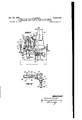
- Fig. 1 is an elevationpartly in section of an apparatus for' testing spur gear drives
- FIG. 1 is a-topplan view 'oi Fig. 1;
- Fig. 4 shows a cross section-of this coupling
- Fig. 5- shows a side elevation of the apparatus illustrated in Figs. 1 and 2-;
- Fig. 6 shows an'elevatibn of' a modified'coupling device for-the rolling cylinders
- Fig. 7 shows an'eleva-tionpartly in 'section'of an apparatus for testing bevel wheel drives
- Fig. 8 is-a view ofthe rolling cylinder shown in Fig. '7 and of the operative connection thereofi Fig. 9showsan e1evation of an apparatus for testingiwormgeandrives;
- Fig;v 11 shows a side: elevation of Fig. 9,.and. Fig.
- an axle 3 is mounted so as to be rotatable with ease.
- the test specimen 4 (advantageously the larger one) is clamped so as to run exactly true to centre.
- the lower end of the axle 3 carries an exchangeable circular disc, that is,-the rolling cylinder 5 of a diameter equalling that of the pitch circle of the test specimen.
- the rolling cylinder 5 is pressed by means of the feed screw 6 against a second rolling cylinder, the axle 8 of whichis mounted in the bed I on ball bearings.
- the second test specimen I2 is fixed to an axle 9 which is mounted in a sleeve [0 which is screwedto a slide I I.
- This slide is supported by means of ball races l3 so as to be movable in the direction at right angles to a plane, which passes through the axes of the two axles 3 and 8, with ease.
- the two axles 8, 9 are coaxially arranged and are coupled together by means of two cross pivot universal joints [4 to 19 (Figs. 2, 3' and- 4)).
- Each cross pivot universal joint is provided with a fork I 4' which is fixed to the axle 8 or 9' respectively.
- a pivot ring [5 is provided with four diametrical bores. Two of said bores are engaged by pins I! which are threadedly connected with the fork I4. With the other two bores.
- ehgages' a bolt l8 which extends through thehub l9of an intermediary member I 5.
- the twin cross pivot universal joint thus formed allows of the axle 9 to perform a slight axial displacement in parallelism with the axle 8 so that the rotational movement is transmitted perfectly unchanged;
- a bolt 20 is secured which transmits movements of the slide that may arise to a lever 2
- a spring 23 acts to urge all the membersinto contacting engagement free from play.
- a scriber point 24 records the displace ments of the slide l I, that is, the specimen I! on a strip of paper which is supported by a" drum 25.
- a power drive is provided'for'the apparatus.
- An electric motor 25 rotates via a worm gear 21, 28 a counter shaft 29 which carriest'wo gears 30 and3l Operatively connected. with these gears are two gears 32 and 33 respectively which by means of' a change-over coupling 34 can'be coupledto a shaft 35 selectively, at will.
- This shaft drives byfmaans? of a pair of bevel wheels 36, 31 a gear 38tthe carrier shaft 39 of which is mounted inthebedi I.
- Inme'sh with said gear 38 are a ge'ar"40;.wliich is fastened to the axle 8 of the rolling cylinder I, and a gear 4I the carrier shaft 42 of which is also mounted in the bed I.
- the upper end of the shaft 42 carries a disc 43 which is frictionally engaged with a disc 44 extending perpendicularly thereto.
- the last named disc is mounted for displacement on the axle 45 of a record carrier drum for the purpose of varying the rotational movement of this drum, that is, the paper feed.
- a set screw 45 During the time of clamping this test specimen I2 in position the movable slide I I is retained in medial position by means of a set screw 45 (Fig. 2).
- this screw is loosened and springs 41 then operate to urge by virtue of shifting movement of a holder 48 for the springs, via an arm 49, the slide II in the required direction.
- the operation of the apparatus will be readily understood.
- the motor 26 slowly rotates by means of the gear 33 the axle 8 and the record carrier drum 25.
- the rolling cylinder 1 transmits this rotational movement of the axle 8 via the rolling cylinder proportional to the ratio between the pitch circles to the test specimen 4 whilst the coaxial axles 8 and 9 and thus also the test specimen I2 have exactly the same velocity of rotation.
- the axles of the two test specimens are adjusted to the prescribed axial distance and under the pressure of the springs 41 on the easily movable slide II the flanks of the respective tooth surfaces enter intermittently into cooperation with each other.
- test specimens and the rolling cylinders mutually interchange their positions, that is to say, the two gears 4 and I2 (Fig. 1) are placed at the lower end of the axles 3 and 8 and the rolling cylinders 5 and I at the upper end of the axles 3 and 9.
- the two gears 4 and I2 (Fig. 1) are placed at the lower end of the axles 3 and 8 and the rolling cylinders 5 and I at the upper end of the axles 3 and 9.
- the drive of the apparatus may be efiected by hand instead of by driving power.
- the rolling cylinders 5 and I may also be made smaller than the pitch circles of the two test specimens 4, I2, but must have the same ratio of gearing. In that event they may be either connected with each other by a thin steel band or by means of rollers 50 and 5! (Fig. 6) which are arranged on forked holders 52, 53 respectively which are carried by an auxiliary slide 54. This slide can be moved in the direction towards the rolling cylinders 5, I on a second side 55 and can be moved by means of said slide 55 in the direction transversely thereto over a slide track 56 on the bed I.
- Fig. '7 an apparatus for testing bevel wheels is shown which operates in a manner similar to that described for spur gears.
- the test specimen axle 9 is connected with the coaxial rolling cylinder axle 8 by a cross pivot universal joint as described above.
- the rolling cylinder I rotates the rolling cylinder 5 via a roller I (Fig. 8) which is sustained by pivotal levers I52, I53 and is urged against the rolling cylinders by.pressure action of a spring I59.
- a conical roller I51 which drives a second roller I58.
- the axle I50 of the latter roller is, for the purpose of pressing the two rollers against each other, mounted in a fork I5I which can be pivotally displaced about the apex of the datum cone.
- the two coaxial axles I62 and I50 are interconnected by means of one of the above described cross pivot universal joints.
- the pair of conical rollers I51, I58 may be replaced by bevel wheels that are configurated perfectly true to form.
- a further pair of rolling cylinders I53, I64 interconnected by an intermediary roller I50 transmits the rotational movement to an axle I03 and thus to the second test specimen I04, the diameter of the rolling cylinders being so chosen, that the speeds of revolution of the test specimens are inversely proportional to the numbers of teeth of the latter.
- the slides I65 and IE6 are adjusted in accordance with the diameters of the bevel wheels.
- the drive is also in this case derived from a motor 20 and transmitted via the axle 8 to the gear 38.
- the rolling cylinder I may rotate the rolling cylinder 5 directly as disclosed in the first exemplification and the intermediary roller I50 associated with the rolling cylinders I63, I64 may in this instance be omitted.
- the worm to be displaced in parallelism with itself for an amount corresponding to the radius of the worm wheel.
- the drive is imparted to the axle of the worm in view of the ratio of gearing of the worm drives being usually great.
- the worm wheel 2I2 is mounted on the shaft 9 of the movable slide II.
- the worm 204 is mounted between centering points in the usual manner and is guided by an arm 268 which is secured to the slide 255.
- a driving member 269 connects the worm shaft with the axle 203. For the fine adjustment of the worm relative to the diameter of the worm wheel andthe center of this wheel slides 266 and 265 are provided.
- the motor 26 rotates via the worm drives 21, 28 and the gears 30, 3I on one hand the record carrier drum 25 and on the other hand via the bevel wheel drive 210, 2' and 212 a fluted shaft 213.
- This shaft is in mesh with a hollow shaft 214 which drives the shaft 203 by means of bevel wheels 215 and 276. Thence the rotational movement is transmitted via the pair of rolling cylinders I64, I03 and the intermediary roller I50 to the axle I62 and via two cross pivot universal joints associated with the intermediary member I I6 to the axle I55.
- Fig; I2 shows: an adjustable friction cone drive for: the apparatus for testin bevel.” wheel's' and worm: drives. If'the diameter-"oflthe various roll ing cylinders do: not precisely correspond to the ratio: of gearing; of the two. test specimens: the curve of errors. recorded would extend on: the skew to the" straight line;
- the friction cone drive provided? permits of correcting the ratio ofi' gearing between all the" measuring cylinders within certain limits mounted" on aslide I 1 91 which slides on thebed' I802
- The: conical roller I?” is displacedifrelative to the axle IBTI' by means: of. two screws ITL l :18 in accordance with. the.
- oppositely disposed transmission means commensurate with faulty gear tooth.configuratiomwhile, the. transmission of. rotationbetween said. two oppcsitelyv disposed transmission.
- means. is main.-.-. tained unaltered ⁇ ancLa-n indicating daviceifor.aocurately recording said displacing, movements of. said. slide intmultipliedproportion 2.
- the friction cone'ro1lenl58 is indersroperativelyr connected with each other: and" connected with supporting: means for rotating;
- pl'acin'g movements ofv said slide in multiplied proportion
- rotation transmission means operatively connected with one saidv gear supporting means extending coaxially with? oppositely disposed rota tion" transmissionv means on the corresponding rolling.
- cylinder a universal joint comprising two; cross: pivot? joints arranged between said op-- p'ositely disposedtransmissionmeans in. succession si'on', a slide slidab'le perpendicularly to the plane through. the. axes of said gcarscarrying said operatively connected supporting and transmission means inclusive of part of said universal joint;
- a motor driven apparatus for testing gears by means of unilateral gear tooth rolling motion control, two rotatable supporting means for a pair of intermeshing gears to be tested, rotated by said motor, rolling cylinders operatively connected with each other and being connected with said supporting means for rotating same at a ratio of gearing corresponding to that of said gears being tested, rotation transmission means operatively connected with one said gear supporting means extending coaxially with oppositely disposed rotation transmission means on the corresponding rolling cylinder, a universal joint arranged between said oppositely disposed transmission means, a slide carrying said operativel connected supporting and transmission means, and allowing the last-named means to be displaced out of coaxiality with the other said oppositely disposed transmission means commensurate with faulty gear tooth configuration, whilethe transmission of rotation between said two oppositely disposed transmission means is maintained unaltered, an indicating device influenced by said motor, and a rotating recording drum carrying recording paper included in said device, permitting feeding of said paper on said drum conjointly with the relative rolling motion between said gears mounted on
Landscapes
- Physics & Mathematics (AREA)
- General Physics & Mathematics (AREA)
- Testing Of Devices, Machine Parts, Or Other Structures Thereof (AREA)
Description
Jan. 23, 1951 D. ERNST 2,539,239
APPARATUS FOR TESTING GEAR DRIVES BY THE METHOD OF UNILATERAL GEAR TOOTH ROLLING MOTION CONTROL Filed May 11, 1945 4 Sheets-Sheet l 12 gmlg 7% 77 74 wuum I, 7/ 77 15 /NYENTOR:
(49M M Ham/"101 Jan. 23, 1951 D. ERNST 2,539,239 PPARATUS FOR TESTING GEAR DRIVES BY THE METHOD OF UNILATERAL GEAR TOOTH ROLLING MOTION CONTROL Filed May 11, 1945 4 Sheets-Sheet 2 F/Ci5 r I I 7 a /52 5 750 30 W 27 INVENIDA:
Jan. 23, 1951 ERNST 2,539,239 APPARATUS FOR TESTING GEAR DRIVES BY THE METHOD OF UNILATERAL GEAR TOOTH ROLLING MOTION CONTROL Filed May 11, 1945 4 Sheets-Sheet 5 i INVf/W'OR:
WWW
Jan. 23, 1951 ERNST APPARATUS FOR TESTING GEAR DRIVES BY THE METHOD OF UNILATERAL GEAR TOOTH ROLLING MOTION CONTRQL Filed May 11, 1945 4 Sheets-Sheet 4 Patented Jan. 23, 1951 APPARATUS FOR TESTING GEAR DRIVES BY THE METHOD OF UNILATERAL GEAR TOOTH ROLLING MOTION CONTROL Daniel Ernst, Zurich, Switzerland, assignor to Maag-Zahnrader und-Maschinen Aktiengesellscha'ft, Zurich, Switzerland Application May 11, 1945, Serial No. 593,210 In Germany April 19, 1944 9 Claims. 1.
This. invention relates to apparatus for testing gear by means of unilateral gear tooth rolling motion control with the aid of rolling cylinders whichare connected with the axles of the test specimens and connected to each other andhave the same ratio of: gearing as the'test specimens. Such an apparatus always indicates any faulty configuration of. those tooth flanks which interengage with each other when rotating in. a certain: direction.
Apparatus-of this kindare known which serve for the testing of spur gear drives- Compared withthesethe apparatus according to the present invention has. the advantage of a wider range of. applicability by being applicable to spur gear driveabevel wheel drives and Worm gear drives as; well; The present apparatus differentiates from the known apparatus in that the axlev of one of the test specimens is. connected with the axle of an associated coaxial rolling cylinder, by means of a universal coupling which allowsof one of said two axles to shift relative to the other axle and transmits the rotational movement unaltered.
Advantageousl'y, the universal coupling'is compo'se'dof' two cross pivot universal joints.
Further,. the displaceable axle is advantageously mounted" on a slide and the shifting movements are visually exhibited by anindicating device in multiplied proportion.
Several embodiments of the invention are illustrated, by way of example only, in the accompanying drawings in which:
Fig; 1 is an elevationpartly in section of an aparatus for' testing spur gear drives;
' Fig; 2 is a-topplan view 'oi Fig. 1;
3 is alongitudinal section of the" universal coupling;
Fig. 4 shows a cross section-of this coupling;
Fig. 5- shows a side elevation of the apparatus illustrated in Figs. 1 and 2-;
Fig. 6 shows an'elevatibn of' a modified'coupling device for-the rolling cylinders;
Fig; 7 shows an'eleva-tionpartly in 'section'of an apparatus for testing bevel wheel drives;
Fig. 8 is-a view ofthe rolling cylinder shown in Fig. '7 and of the operative connection thereofi Fig. 9showsan e1evation of an apparatus for testingiwormgeandrives;
Fig. 10is2a topplanview of Fig. 9;
Fig;v 11 shows a side: elevation of Fig. 9,.and. Fig.
111 firstgexemplification: as shown.- in Figs 1 to; 5,- on? the bed I- of the apparatus a slide 2? is mounted which isadjustablein adaptationto the 12; shows; an' elevation. partlyi in:v section. 0f; adj unable-friction. cone. dliVEL.
distance between thetwo test specimens. In: the slide 2 an axle 3 is mounted so as to be rotatable with ease. To the upper end of this axle one of said spur gears to be tested, that is, the test specimen 4 (advantageously the larger one) is clamped so as to run exactly true to centre. The lower end of the axle 3 carries an exchangeable circular disc, that is,-the rolling cylinder 5 of a diameter equalling that of the pitch circle of the test specimen. The rolling cylinder 5 is pressed by means of the feed screw 6 against a second rolling cylinder, the axle 8 of whichis mounted in the bed I on ball bearings. The second test specimen I2 is fixed to an axle 9 which is mounted in a sleeve [0 which is screwedto a slide I I.
This slide is supported by means of ball races l3 so as to be movable in the direction at right angles to a plane, which passes through the axes of the two axles 3 and 8, with ease. The two axles 8, 9 are coaxially arranged and are coupled together by means of two cross pivot universal joints [4 to 19 (Figs. 2, 3' and- 4)). Each cross pivot universal joint is provided with a fork I 4' which is fixed to the axle 8 or 9' respectively. A pivot ring [5 is provided with four diametrical bores. Two of said bores are engaged by pins I! which are threadedly connected with the fork I4. With the other two bores. ehgages' a bolt l8 which extends through thehub l9of an intermediary member I 5. The twin cross pivot universal joint thus formed allows of the axle 9 to perform a slight axial displacement in parallelism with the axle 8 so that the rotational movement is transmitted perfectly unchanged; On the slide ll" (Fig. 2) a bolt 20 is secured which transmits movements of the slide that may arise to a lever 2| which transmits said move ments to a scriber carrier lever 22 in multiplied proportion. A spring 23 acts to urge all the membersinto contacting engagement free from play. A scriber point 24 records the displace ments of the slide l I, that is, the specimen I! on a strip of paper which is supported by a" drum 25.
As will be s'een' from Figs. 1, 2 and 5 a power drive is provided'for'the apparatus. An electric motor 25 rotates via a worm gear 21, 28 a counter shaft 29 which carriest'wo gears 30 and3l Operatively connected. with these gears are two gears 32 and 33 respectively which by means of' a change-over coupling 34 can'be coupledto a shaft 35 selectively, at will. This shaft drives byfmaans? of a pair of bevel wheels 36, 31 a gear 38tthe carrier shaft 39 of which is mounted inthebedi I.
Inme'sh with said gear 38 are a ge'ar"40;.wliich is fastened to the axle 8 of the rolling cylinder I, and a gear 4I the carrier shaft 42 of which is also mounted in the bed I. The upper end of the shaft 42 carries a disc 43 which is frictionally engaged with a disc 44 extending perpendicularly thereto. The last named disc is mounted for displacement on the axle 45 of a record carrier drum for the purpose of varying the rotational movement of this drum, that is, the paper feed. During the time of clamping this test specimen I2 in position the movable slide I I is retained in medial position by means of a set screw 45 (Fig. 2). During the measuring operation this screw is loosened and springs 41 then operate to urge by virtue of shifting movement of a holder 48 for the springs, via an arm 49, the slide II in the required direction.
The operation of the apparatus will be readily understood. The motor 26 slowly rotates by means of the gear 33 the axle 8 and the record carrier drum 25. The rolling cylinder 1 transmits this rotational movement of the axle 8 via the rolling cylinder proportional to the ratio between the pitch circles to the test specimen 4 whilst the coaxial axles 8 and 9 and thus also the test specimen I2 have exactly the same velocity of rotation. The axles of the two test specimens are adjusted to the prescribed axial distance and under the pressure of the springs 41 on the easily movable slide II the flanks of the respective tooth surfaces enter intermittently into cooperation with each other. If these flanks are erroneously configurated the result will be that the slide I I is displaced in a corresponding amount by the springs 41 (due to the fact that the rota tional movement of both gears takes place a equal velocities of their pitch circles) These slight slide movements are recorded by the scriber point 24 to the paper on the drum 25 in dependence upon the rotational movement of the test specimens in highly multiplied proportion. The respective left hand and right hand tooth flanks can be brought into operative engagement in either direction of rotation simply by changing over the spring holder 40. The rotational velocity is adapted by means of the gears 30, 32, that is, 3|, 33 to the dimensions of the test specimens.
The arrangement may without any further provisions be such that the test specimens and the rolling cylinders mutually interchange their positions, that is to say, the two gears 4 and I2 (Fig. 1) are placed at the lower end of the axles 3 and 8 and the rolling cylinders 5 and I at the upper end of the axles 3 and 9. The operation and the measuring results obtained by this mode of proceeding with the apparatus are similar to those described above.
Alternatively the drive of the apparatus may be efiected by hand instead of by driving power.
The rolling cylinders 5 and I may also be made smaller than the pitch circles of the two test specimens 4, I2, but must have the same ratio of gearing. In that event they may be either connected with each other by a thin steel band or by means of rollers 50 and 5! (Fig. 6) which are arranged on forked holders 52, 53 respectively which are carried by an auxiliary slide 54. This slide can be moved in the direction towards the rolling cylinders 5, I on a second side 55 and can be moved by means of said slide 55 in the direction transversely thereto over a slide track 56 on the bed I. I In Fig. '7 an apparatus for testing bevel wheels is shown which operates in a manner similar to that described for spur gears. As however the axes of the bevel wheels cross each other it is necessary to include between the test specimens a friction cone gearing of the same angle between its axes as that between the test specimens, for the transmission of the rotational movement. The test specimen axle 9 is connected with the coaxial rolling cylinder axle 8 by a cross pivot universal joint as described above. The rolling cylinder I rotates the rolling cylinder 5 via a roller I (Fig. 8) which is sustained by pivotal levers I52, I53 and is urged against the rolling cylinders by.pressure action of a spring I59.
Connected with the rolling cylinder 5 is a conical roller I51 which drives a second roller I58. The axle I50 of the latter roller is, for the purpose of pressing the two rollers against each other, mounted in a fork I5I which can be pivotally displaced about the apex of the datum cone. The two coaxial axles I62 and I50 are interconnected by means of one of the above described cross pivot universal joints. Obviously the pair of conical rollers I51, I58 may be replaced by bevel wheels that are configurated perfectly true to form.
A further pair of rolling cylinders I53, I64 interconnected by an intermediary roller I50 transmits the rotational movement to an axle I03 and thus to the second test specimen I04, the diameter of the rolling cylinders being so chosen, that the speeds of revolution of the test specimens are inversely proportional to the numbers of teeth of the latter. The slides I65 and IE6 are adjusted in accordance with the diameters of the bevel wheels. The drive is also in this case derived from a motor 20 and transmitted via the axle 8 to the gear 38. Alternatively, the rolling cylinder I may rotate the rolling cylinder 5 directly as disclosed in the first exemplification and the intermediary roller I50 associated with the rolling cylinders I63, I64 may in this instance be omitted.
In order to permit of testing worm drives by the apparatus also, all there is necessary is to provide for the axle of the second test specimen,
that is, the worm to be displaced in parallelism with itself for an amount corresponding to the radius of the worm wheel. Advantageously the drive is imparted to the axle of the worm in view of the ratio of gearing of the worm drives being usually great. As shown in Figs. 9, 10 and 11 the worm wheel 2I2 is mounted on the shaft 9 of the movable slide II. The worm 204 is mounted between centering points in the usual manner and is guided by an arm 268 which is secured to the slide 255. A driving member 269 connects the worm shaft with the axle 203. For the fine adjustment of the worm relative to the diameter of the worm wheel andthe center of this wheel slides 266 and 265 are provided.
The motor 26 rotates via the worm drives 21, 28 and the gears 30, 3I on one hand the record carrier drum 25 and on the other hand via the bevel wheel drive 210, 2' and 212 a fluted shaft 213. This shaft is in mesh with a hollow shaft 214 which drives the shaft 203 by means of bevel wheels 215 and 276. Thence the rotational movement is transmitted via the pair of rolling cylinders I64, I03 and the intermediary roller I50 to the axle I62 and via two cross pivot universal joints associated with the intermediary member I I6 to the axle I55. The further course of movement transmission extends via the conical rollers I58, I51 to the first pair of rolling cylinders 5, I and eventually to the worm wheel 2I2 in the same amassemanner as described for" the: apparatus shown in Fi 7 for-the't'esting oflcbevel wheels;
In Fig; 9the iork l 6 I is visible which serves for pressing the conical roller I 58 agai'nst the conical roller" I51; The fork may-'bereplaced hy'a fixed hearing; In this event the: conical roller I58 would be required to beadjustable': longitudinally of its carrier axle I60 and to be acted upon by spring pressure.
Fig; I2 shows: an adjustable friction cone drive for: the apparatus for testin bevel." wheel's' and worm: drives. If'the diameter-"oflthe various roll ing cylinders do: not precisely correspond to the ratio: of gearing; of the two. test specimens: the curve of errors. recorded would extend on: the skew to the" straight line; The friction cone drive provided? permits of correcting the ratio ofi' gearing between all the" measuring cylinders within certain limits mounted" on aslide I 1 91 which slides on thebed' I802 The: conical roller I?! is displacedifrelative to the axle IBTI' by means: of. two screws ITL l :18 in accordance with. the. errors of the" ratio of gearing inconsequence whereof the conical roller 158 is. urged! against the: other conical roller: bymeans ofthe. slide I 19.. In. order to provide for the rollingicylind'er lfi3fwhich-shares in thetmovement of the axle I60 tocorrespondwitnthe rolling cylinder I64 in regard to positioning the former is displaced relative to the. axle [filinzthe oppositev direction to the: adjustment.- oftheiconioal' rollers, This rolling cylinder! is consequentlyafi ranged on a sleeve I81. whichis' correspondingly readjusted. relative to the: axle: and is. firmly clamped inposition byasorew 'cap I82.
I claim:'
1. In a paratus fortesting. gears by means of unilat ral gear tooth rolling. motion controLtwo' rotatable. supporting means for a pair' of intermeshing gears: to be tested. rolling. cylinders" ope erative'ly' connected with; each other: and. connected. with supp'ortingimeans for rotatingsame at a ratio of'gearing corresponding'to that ofsaidgears being tested, rotation: transmission means" operatively connected; with; one :saidgearsupport ing means extending ccaxially- With. oppositely disposed rotation transmission means on the corresponding rolling cylinder, auniversaljoint are rangedbetween said oppositely disposed transmission means,. a-s1ide carrying saidioperatively connected supporting and transmission. means,- and allowing, the last-named means tobe displacedv outof coaxialitywith the. other of said.
oppositely disposed transmission means commensurate with faulty gear tooth.configuratiomwhile, the. transmission of. rotationbetween said. two oppcsitelyv disposed transmission. means. is main.-.-. tained unaltered} ancLa-n indicating daviceifor.aocurately recording said displacing, movements of. said. slide intmultipliedproportion 2. lnlapparatuafor testing earsaby. meanslofi' unilateral gear tooth. rolling. motion. oontroI,, tw.o. rotatable supporting meanafoll. a. pail; of intone meshing gears; to, he: tested.. each extending co The friction cone'ro1lenl58 is indersroperativelyr connected with each other: and" connected with supporting: means for rotating;
same: at: a. ratio of gearing corrcspondingto. that ofsa'id. gears being tested, rotation transmission. means operatively connected. with one saidigear supporting means: extendingv coaxially with op positelyi disposed rotation transmission means on the corresponding: rolling. cylinder; a:. universaljoint comprising" two: crosspivot joints arranged between said: oppositely disposed transmission means in succession, a. slidesslidable perpendicularly'to the plane through. the axesof said gears carrying said. operatively connected supporting" and transmission means inclusive of part'ofsaid universal joint, resilient means cooperating with said slide. for; displacing. same and said trans:- mission means thereon for displacing" the latter outrof: coaxiality with: the other said oppositely disposed transmission means parallelto theraxis of'the" latter commensuratewithiaulty gear tooth;
pl'acin'g movements: ofv said slide in multiplied proportion;
3; In apparatus fortestin'g gears by means-of unilateral. gear tooth. rolling. motion control,v two rotatable supporting. means: for a pair of intermeshing". gears, inclusive of spur and bevel gears;
each .extfending coaxially. withthe. respective said gears, two rolling cylindersoperatively connected with each other and oonnectedwithsaid'supporting: means for rotating same. at aratio of gearing corresponding to that of said gears'being tested;
rotation transmission: means operatively connected with one saidv gear supporting means extending coaxially with? oppositely disposed rota tion" transmissionv means on the corresponding rolling. cylinder, a universal joint comprising two; cross: pivot? joints arranged between said op-- p'ositely disposedtransmissionmeans in. succes si'on', a slide slidab'le perpendicularly to the plane through. the. axes of said gcarscarrying said operatively connected supporting and transmission means inclusive of part of said universal joint;
with one ofisaid pivots in each pivot joint extendinginthedirection of sliding of 'said slide and the other: extending. perpendicularly thereto, spring means cooperating with said slide'for' displacing: same.- and said transmission means thereon for displacing'the' latter out of coaxialitywith the otherrsai'doppositely'disposedtransmission meansparallel to the axis of the lattercommensuratev with faulty gear tooth configuration, while the transmission of rotation Between said two op-- posit'ely disposed transmission means ismaih' tained' unaltered, and an indicating devicefor'accurately recording said displacing movements of" s'aic'fslid'e in multipliedproportion. I
4 In apparatus for testing gears by means of unilateral gear tooth rolling motion control, two rotatah'le'supporting means for two intermeshing gears, inclusive of worm gears; and" worms to be tested; two trains of operatively connected" rolling cylinders extending perpendicularly to each other" and being: operatively' interconnected, and being connected with said supporting means forrotat ing" same ata ratio of gearing corresponding to that ofsaid gearslieing tested, a universal. joint,
a: paiiz, of; coaxial oppositely disposedv rotation.
axially with the respective said gears, rolling cyltransmission of rotation between supporting means,fa slide slidable parallel to the axis of said worm carrying said pair and its correlated supporting means and allowing the transmission means adjoining said supporting means and the other transmission means of said pair to be displaced out of coaxiality,commensurate with faulty gear tooth configuration, while the transmission of rotation between said two oppositely disposed transmission means is maintained unaltered, an indicatin device for recording said displacing movementsof said slide, and a multiplying leverage interposed between said indicating device and said slide, adapted for accurately recording said movements, in multiplied proportion.
5. In apparatus for testing gears by means of unilateral gear tooth rolling motion control, two rotatable supporting for two intermeshing gears, inclusive of bevel and worm gears, and worms to be tested, two trains of operatively connected rolling cylinders extending perpendicularly to each other and being operativelyinterconnected, and being connected with said supporting means for rotating same at a ratio of gearing corresponding to that of said gears being tested, two universal joints, two pairs of coaxial oppositely disposed rotation transmission means interconnected by said universal joints respectivel and correlated to each said gear supporting means, for continually maintaining accurate transmission of rotation between said supporting means, an axled driving cone operated drive, for transmission of rotation between said two trains of cylinders, intercalated between said two trains with its axles extending parallel with the respective said pairs and controlled by one said pair for continually maintaining accuracy of transmission of rotation by said drive, a slide carrying the other said pair and the correlated supporting means and allowing the transmission means adjoining the lastnamcd means and the other transmission means of this pair to be displaced out of coaxiality commensurate with faulty gear tooth configuration, while the transmission of rotation between said two oppositely disposed transmission means is maintained unaltered, an indicating device for recording said displacing movements of said slide and a multiplying leverage interposed between said indicating device and said slide, adapted for accurately recording said movements in multiplied proportion.
6. In apparatus for testing gears by means of unilateral gear tooth rolling motion control, two rotatable supporting means for two intermeshing gears, inclusive of bevel and worm gears, and worms to be tested, two trains of operatively con-- nected rolling cylinders extending perpendicularly to each other and being operatively interconnected, and being connected with said supporting means for rotating same at a ratio of gearing corresponding to that of said ears being tested, two universal joints, two pairs of coaxial oppositely disposed rotation transmission means interconnected by said universal joints respectively, and correlated to each said gear supporting means, for continually maintaining accurate transmission of rotation between said supporting means, an axled driving cone operated drive comprising two beveled rollers intercalated between said two trainsjwith one of its axles extending, coaxial with one of said un ts for the latter to control said drive for continually accurate transmission of rotation by accordingly forcing said rollers into mutual bearing engagement, a slide carrying the other said pair and the correlated supporting means and allowing the transmission 8 means adjoining the last-named means and the other transmission means of this pair to be displaced out of coaxiality commensurate with faulty gear tooth configuration, while the transmission of rotation between said two oppositely disposed transmission means is maintained unaltered, an indicating device for recording said displacing movements of said slide, and a multiplying leverage interposed between said indicating device and said slide, adapted for accurately recording said movements in multiplied proportion.
Z. In a motor driven apparatus for testing gears by means of unilateral gear tooth rolling motion control, two rotatable supporting means for a pair of intermeshing gears to be tested, rotated by said motor, rolling cylinders operatively connected with each other and being connected with said supporting means for rotating same at a ratio of gearing corresponding to that of said gears being tested, rotation transmission means operatively connected with one said gear supporting means extending coaxially with oppositely disposed rotation transmission means on the corresponding rolling cylinder, a universal joint arranged between said oppositely disposed transmission means, a slide carrying said operativel connected supporting and transmission means, and allowing the last-named means to be displaced out of coaxiality with the other said oppositely disposed transmission means commensurate with faulty gear tooth configuration, whilethe transmission of rotation between said two oppositely disposed transmission means is maintained unaltered, an indicating device influenced by said motor, and a rotating recording drum carrying recording paper included in said device, permitting feeding of said paper on said drum conjointly with the relative rolling motion between said gears mounted on said supporting means.
8. In apparatus for testing gears by means of unilateral gear tooth rolling motion control two rotatable supporting means for a pair of intermc-shing gears to be tested, two rolling cylinders of smaller diameter than the pitch circle of the correlated gears, two transmission rollers operativey connecting said cylinders with each other, said rollers being held in accurate peripheral driving contact with each other and with said cylinders, for rotating said cylinders in opposite directions of rotation, forked holders rotatably carrying said rollers, an auxiliary slide pivotally engaging said holders for adjusting and continually maintaining accuracy of said contact by accordingly setting said auxiliary slide, said cylinders being adapted in size and being connected with said supporting means for rotating same at a ratio corresponding to that of said gears being tested, rotation transmission means connected with said gear supporting means extending coaxially with oppositely disposed rotation transmission means on the corresponding rolling cylinder, a universal joint arranged between said oppositely disposed transmission means, a slide carrying said associated supporting and transmission means, and allowing the last-named means to be displaced out of coaxiality with the other said oppositely disposed transmission means commensurate with faulty gear configuration while the transmission of rotation between said two oppositely disposed transmission means is maintained unaltered, an indicating device for recording saiddisplacing movements of said slide,- and a multiplying leverage interposed between said indicating device and said slide, adapted for DANIEL ERNST.
REFERENCES CITED The following references are of record in the file of this patent:
UNITED STATES PATENTS Number Name Date 1,263,472 Saurer Apr. 23, 1918 1,374,698 Wilkinson Apr. 12, 1921 1,394,324 Matthews Oct. 18, 1921 1,479,338 Thomas Jan. 1, 1924 1,911,435 Condon May 30, 1933
Applications Claiming Priority (1)
| Application Number | Priority Date | Filing Date | Title |
|---|---|---|---|
| DE2539239X | 1944-04-19 |
Publications (1)
| Publication Number | Publication Date |
|---|---|
| US2539239A true US2539239A (en) | 1951-01-23 |
Family
ID=7995985
Family Applications (1)
| Application Number | Title | Priority Date | Filing Date |
|---|---|---|---|
| US593210A Expired - Lifetime US2539239A (en) | 1944-04-19 | 1945-05-11 | Apparatus for testing gear drives by the method of unilateral gear tooth rolling motion control |
Country Status (1)
| Country | Link |
|---|---|
| US (1) | US2539239A (en) |
Cited By (6)
| Publication number | Priority date | Publication date | Assignee | Title |
|---|---|---|---|---|
| US2656614A (en) * | 1948-12-15 | 1953-10-27 | Mahr Carl Wilhelm | Testing apparatus for gears |
| US2741034A (en) * | 1953-11-25 | 1956-04-10 | Vinco Corp | Gear testing fixture |
| US2777209A (en) * | 1951-11-09 | 1957-01-15 | Cleveland Hobbing Machine Co | Gear checking apparatus |
| US2855691A (en) * | 1954-11-24 | 1958-10-14 | Frederick W Cunningham | Gear tester |
| US3031765A (en) * | 1958-04-23 | 1962-05-01 | Maag Zahnraeder & Maschinen Ag | Rolling gear tester |
| US3125811A (en) * | 1964-03-24 | Machine for measuring roundness |
Citations (5)
| Publication number | Priority date | Publication date | Assignee | Title |
|---|---|---|---|---|
| US1263472A (en) * | 1915-06-12 | 1918-04-23 | Hippolyt Saurer | Apparatus for testing the teeth of gear-wheels. |
| US1374698A (en) * | 1919-10-16 | 1921-04-12 | Gen Electric | Apparatus for testing gear-wheels |
| US1394324A (en) * | 1920-12-27 | 1921-10-18 | Int Motor Co | Gear-testing machine |
| US1479338A (en) * | 1920-02-04 | 1924-01-01 | John G P Thomas | Method of testing gear wheels, universal joints, and other power-transmitting mechanisms |
| US1911435A (en) * | 1930-09-20 | 1933-05-30 | Gleason Works | Gear testing machine |
-
1945
- 1945-05-11 US US593210A patent/US2539239A/en not_active Expired - Lifetime
Patent Citations (5)
| Publication number | Priority date | Publication date | Assignee | Title |
|---|---|---|---|---|
| US1263472A (en) * | 1915-06-12 | 1918-04-23 | Hippolyt Saurer | Apparatus for testing the teeth of gear-wheels. |
| US1374698A (en) * | 1919-10-16 | 1921-04-12 | Gen Electric | Apparatus for testing gear-wheels |
| US1479338A (en) * | 1920-02-04 | 1924-01-01 | John G P Thomas | Method of testing gear wheels, universal joints, and other power-transmitting mechanisms |
| US1394324A (en) * | 1920-12-27 | 1921-10-18 | Int Motor Co | Gear-testing machine |
| US1911435A (en) * | 1930-09-20 | 1933-05-30 | Gleason Works | Gear testing machine |
Cited By (6)
| Publication number | Priority date | Publication date | Assignee | Title |
|---|---|---|---|---|
| US3125811A (en) * | 1964-03-24 | Machine for measuring roundness | ||
| US2656614A (en) * | 1948-12-15 | 1953-10-27 | Mahr Carl Wilhelm | Testing apparatus for gears |
| US2777209A (en) * | 1951-11-09 | 1957-01-15 | Cleveland Hobbing Machine Co | Gear checking apparatus |
| US2741034A (en) * | 1953-11-25 | 1956-04-10 | Vinco Corp | Gear testing fixture |
| US2855691A (en) * | 1954-11-24 | 1958-10-14 | Frederick W Cunningham | Gear tester |
| US3031765A (en) * | 1958-04-23 | 1962-05-01 | Maag Zahnraeder & Maschinen Ag | Rolling gear tester |
Similar Documents
| Publication | Publication Date | Title |
|---|---|---|
| US3740160A (en) | Numerical controlled boring machine | |
| US2539239A (en) | Apparatus for testing gear drives by the method of unilateral gear tooth rolling motion control | |
| DE2645902B2 (en) | Device for friction and wear testing of material samples | |
| CN119197257A (en) | A gear clearance detection device for reducer | |
| US2108414A (en) | Measuring apparatus | |
| US3572175A (en) | Indexing mechanism | |
| US3069779A (en) | Tester for gears and the like | |
| JPS5861404A (en) | Tester for inspecting form of tooth surface and direction of tooth surface of involute gear of flat tooth or oblique tooth | |
| CN107084897A (en) | A four-point contact bearing ball sliding/rolling friction and wear testing machine for single-drive differential discs with two sets of discs | |
| US2563000A (en) | Lead measuring machine | |
| US2640272A (en) | Contour measuring apparatus | |
| US2171589A (en) | Involute measuring machine | |
| US2602236A (en) | Gear wheel testing apparatus | |
| US2585528A (en) | Apparatus for testing gear teeth | |
| US1444470A (en) | Apparatus for testing gear wheels | |
| US3188745A (en) | Tooth space measuring machine | |
| US1907957A (en) | Cylinder and pipe cutting machine | |
| US1263472A (en) | Apparatus for testing the teeth of gear-wheels. | |
| US2815580A (en) | Instrument for testing rotation of conical wheels | |
| US1805740A (en) | Drafting machine | |
| US2656614A (en) | Testing apparatus for gears | |
| SU530770A1 (en) | A device for welding fixed pipe joints | |
| CN218916152U (en) | Flanging bearing bush width measuring device | |
| US1701184A (en) | Method and apparatus for testing gears | |
| GB444209A (en) | Device for testing toothed gears intended for co-operation, by means of which angular velocity faults occurring during co-running are ascertained |