US2536595A - Portable spin riveting tool - Google Patents
Portable spin riveting tool Download PDFInfo
- Publication number
- US2536595A US2536595A US701318A US70131846A US2536595A US 2536595 A US2536595 A US 2536595A US 701318 A US701318 A US 701318A US 70131846 A US70131846 A US 70131846A US 2536595 A US2536595 A US 2536595A
- Authority
- US
- United States
- Prior art keywords
- tool
- piston
- piston member
- rivet
- peen
- Prior art date
- Legal status (The legal status is an assumption and is not a legal conclusion. Google has not performed a legal analysis and makes no representation as to the accuracy of the status listed.)
- Expired - Lifetime
Links
Images
Classifications
-
- B—PERFORMING OPERATIONS; TRANSPORTING
- B23—MACHINE TOOLS; METAL-WORKING NOT OTHERWISE PROVIDED FOR
- B23Q—DETAILS, COMPONENTS, OR ACCESSORIES FOR MACHINE TOOLS, e.g. ARRANGEMENTS FOR COPYING OR CONTROLLING; MACHINE TOOLS IN GENERAL CHARACTERISED BY THE CONSTRUCTION OF PARTICULAR DETAILS OR COMPONENTS; COMBINATIONS OR ASSOCIATIONS OF METAL-WORKING MACHINES, NOT DIRECTED TO A PARTICULAR RESULT
- B23Q5/00—Driving or feeding mechanisms; Control arrangements therefor
- B23Q5/02—Driving main working members
- B23Q5/04—Driving main working members rotary shafts, e.g. working-spindles
- B23Q5/06—Driving main working members rotary shafts, e.g. working-spindles driven essentially by fluid pressure or pneumatic power
-
- B—PERFORMING OPERATIONS; TRANSPORTING
- B21—MECHANICAL METAL-WORKING WITHOUT ESSENTIALLY REMOVING MATERIAL; PUNCHING METAL
- B21J—FORGING; HAMMERING; PRESSING METAL; RIVETING; FORGE FURNACES
- B21J15/00—Riveting
- B21J15/02—Riveting procedures
-
- B—PERFORMING OPERATIONS; TRANSPORTING
- B21—MECHANICAL METAL-WORKING WITHOUT ESSENTIALLY REMOVING MATERIAL; PUNCHING METAL
- B21J—FORGING; HAMMERING; PRESSING METAL; RIVETING; FORGE FURNACES
- B21J15/00—Riveting
- B21J15/10—Riveting machines
- B21J15/105—Portable riveters
-
- B—PERFORMING OPERATIONS; TRANSPORTING
- B21—MECHANICAL METAL-WORKING WITHOUT ESSENTIALLY REMOVING MATERIAL; PUNCHING METAL
- B21J—FORGING; HAMMERING; PRESSING METAL; RIVETING; FORGE FURNACES
- B21J15/00—Riveting
- B21J15/10—Riveting machines
- B21J15/12—Riveting machines with tools or tool parts having a movement additional to the feed movement, e.g. spin
-
- B—PERFORMING OPERATIONS; TRANSPORTING
- B21—MECHANICAL METAL-WORKING WITHOUT ESSENTIALLY REMOVING MATERIAL; PUNCHING METAL
- B21J—FORGING; HAMMERING; PRESSING METAL; RIVETING; FORGE FURNACES
- B21J15/00—Riveting
- B21J15/10—Riveting machines
- B21J15/16—Drives for riveting machines; Transmission means therefor
- B21J15/18—Drives for riveting machines; Transmission means therefor operated by air pressure or other gas pressure, e.g. explosion pressure
-
- B—PERFORMING OPERATIONS; TRANSPORTING
- B23—MACHINE TOOLS; METAL-WORKING NOT OTHERWISE PROVIDED FOR
- B23Q—DETAILS, COMPONENTS, OR ACCESSORIES FOR MACHINE TOOLS, e.g. ARRANGEMENTS FOR COPYING OR CONTROLLING; MACHINE TOOLS IN GENERAL CHARACTERISED BY THE CONSTRUCTION OF PARTICULAR DETAILS OR COMPONENTS; COMBINATIONS OR ASSOCIATIONS OF METAL-WORKING MACHINES, NOT DIRECTED TO A PARTICULAR RESULT
- B23Q11/00—Accessories fitted to machine tools for keeping tools or parts of the machine in good working condition or for cooling work; Safety devices specially combined with or arranged in, or specially adapted for use in connection with, machine tools
- B23Q11/0042—Devices for removing chips
- B23Q11/005—Devices for removing chips by blowing
Definitions
- a further objectof'rny invention is to provide vanes and high velocityair-jetsin the tool motor torotate the power element of the tool simul taneously with its" percussiveor hammering action'.
- the air exhausts form the vanes 46 on the exhaust side of the rotor at ports 2
- the ports 39, 39 are never closed by reciprocation of the piston 6 on its forward and return strokes but are operably connected at all times to the piston spaces or areas between the smaller and larger pressure areas 26 and 29. This means that air under pressure is constantly passing through the ports 39, 39 and applied to the piston vanes 40, 40 so as to cause rotation of the piston at all times during its upstrokes and downstrokes.
Description
R. DITTMANN PORTABLE SPIN RIVETING TOOL Filed Oct. 4, 1946 INVENTOR. Rov DITTMANN BY ATTORNEY Patented Jan. 2, 1951 UNITED 1 STATE;
optics 2,536,595 PORTABLE SPIN RIVETING TOOL Roy Dittrna'nn, Aurora, 111., assign or to Independent Pneumatic Tool' Company, Chicago, 111., a
corporation of Delaware Application ctober4, 1946, Serial No. 701,318
ativ'ely' soft body material where the rivet is backed-up at its preformed or manufactured head; but where the soft material provides little or ndsidewise' or'lateral support to revent'benqing of the rivet stem in'riveting long thin rivets in ironing boards, army cots; certain types of trunks and'cratesand many similar items.
A further object of my invention is to provide a'spin' riveting tool in which the tool operates on the simultaneously spin and vibration'principle to form the rivet heads on the rivets.
A further" objectof'rny invention is to provide vanes and high velocityair-jetsin the tool motor torotate the power element of the tool simul taneously with its" percussiveor hammering action'.
A further object of my invention is to provide an improved motor structure for use' in these portable spin riveting tools.
The invention consists further in the structural features and combinations of parts hereinafter described and claimed. I
In the accompanying drawing:
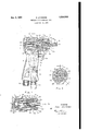
Fig.1 isa side elevation'al'view partly in vertical'section taken on line I''-I' of Fig; 2' of a portable power actuatedspin riveting tool constructed in accordance with my invention;
Fig. 2 is a diametric sectional view taken through the motor section of the tool on line 2-2 of Fig." 1; and
Fig: 3 is a sectional view similar to that of Fig.
1, except that the piston 'member'of the'tool is shown at the end of its forward orriveting stroke to. be hereinafter described; j 7 I Asshown in thedrawing, the tool of my in-' vention comprises connected 'body and handle portions I, 2, the body-portion 'I being at one end of the tool andthe' handle po'rtion2 extending to the opposite end of the tool as shown in Fig. 1. The body and handle portions 1, 2"are preferablyintegrally connected together, being in onepiece asshown in Fig: 1. The body-portion 'I is made to mount and support the motor unit 3 of the tool, said unit extending-laterallyto one side 10 thus'permit the formation of a rivet head in a rel- V of th'e' handleportion -z* andcoiiiprise'd-of an"'as="- sembly of inner and outer sleeves or barrels 4, 5
andapiston memberji located within the inner sleeve 4 as shown herein. p
The outer sleeve or barrel, 5 has a' screw threaded connection I with the body portion I within the recess or cavity into which said sleeves or barrelsare inserted. This threaded connectionl of the outer sleeve 5 with the body portion I enables the outerbarrel 5 tobescrewed tightly into the tool and tightly clamp the inner.
The inner sleeve l provides a cylinder ID for the piston member 6. The cylinder IIl is co-extensive with the length of the inner sleeve 4 andv is closed at-its opposite ends by the end wall 8 and the boss 9, respectively. The piston member 6 is revolubly and reciprocably mounted in the cylinder I0 and has a rigid piston rod I I extend-1 ing outwardly of the tool throug'h the end wall- 8 :of the outer sleeve or barrel 5 as illustrated in Figs. 1 and 3.
Fitted on the outer end of therod II isa rivet headforming peen I 2 ha ving a complement of radially disposed prongs I 3. The peens em-@ ployed with the toolmay have two, fouriorsix prongs and the edges thereof are protected from cracking off under shock in the operation of they tool by a steel ring or band I4 pressed on the peen I2 as shownin Fig.1. shaped as shown andthe cupping of the peen depends on the type of rivet head to be formed by the tool. V Y
The sleeves 4, 5'are substantially complementary in length and extend at their inner ends into a chamber or channel I5 formed in the body portion I. about the boss 9 as shown innFigs. 1
and 3. Thechamber or channel I5 supplies com-g pressed air to the tool motor 3 to operate it through a longitudinally extending passage I 6 in the'l'outer surface of the inner sleeve 4 between the same and the outer sleeve 5 as shown in Figs,"
1 and 3. The channel I5 connects with the com pressed air supply passage I! in the handle portion 2 of the tool as shownin Fig. 1. This, passa e Ii connects with a passage I8, also in the handle 2, through a spring: biased thr-ottle valve I9 mounted in thehandle between said passagesas indicated 'in' dotted line'sin Fig. 1. The assage" I8'lea'd's to a nipplefi'iit'ure 20" secured to the outer end of the handle 2 for connection with the air supply hose (not shown) of thetool.
Mounted n e handle 2 in the supply system The peen I2, is cupof the tool is an air regulator 2| of the character disclosed in the F. P. Forss Patent No. 2,369,779, granted Feb. 20, 1945, to the assignee of the instant application. The valve l9 has stem 22 which is depressed to open the valve by the interaction of a lever 23 and a plunger or trigger 24 accessible at the outer side of the tool handle 2 to control the supply of fluid pressure to the tool motor for operating it.
Live air supplied to the tool handle 2 travels along the passage [6 from the channel 55 to a port 25 in the inner sleeve 6 and enters the cylinder about the piston member in advance of an abutment surface or shoulder 26 on said piston as shown in Fig. 1. Live air acting on said abutment surface 26 forces the piston 6 towards the inner end of the cylinder ill for the return stroke of the piston as shown in Fig. 1. As the piston 6 travels rearwardl on its return stroke, ports 21 in the piston allow live air to enter the bore 23 within the piston and act on the larger pressure area 29 at the rear end the piston and force the same forwardly on its power or riveting stroke. To accomplish this motion of the piston 6, the bore 28 is arranged axially of the piston and opens through the rear end thereof on which said larger pressure area 29 is provided. As soon as the pressure action of the live air on the larger pressure area 29 overcomes that on the smaller pressure area 26, the piston 6 is automatically driven on its forward or riveting stroke as shown in Fig. 3.
As the piston 6 travels forward on its riveting stroke, ports 21 in the piston are cut off from the supply port 25 when the diameter 35 of the piston enters the complementary diameter 35 of the cylinder I0 which diameter 3! is forward of the port 25 as herein shown. This forward movement of the piston 6 continues until the ports 2! are brought into connection or registration with ports 32 in the inner sleeve 4, whereupon the rear end of the cylinder Iii exhausts to the atmosphere through said ports 32 and their respective passages 33, 34 in the outer surface of the inner sleeve 4 between the same and the outer sleeve 5 as shown in Fig. 2. Passages 33, 34 open through the front end of the inner sleeve 6 into a channel 35 which connects with exhaust ports 36 in the end wall 8 of the outer sleeve 5 about the piston rod 1 I as shown in Figs. 1 and 3. The channel 35 in the embodiment shown is partly in the end wall 8 and partly in the surrounding wall of the outer sleeve 5. The front end of the cylinder IE! beyond the piston 6 is constantly connected with either or both of the exhaust passages 33, 34 by a port or ports 31.
The piston action is of the vibratory character serving with relatively short and rapid strokes, plus its rotary action to be later described, to upset the ends of relatively long, thin rivets in relatively soft materials like rubber, fiber or wood without the necessity of such soft materials supporting the rivets between their heads to prevent bending under the force of riveting operation. The length of travel of the piston 6 is approximately the distance between the ports 25 and 32 in the inner sleeve 4. The pressure changes on the piston 6 are rapid, being automatically controlled by the reciprocal movement of the piston within the inner sleeve 4. Hence, the tool develops an intermittent hammering action of an extent suflicient to upset and form a rivet head on long, thin rivets without supporting the rivets, except by backing-up at their pre-formed headed ends.
The smaller pressure area 26 of the piston 6 is constantly exposed to the live air in all positions of the piston 6 as will be noted in Figs. 1 and 3 and the supply source for both rearward and riveting strokes of the piston 3 is through the port 25 and its passage l6. Hence, when the rear end of the cylinder Ii) exhausts through the ports 32, the piston 5 will immediately and automatically be returned on its return stroke by the live air acting on the smaller pressure area 255. And this action of the tool automatically repeats without the need of a control valve.
For rotating the piston 6 simultaneously with its reciprocation to form the head of rivet being made by the tool, live air from the channel 55 enters a passage 38 in the inner sleeve 4 and travels to ports 39, 39 arranged side by side in the inner sleeve 3 and of relatively small diameter to provide for discharge of high velocity jets of live air against the operative surfaces of radially disposed vanes 49, 40 on the outer side of the piston 6 intermediate the smaller and larger pressure areas 26 and 29, respectively. These ports 39, as shown in Fig. 2, are arranged to discharge their jets across the piston 6 in a substantially tangential direction to rotate the piston at a relativel high speed to form the upset material into a rivet head in conformity with the cup-shape of the peen member [2 being used. The air exhausts form the vanes 46 on the exhaust side of the rotor at ports 2| connected with a passage 42 in the inner sleeve i and opening into the exhaust systerm 35, 35 of the tool as shown in Fig. 2. It is to be noted from Figs. 1 and 3 of the drawings that the ports 39, 39 are never closed by reciprocation of the piston 6 on its forward and return strokes but are operably connected at all times to the piston spaces or areas between the smaller and larger pressure areas 26 and 29. This means that air under pressure is constantly passing through the ports 39, 39 and applied to the piston vanes 40, 40 so as to cause rotation of the piston at all times during its upstrokes and downstrokes.
The spin riveting tool of my invention as herein shown and described is simple and inexpensive in construction and embodies in a relatively light portable tool a vibratory and rotative rivetive action as required for heading rivets in relatively soft body materials without bending as before mentioned.
The details of construction and arrangements of the parts shown and described may be variousl changed and modified without departing from the spirit and scope of m invention, except as pointed out in the annexed claims.
I claim as my invention:
1. A portable hand held power actuated riveting tool comprising, connected body and handle portions, motor means mounted in and supported by the body portion of the tool and including a power element, a peen carried thereby, means for simultaneously rotating and reciprocating said power element with a relatively rapid vibratory stroke for upsetting and forming by the peen a rivet head on the stem of a rivet in a relatively soft body material without necessitating lateral support for the rivet stem between its ends, said means for rotating said power element being operably connected therewith at all times for effecting rotation of said power element on its power and return strokes, and control means for the motor carried by the tool.
2. A portable hand held power actuated riveting tool comprising, connected body and bane dle portions, motor meansmounted in and supported by the body portion of the tool and including a piston member having a rod extending out wardly of the tool, a'peen on said rod, means for simultaneously rotating and reciprocating the piston member with a relatively rapid vibratory stroke for upsetting and forming by means of the peen a rivet head on the stem of a rivet in a relatively soft body material without necessitating lateral support for the rivet stem between its ends, said means for rotating said piston member being operably connected at all times for effecting rotation of said piston member on its power and return strokes, and control means for the motor carried by the tool.
3. A portable hand held power actuated riveting tool comprising, connected body and handle portions, motor means mounted in and supported by the body portion of the tool and including a piston member having a rod extending outwardly of the tool, a peen on the rod, said piston member having differential pressure areas and vanes therebetween, means for supplying fluid pressure to said responsive vanes and areas for simultaneously rotating and reciprocating the piston member with a relatively rapid vibratory stroke for upsetting and forming by the peen a rivet head on the stem of a rivet in a body mate rial, said fluid pressure supplying means being operably connected at all times with said vanes to supplying fluid pressure thereto at all times for efiecting rotation of said piston member on its power and return strokes, and means for controlling the supply of fluid pressure to the piston member.
4. A portable hand held power actuated riveting tool comprising, connected body and handle portions, motor means including inner and outer barrels mounted in and supported by the body portion of the tool and a piston member operatively mounted within the inner barrel, the outer barrel securing the motor means in place and the inner barrel within the outer barrel, a peen carried by the piston member, means for simultaneously rotating and reciprocating the piston member with a relatively rapid vibratory stroke within the inner barrel for upsetting and forming by the peen a rivet head on the stem of a rivet in a body material, said means for rotating said piston member being operably connected therewith at all times for effecting rotation of said piston member on its power and return strokes, and control means for the motor carried by the tool.
5. A portable hand held power actuated riveting too1 comprising, connected body and handle portions, motor means having inner and outer barrels mounted in and supported by the body portion of the tool and a piston member operatively mounted within the inner barrel, the outer barrel having an end wall extening over and closing the outer end of the inner barrel and engaging the same for holding the inner barrel within the outer barrel, a rod fixed to the piston member and extending outwardly of the tool through said end wall, a peen on the rod, means for simultaneously rotating and reciprocating said piston member with a relatively rapid vibratory stroke for upsetting and forming by the peen a rivet head on the stem of a rivet in a body material, said means for rotating said piston member being operably connected therewith at all times for effecting rotation of said piston member on its power and return strokes, and means carried by 6 the tool for controlling the operation of the motor.
6. A portable hand held power actuated riveting too1 comprising, connected body and handle portions, motor means having inner and outer barrels mounted in and supported by the body portion of the tool and a piston member operatively mounted within the inner barrel, a seat in the body portion of the tool for closing the inner end of the inner barrel, the outer barrel having screwed connection with the body portion of the tool and having an end wall closing and engaging the outerend of the inner barrel for clamping the inner barrel against said seat, means for simultaneously rotating and reciprocating the piston member with a relatively short vibratory stroke, said means for rotating said piston member being operably connected therewith at all times for efiecting rotation of said piston member on its power and return strokes, a peen operatively connected with said piston member for forming a rivet head on the stem of a rivet, and control means for the motor carried by the tool.
7. A portable hand held power actuated riveting tool comprising, connected body and handle portions, motor means having inner and outer barrels mounted in and supported by the body portion of the tool and a piston member operatively mounted within the inner barrel, said piston member having means for simultaneously rotating and reciprocating the same with a relatively rapid vibratory stroke on supplying fluid pressure to said piston member, the inner barrel having ports and passages for supplying fluid pressure to the inner barrel for operation of said piston member, said ports for supplying fluid pressure for efiecting rotation of said piston member being open at all times during the power and return strokes of the piston member to effect rotation of said piston member during such strokes, a peen operatively connected with the piston member for upsetting and forming a rivet head on the stem of a rivet, and means carried by the tool for controlling the supply of fluid pressure to the barrels.
8. A portable hand held power actuated riveting tool comprising, connected body and handle portions, motor means having inner and outer barrels mounted in the body portion of the tool and a piston member operatively disposed within the inner barrel, said piston member having means for simultaneously rotating and reciprocating the same with a relatively rapid stroke in response to fluid pressure admitted to the piston member from between the inner and outer barrels, said inner barrel having inlet and exhaust passages for the fluid pressure, the inlet passages being between the two barrels and serving to receive fluid pressure from one end of the inner barrel, and certain of said inlet and exhaust passages being operably connected at all times to the piston member during the power and return strokes of the piston member to efiect rotation of said piston member during such strokes, a peen carried by the piston member for forming a rivet head on the stem of a rivet, and means carried by the tool for controlling the supply of fluid pressure to said barrels.
9. A portable hand held power actuated riveting tool comprising, connected body and handle portions, motor means having inner and outer barrels mounted in and supported by the body portion of the tool and a piston member operatively disposed within the inner barrel said body portion having a seat for the inner barrel and a supply channel about the same, said piston member having means for simultaneously rotating and reciprocating the same with a-relatively rapid vibratory stroke in-response to fluid pres-' sure-admitted to the piston member from between the inner and outer barrels, said inner barrel having inlet and exhaust passages for the fluid pressure,-the inlet passages being between the barrels and openinginto the supply channel about the-seat onthe body portion at the inner end of theinner barrel, certain of saidinlet and exhaust passages being open and connected at all times with said piston member during the powerand return strokes'thereof to effect rotation of said piston member during such strokes, a peen-carried by the piston member for forming arivet'head on the'stem of arivet, and'means carried by the tool'for controlling the supply of fluid pressure to the barrels.
10.- Aportable hand held power actuated riveting tool comprising, connected body and handle portions," motor means having inner and outer barrels mounted in and supported by the body portion of the tool and a'piston member operativel-y disposed within the inner barrel, said inner-barrel providing acylinder for said piston member, said outer barrel having an end wall closing the outer end of said cylinder and engag-- ing'the'adjacentend of the inner barrel for holding the-same in'place, means on the piston member for simultaneously rotating and reciprocating the same with a relatively rapid vibratory stroke in response to fluid pressure admitted to said cylinder, inlet and exhaust passages for the fluid pressure in'the inner barrel and exhaust ports in the end wall of the outer barrel about its REFERENCES CITED The following references are of record in the file of'this patent:
UNITED'STATES PATENTS Number Name Date 585,960 Kidd July 6, 1897 1,324,327 Turner Dec. 9, 1919 1,702,750 Stumf Feb. 19, 1929 1,910,95 Knuuti May 23, 1933 1,971,773 De Mooy Aug. 28, 1934 2,402,212 Shaff June 18, 1946 2,404,051 Ginter July 16, 1946 2,433,719 Van Sittert Dec. 30, 1947
Priority Applications (1)
| Application Number | Priority Date | Filing Date | Title |
|---|---|---|---|
| US701318A US2536595A (en) | 1946-10-04 | 1946-10-04 | Portable spin riveting tool |
Applications Claiming Priority (1)
| Application Number | Priority Date | Filing Date | Title |
|---|---|---|---|
| US701318A US2536595A (en) | 1946-10-04 | 1946-10-04 | Portable spin riveting tool |
Publications (1)
| Publication Number | Publication Date |
|---|---|
| US2536595A true US2536595A (en) | 1951-01-02 |
Family
ID=24816883
Family Applications (1)
| Application Number | Title | Priority Date | Filing Date |
|---|---|---|---|
| US701318A Expired - Lifetime US2536595A (en) | 1946-10-04 | 1946-10-04 | Portable spin riveting tool |
Country Status (1)
| Country | Link |
|---|---|
| US (1) | US2536595A (en) |
Cited By (12)
| Publication number | Priority date | Publication date | Assignee | Title |
|---|---|---|---|---|
| US2739570A (en) * | 1951-02-02 | 1956-03-27 | Virgil L Frantz | Automatic bell ringer |
| US2824547A (en) * | 1953-12-10 | 1958-02-25 | Indianapolis Bond And Share Co | Portable spinning rivet hammer |
| US2872902A (en) * | 1956-02-20 | 1959-02-10 | Thomas H Morgan | Vibrator |
| US3057331A (en) * | 1959-02-18 | 1962-10-09 | White Sales Corp Graham | Pneumatic motor |
| US3099186A (en) * | 1960-07-21 | 1963-07-30 | Cooper Bessemer Corp | Marking device |
| US3164903A (en) * | 1960-04-07 | 1965-01-12 | Charles A Ellis | Dental handpiece |
| US4191093A (en) * | 1977-09-19 | 1980-03-04 | Compton Marshall F | Concrete strike-off vibrator |
| US4651833A (en) * | 1983-12-01 | 1987-03-24 | Emil Schenker Ag | Pneumatic impact tool |
| FR2678197A1 (en) * | 1991-06-26 | 1992-12-31 | Recoules Automation | Automatic riveting machine |
| WO1999061790A1 (en) * | 1998-05-22 | 1999-12-02 | Sedlacek Miroslav | Hydraulic motor |
| CN1102999C (en) * | 1998-05-22 | 2003-03-12 | 米罗斯拉夫·塞德拉切克 | Hydraulic motor |
| CN100584480C (en) * | 2008-10-29 | 2010-01-27 | 济南易恒技术有限公司 | Hub unit radial digital control rotary riveting equipment |
Citations (8)
| Publication number | Priority date | Publication date | Assignee | Title |
|---|---|---|---|---|
| US585960A (en) * | 1897-07-06 | Direct-acting engine | ||
| US1324327A (en) * | 1919-12-09 | Lubricating arrangement for pneumatic rock-drills | ||
| US1702750A (en) * | 1925-10-15 | 1929-02-19 | Black & Decker Mfg Co | Portable power-driven rivet spinning and pressing tool |
| US1910954A (en) * | 1929-12-26 | 1933-05-23 | Western Electric Co | Percussive apparatus |
| US1971773A (en) * | 1931-04-09 | 1934-08-28 | Cleveland Pneumatic Tool Co | Riveting machine |
| US2402212A (en) * | 1942-08-12 | 1946-06-18 | Keller Tool Co | Operation controlling means for pressure fluid actuated tools |
| US2404051A (en) * | 1943-11-03 | 1946-07-16 | Aro Equipment Corp | Blind riveter |
| US2433719A (en) * | 1944-03-09 | 1947-12-30 | Reed Roller Bit Co | Valve control mechanism for pressure fluid motors |
-
1946
- 1946-10-04 US US701318A patent/US2536595A/en not_active Expired - Lifetime
Patent Citations (8)
| Publication number | Priority date | Publication date | Assignee | Title |
|---|---|---|---|---|
| US585960A (en) * | 1897-07-06 | Direct-acting engine | ||
| US1324327A (en) * | 1919-12-09 | Lubricating arrangement for pneumatic rock-drills | ||
| US1702750A (en) * | 1925-10-15 | 1929-02-19 | Black & Decker Mfg Co | Portable power-driven rivet spinning and pressing tool |
| US1910954A (en) * | 1929-12-26 | 1933-05-23 | Western Electric Co | Percussive apparatus |
| US1971773A (en) * | 1931-04-09 | 1934-08-28 | Cleveland Pneumatic Tool Co | Riveting machine |
| US2402212A (en) * | 1942-08-12 | 1946-06-18 | Keller Tool Co | Operation controlling means for pressure fluid actuated tools |
| US2404051A (en) * | 1943-11-03 | 1946-07-16 | Aro Equipment Corp | Blind riveter |
| US2433719A (en) * | 1944-03-09 | 1947-12-30 | Reed Roller Bit Co | Valve control mechanism for pressure fluid motors |
Cited By (13)
| Publication number | Priority date | Publication date | Assignee | Title |
|---|---|---|---|---|
| US2739570A (en) * | 1951-02-02 | 1956-03-27 | Virgil L Frantz | Automatic bell ringer |
| US2824547A (en) * | 1953-12-10 | 1958-02-25 | Indianapolis Bond And Share Co | Portable spinning rivet hammer |
| US2872902A (en) * | 1956-02-20 | 1959-02-10 | Thomas H Morgan | Vibrator |
| US3057331A (en) * | 1959-02-18 | 1962-10-09 | White Sales Corp Graham | Pneumatic motor |
| US3164903A (en) * | 1960-04-07 | 1965-01-12 | Charles A Ellis | Dental handpiece |
| US3099186A (en) * | 1960-07-21 | 1963-07-30 | Cooper Bessemer Corp | Marking device |
| US4191093A (en) * | 1977-09-19 | 1980-03-04 | Compton Marshall F | Concrete strike-off vibrator |
| US4651833A (en) * | 1983-12-01 | 1987-03-24 | Emil Schenker Ag | Pneumatic impact tool |
| FR2678197A1 (en) * | 1991-06-26 | 1992-12-31 | Recoules Automation | Automatic riveting machine |
| WO1999061790A1 (en) * | 1998-05-22 | 1999-12-02 | Sedlacek Miroslav | Hydraulic motor |
| CN1102999C (en) * | 1998-05-22 | 2003-03-12 | 米罗斯拉夫·塞德拉切克 | Hydraulic motor |
| US6702038B1 (en) | 1998-05-22 | 2004-03-09 | Miroslav Sedlacek | Hydraulic motor |
| CN100584480C (en) * | 2008-10-29 | 2010-01-27 | 济南易恒技术有限公司 | Hub unit radial digital control rotary riveting equipment |
Similar Documents
| Publication | Publication Date | Title |
|---|---|---|
| US2536595A (en) | Portable spin riveting tool | |
| US2019964A (en) | Cushion means for tools | |
| US2413542A (en) | Pressure fluid driven tool | |
| US2555018A (en) | Pneumatic saw and the like | |
| SE7503038L (en) | SLIDING DRILLING KIT AND DEVICE FOR DAMPING REFLEXES FROM A WORKING TOOL | |
| US2674098A (en) | Portable power-driven tool for drilling and like operations | |
| US5337837A (en) | Dual-diameter pneumatic ground piercing tool | |
| US1901779A (en) | Power hammer | |
| US1167975A (en) | Pneumatic-tool piston. | |
| US2462155A (en) | Chuck | |
| US1191948A (en) | Power-hammer. | |
| US1800465A (en) | Power hammer | |
| US2944521A (en) | Pneumatic peening and marking tool | |
| US3086501A (en) | Fluid-operated hammer | |
| US2731636A (en) | Improvements in explosively actuated fastener driving tools | |
| US2655901A (en) | Pneumatic hammer | |
| US1440082A (en) | Fluid-actuated hammer | |
| US893138A (en) | Pneumatic tool. | |
| US1599628A (en) | Massaging apparatus | |
| GB2114495A (en) | Impact tool | |
| US1537358A (en) | Surface-treating tool | |
| US2126829A (en) | Mechanical hammer | |
| US1207417A (en) | Mechanical hammer. | |
| US687851A (en) | Impact-tool. | |
| US1126096A (en) | Pneumatic hammer. |