US2528811A - Earphone - Google Patents
Earphone Download PDFInfo
- Publication number
- US2528811A US2528811A US584272A US58427245A US2528811A US 2528811 A US2528811 A US 2528811A US 584272 A US584272 A US 584272A US 58427245 A US58427245 A US 58427245A US 2528811 A US2528811 A US 2528811A
- Authority
- US
- United States
- Prior art keywords
- shell
- ear
- receiver
- diaphragm
- pinna
- Prior art date
- Legal status (The legal status is an assumption and is not a legal conclusion. Google has not performed a legal analysis and makes no representation as to the accuracy of the status listed.)
- Expired - Lifetime
Links
- 239000013078 crystal Substances 0.000 description 11
- 238000010276 construction Methods 0.000 description 5
- 206010011878 Deafness Diseases 0.000 description 2
- 230000010355 oscillation Effects 0.000 description 2
- 239000004020 conductor Substances 0.000 description 1
- 239000000645 desinfectant Substances 0.000 description 1
- 230000005484 gravity Effects 0.000 description 1
- 230000004886 head movement Effects 0.000 description 1
- 239000003562 lightweight material Substances 0.000 description 1
- 239000000696 magnetic material Substances 0.000 description 1
- 239000000463 material Substances 0.000 description 1
- 238000000034 method Methods 0.000 description 1
- 239000002991 molded plastic Substances 0.000 description 1
- 239000004033 plastic Substances 0.000 description 1
- 229920003023 plastic Polymers 0.000 description 1
- LJCNRYVRMXRIQR-OLXYHTOASA-L potassium sodium L-tartrate Chemical compound [Na+].[K+].[O-]C(=O)[C@H](O)[C@@H](O)C([O-])=O LJCNRYVRMXRIQR-OLXYHTOASA-L 0.000 description 1
- 235000011006 sodium potassium tartrate Nutrition 0.000 description 1
- 239000007787 solid Substances 0.000 description 1
Images
Classifications
-
- H—ELECTRICITY
- H04—ELECTRIC COMMUNICATION TECHNIQUE
- H04R—LOUDSPEAKERS, MICROPHONES, GRAMOPHONE PICK-UPS OR LIKE ACOUSTIC ELECTROMECHANICAL TRANSDUCERS; DEAF-AID SETS; PUBLIC ADDRESS SYSTEMS
- H04R11/00—Transducers of moving-armature or moving-core type
-
- H—ELECTRICITY
- H04—ELECTRIC COMMUNICATION TECHNIQUE
- H04R—LOUDSPEAKERS, MICROPHONES, GRAMOPHONE PICK-UPS OR LIKE ACOUSTIC ELECTROMECHANICAL TRANSDUCERS; DEAF-AID SETS; PUBLIC ADDRESS SYSTEMS
- H04R17/00—Piezoelectric transducers; Electrostrictive transducers
-
- H—ELECTRICITY
- H04—ELECTRIC COMMUNICATION TECHNIQUE
- H04R—LOUDSPEAKERS, MICROPHONES, GRAMOPHONE PICK-UPS OR LIKE ACOUSTIC ELECTROMECHANICAL TRANSDUCERS; DEAF-AID SETS; PUBLIC ADDRESS SYSTEMS
- H04R25/00—Deaf-aid sets, i.e. electro-acoustic or electro-mechanical hearing aids; Electric tinnitus maskers providing an auditory perception
- H04R25/65—Housing parts, e.g. shells, tips or moulds, or their manufacture
- H04R25/652—Ear tips; Ear moulds
-
- H—ELECTRICITY
- H04—ELECTRIC COMMUNICATION TECHNIQUE
- H04R—LOUDSPEAKERS, MICROPHONES, GRAMOPHONE PICK-UPS OR LIKE ACOUSTIC ELECTROMECHANICAL TRANSDUCERS; DEAF-AID SETS; PUBLIC ADDRESS SYSTEMS
- H04R2499/00—Aspects covered by H04R or H04S not otherwise provided for in their subgroups
- H04R2499/10—General applications
- H04R2499/11—Transducers incorporated or for use in hand-held devices, e.g. mobile phones, PDA's, camera's
Definitions
- This invention relates to telephone receivers and more particularly to a miniature telephone receiver or earphone of the kind which is supported within the pinna of the ear, as for example in the case of a telephone receiver forming part of what is generally termed a deaf-aid.
- Miniature receivers of this kind have hitherto consisted of a. solid ear plug which is in general shaped to conform to the convolution of the pinna and the auditory meatus and which is provided with a passage extending therethrough so as to open into said meatus.
- the air column within the passage of the ear plug is set in vibration by means such as an electromagnetic telephone unit which is supported on the external face of the plug.
- the primary object of the present invention is to provide a telephone receiver of the above kind which is light in weight, is inconspicuous, is not readily dislodged by normal head movements, has no orifice which is subject to blockage due to wax and can be soaked in disinfectant and dried by wiping the surface with a clean rag.
- a further object of the invention is to provide a miniature telephone receiver which is of simplified construction.
- a telephone receiver of the above character includes a hollow shell member acting wholly or in part as a vibratory diaphragm.
- the device of the invention preferably comprises a concavo-convex shell member having its convex surface shaped to conform to at least the major concave portion of the pinna of the ear and an electro-acoustic transducer disposed wholly or in part within the interior of the shell member and coupled to said shell.
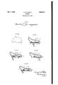
- Figure 1 shows a diagrammatic lay-out of a deaf-aid device incorporating the miniature receiver constructed according to the invention
- Figure 2 shows a perspective view of the receiver
- Figure 3 shows a sectional view of a receiver containing a piezo-electric crystal
- Figure 4- shows a corresponding view of a receiver containing an electro-magnetic vibrator
- Figures 5 and 6 show transverse sections showing alternative methods of mounting the piezo-electric crystal and the electro-magnetic vibrator, respectively.
- the miniature telephone receiver comprises a concavo-convex shell member, the convex surface I3 of which is so shaped as to fit snugly within at least the major concave portion of the pinna of the ear.
- the shell of the receiver I0 is hollow and contains an electro-acoustic transducer which may be of varied construction.
- a piezo-electric crystal I4 is mounted on suitable supports I5; IS in turn carried by the inner face of the shell and the crystal I 4 is coupled by a stud I! or the like to the outer convex member I3 of the shell.
- the crystal is connected in the usual manner by leads 20 to the amplifying device II.
- part only of the shell member I3 may form the diaphragm.
- the portion of the member I3 lying between the limits A, B disposed for example in the central region of the shell nearest the auditory meatus, may comprise the diaphragm proper and this portion may either be moulded integrally with the shell or may be suitably attached thereto.
- the piezo-electric crystal I4 is replaced by an electro-magnetic vibrator denoted generally by I8.
- I8 an electro-magnetic vibrator
- This comprises a core member I9 around which is wound a small coil 2
- Pole piece 22 is connected by a stud or the like IT to the convex member I3 of the shell.
- part only of the member I3 may form the diaphragm to which the mechanical vibrations are imparted.
- the shell member shown in Figure 3 may be formed of a lightweight material coming within the general class of plastics and may readily be moulded to the desired shape.
- the piezo-electric crystal may comprise for example a Rochelle salt crystal unit known to those skilled in the .art as a bender.
- the shell in the construction shown in Figure 4 may be formed of magnetic material so as to interact with the electrical transducer formed by the miniature electromagnet and pole piece system.
- a piezoelectric crystal i4 is secured at one end to the-re- V DC garagever shell it, which shell in this embodiment acts as a whole as a vibratory diaphragm.
- the piezo-electric crystal I 4 may be provided at its free end with a weight 23 which may be utilised for the control of frequency response.
- the electrical transducer consisting of the miniature electro-magnetic pole piece system is mounted directly on the receiver shell l0 and the vibrations of the pole piece 22 produced by the coil 2
- the construction of the telephone receiver ear plug in the formof a hollow shell makes it possibleto locate said receiver wholly within the major concave surface of the pinna of the ear.
- the'center of gravity of the receiver may be arranged to lie within the pinna of the ear so that any turning moment acting on the ear plug receiver tending to dislodge the same from its position within the pinna is considerably reduced.
- electro-acoustic transducer is described and shown as being disposed wholly within the interior of the shell member it is to be understood that the transducer may be disposed only partly within the interior cavity.
- An earphone adapted to be supported within the pinna of the ear comprising a closed casing shaped to conform to the pinna of the ear and including a vibratory wall which extends across the opening of the auditory meatus when the receiver is supported within the ear, and electrically operated means within said casing for vibrating said vibratory wall, the area of said vibratory wall being considerably larger than'the opening in th meatus of the ear.
- An earphone adapted to be supported within the pinnaof the ear comprising a casing shaped to conform .to the pinna of the ear and including a diaphragm wall which extends across the opening of the auditory meatus when the receiver is supported within the ear and is vibratory in a direction longitudinal of the meatus of the ear, and electrically operated means within said casing for vibrating said diaphragm wall, the vibratory area of said diaphragm wall being considerably larger than the opening in the meatus of the ear.
- An earphone'adapted to be supported'within the pinna of the ear comprising a concavo-convex shell member having its convex surfaceshaped to conform to at least the major concave portion of the pinna of the ear, said shell member being composed of moulded plastic material and having only part thereof constituting a vibratory diaphragm,and an electro-acoustic transducer disposed at least in part within the interior of said shell member and having a vibratory element connected to said diaphragm for vibrating same.
Description
N 9 c. M. R. BALBl 2,528,811
EARPHONE Filed March 23,- 1945 I Attorney Patented Nov. 7, 1950 EARPHONE Charles M. R. Balbi, London, England Application March 23, 1945, Serial No. 584,272-
In Great Britain April 1, 1944 This invention relates to telephone receivers and more particularly to a miniature telephone receiver or earphone of the kind which is supported within the pinna of the ear, as for example in the case of a telephone receiver forming part of what is generally termed a deaf-aid.
Miniature receivers of this kind have hitherto consisted of a. solid ear plug which is in general shaped to conform to the convolution of the pinna and the auditory meatus and which is provided with a passage extending therethrough so as to open into said meatus. In operation the air column within the passage of the ear plug is set in vibration by means such as an electromagnetic telephone unit which is supported on the external face of the plug.
The primary object of the present invention 'is to provide a telephone receiver of the above kind which is light in weight, is inconspicuous, is not readily dislodged by normal head movements, has no orifice which is subject to blockage due to wax and can be soaked in disinfectant and dried by wiping the surface with a clean rag.
A further object of the invention is to provide a miniature telephone receiver which is of simplified construction.
According to the present invention a telephone receiver of the above character includes a hollow shell member acting wholly or in part as a vibratory diaphragm.
The device of the inventionpreferably comprises a concavo-convex shell member having its convex surface shaped to conform to at least the major concave portion of the pinna of the ear and an electro-acoustic transducer disposed wholly or in part within the interior of the shell member and coupled to said shell.
The invention will be hereinafter more particularly described with reference to the accompanying drawing, in which:
Figure 1 shows a diagrammatic lay-out of a deaf-aid device incorporating the miniature receiver constructed according to the invention;
Figure 2 shows a perspective view of the receiver;
Figure 3 shows a sectional view of a receiver containing a piezo-electric crystal;
Figure 4-. shows a corresponding view of a receiver containing an electro-magnetic vibrator;
Figures 5 and 6 show transverse sections showing alternative methods of mounting the piezo-electric crystal and the electro-magnetic vibrator, respectively.
Referring to Figure 1, a miniature receiver 3 Claims. (01. 1'79107) denoted generally by I0 is connected to an amplifying device II which in turn is electrically connected to a transmitting microphone I2. The construction of the amplifier II and microphone I2 forms no part of the present invention and will not be more fully described herein.
. It is sufiicient to state that in accordance with normal practice acoustic vibrations impinging on the microphone diaphragm produce current oscillations from a battery forming part of the amplifier I I, which oscillations are amplified in said amplifier and are supplied through suitable electric conductors 20 connected to the vibrator unit of the receiver Ill.
As shown in Figure 2, the miniature telephone receiver comprises a concavo-convex shell member, the convex surface I3 of which is so shaped as to fit snugly within at least the major concave portion of the pinna of the ear. The shell of the receiver I0 is hollow and contains an electro-acoustic transducer which may be of varied construction.
As shown in Figure 3, which is a transverse section through the shell, a piezo-electric crystal I4 is mounted on suitable supports I5; IS in turn carried by the inner face of the shell and the crystal I 4 is coupled by a stud I! or the like to the outer convex member I3 of the shell. The crystal is connected in the usual manner by leads 20 to the amplifying device II.
In operation the vibrations produced by the crystal IA are transmitted through the stud I! to the convex member I 3 of the shell which thus acts as a vibratory diaphragm. In this manner sound waves are generated in the air column present in the auditory meatus of the wearer.
If desired part only of the shell member I3 may form the diaphragm. For example, the portion of the member I3 lying between the limits A, B disposed for example in the central region of the shell nearest the auditory meatus, may comprise the diaphragm proper and this portion may either be moulded integrally with the shell or may be suitably attached thereto.
In the embodiment shown in Figure 4 the piezo-electric crystal I4 is replaced by an electro-magnetic vibrator denoted generally by I8. This comprises a core member I9 around which is wound a small coil 2| while a vibrating pole piece 22 is disposed adjacent the core I9. Pole piece 22 is connected by a stud or the like IT to the convex member I3 of the shell. As in the embodiment shown in Figure 3, part only of the member I3 may form the diaphragm to which the mechanical vibrations are imparted.
The shell member shown in Figure 3 may be formed of a lightweight material coming within the general class of plastics and may readily be moulded to the desired shape. The piezo-electric crystal may comprise for example a Rochelle salt crystal unit known to those skilled in the .art as a bender. On the other hand the shell in the construction shown in Figure 4 may be formed of magnetic material so as to interact with the electrical transducer formed by the miniature electromagnet and pole piece system.
In the embodiment shown in Figure 5 a piezoelectric crystal i4 is secured at one end to the-re- V ceiver shell it, which shell in this embodiment acts as a whole as a vibratory diaphragm. If desired, the piezo-electric crystal I 4 may be provided at its free end with a weight 23 which may be utilised for the control of frequency response. In a similar manner in the embodiment shown in Figure 6 the electrical transducer consisting of the miniature electro-magnetic pole piece system is mounted directly on the receiver shell l0 and the vibrations of the pole piece 22 produced by the coil 2| mounted on the core 19 are transmitted to the shell as a whole, which shell itself acts as the vibratory diaphragm.
1 Y The construction of the telephone receiver ear plug in the formof a hollow shell makes it possibleto locate said receiver wholly within the major concave surface of the pinna of the ear. By the arrangement of the electro-acoustic transducer within the shell the'center of gravity of the receiver may be arranged to lie within the pinna of the ear so that any turning moment acting on the ear plug receiver tending to dislodge the same from its position within the pinna is considerably reduced.
While the electro-acoustic transducer is described and shown as being disposed wholly within the interior of the shell member it is to be understood that the transducer may be disposed only partly within the interior cavity.
It is pointed out that since the vibratory diaphragm is in contact with the pinna, said diaphragm is heavily damped and as a result any tendency for audio feed-backfrom the telephone receiver H] tothe microphone system 12 used in conjunction therewith is reduced to a minimum.
What I claim and desire to secure by Letters Patent is:
1. An earphone adapted to be supported within the pinna of the ear comprising a closed casing shaped to conform to the pinna of the ear and including a vibratory wall which extends across the opening of the auditory meatus when the receiver is supported within the ear, and electrically operated means within said casing for vibrating said vibratory wall, the area of said vibratory wall being considerably larger than'the opening in th meatus of the ear. v
2. An earphone adapted to be supported within the pinnaof the ear comprising a casing shaped to conform .to the pinna of the ear and including a diaphragm wall which extends across the opening of the auditory meatus when the receiver is supported within the ear and is vibratory in a direction longitudinal of the meatus of the ear, and electrically operated means within said casing for vibrating said diaphragm wall, the vibratory area of said diaphragm wall being considerably larger than the opening in the meatus of the ear.
3. An earphone'adapted to be supported'within the pinna of the ear comprising a concavo-convex shell member having its convex surfaceshaped to conform to at least the major concave portion of the pinna of the ear, said shell member being composed of moulded plastic material and having only part thereof constituting a vibratory diaphragm,and an electro-acoustic transducer disposed at least in part within the interior of said shell member and having a vibratory element connected to said diaphragm for vibrating same.
CHARLES M. R. BALBI.
REFERENCES. CITED The following references are of record in the file of this patent:
UNITED STATES PATENTS I Date Rutter an Jan. 1, 1946
Applications Claiming Priority (1)
| Application Number | Priority Date | Filing Date | Title |
|---|---|---|---|
| GB6123/44A GB581189A (en) | 1944-04-01 | 1944-04-01 | Improvements in or relating to telephone receivers |
Publications (1)
| Publication Number | Publication Date |
|---|---|
| US2528811A true US2528811A (en) | 1950-11-07 |
Family
ID=9808830
Family Applications (1)
| Application Number | Title | Priority Date | Filing Date |
|---|---|---|---|
| US584272A Expired - Lifetime US2528811A (en) | 1944-04-01 | 1945-03-23 | Earphone |
Country Status (2)
| Country | Link |
|---|---|
| US (1) | US2528811A (en) |
| GB (1) | GB581189A (en) |
Cited By (5)
| Publication number | Priority date | Publication date | Assignee | Title |
|---|---|---|---|---|
| US2874231A (en) * | 1955-12-02 | 1959-02-17 | Frank B Wallace | Ear mounted hearing aid device |
| FR2441983A1 (en) * | 1974-11-18 | 1980-06-13 | Hiroshi Ono | DEVICE FOR TRANSMITTING AND RECEIVING VOICE SOUNDS |
| WO2008145949A1 (en) * | 2007-05-31 | 2008-12-04 | New Transducers Limited | Audio apparatus |
| USD738862S1 (en) | 2013-10-25 | 2015-09-15 | Aliphcom | Ear piece |
| USD850417S1 (en) * | 2017-10-24 | 2019-06-04 | Shenzhen Ginto E-commerce Co., Limited | Ear hook |
Citations (8)
| Publication number | Priority date | Publication date | Assignee | Title |
|---|---|---|---|---|
| US1328620A (en) * | 1915-11-04 | 1920-01-20 | American Thermophone Company | Sounding-chamber for thermic telephones and other apparatus |
| US1630028A (en) * | 1925-01-15 | 1927-05-24 | De Elbert A Reynolds | Ear phone |
| US1733579A (en) * | 1926-12-24 | 1929-10-29 | Western Electric Co | Earpiece |
| US1893474A (en) * | 1931-05-27 | 1933-01-03 | Sonotone Corp | Earpiece for ear phones |
| US2045427A (en) * | 1933-05-24 | 1936-06-23 | Sonotone Corp | Bone-conduction hearing-aid |
| US2148477A (en) * | 1935-08-31 | 1939-02-28 | Dictograph Products Co Inc | Bone conduction audiphone |
| US2248837A (en) * | 1938-08-05 | 1941-07-08 | Mabel A E Walters | Custom-made hearing aid receiver tip |
| US2391924A (en) * | 1941-07-16 | 1946-01-01 | Brush Dev Co | Phone and method of making same |
-
1944
- 1944-04-01 GB GB6123/44A patent/GB581189A/en not_active Expired
-
1945
- 1945-03-23 US US584272A patent/US2528811A/en not_active Expired - Lifetime
Patent Citations (8)
| Publication number | Priority date | Publication date | Assignee | Title |
|---|---|---|---|---|
| US1328620A (en) * | 1915-11-04 | 1920-01-20 | American Thermophone Company | Sounding-chamber for thermic telephones and other apparatus |
| US1630028A (en) * | 1925-01-15 | 1927-05-24 | De Elbert A Reynolds | Ear phone |
| US1733579A (en) * | 1926-12-24 | 1929-10-29 | Western Electric Co | Earpiece |
| US1893474A (en) * | 1931-05-27 | 1933-01-03 | Sonotone Corp | Earpiece for ear phones |
| US2045427A (en) * | 1933-05-24 | 1936-06-23 | Sonotone Corp | Bone-conduction hearing-aid |
| US2148477A (en) * | 1935-08-31 | 1939-02-28 | Dictograph Products Co Inc | Bone conduction audiphone |
| US2248837A (en) * | 1938-08-05 | 1941-07-08 | Mabel A E Walters | Custom-made hearing aid receiver tip |
| US2391924A (en) * | 1941-07-16 | 1946-01-01 | Brush Dev Co | Phone and method of making same |
Cited By (9)
| Publication number | Priority date | Publication date | Assignee | Title |
|---|---|---|---|---|
| US2874231A (en) * | 1955-12-02 | 1959-02-17 | Frank B Wallace | Ear mounted hearing aid device |
| FR2441983A1 (en) * | 1974-11-18 | 1980-06-13 | Hiroshi Ono | DEVICE FOR TRANSMITTING AND RECEIVING VOICE SOUNDS |
| WO2008145949A1 (en) * | 2007-05-31 | 2008-12-04 | New Transducers Limited | Audio apparatus |
| US20120237075A1 (en) * | 2007-05-31 | 2012-09-20 | New Transducers Limited | Audio apparatus |
| CN101766036B (en) * | 2007-05-31 | 2014-07-02 | 新型转换器有限公司 | Audio apparatus |
| US8842870B2 (en) * | 2007-05-31 | 2014-09-23 | Nvf Tech Ltd. | Audio apparatus |
| US20150071479A1 (en) * | 2007-05-31 | 2015-03-12 | Nvf Tech Ltd. | Audio Apparatus |
| USD738862S1 (en) | 2013-10-25 | 2015-09-15 | Aliphcom | Ear piece |
| USD850417S1 (en) * | 2017-10-24 | 2019-06-04 | Shenzhen Ginto E-commerce Co., Limited | Ear hook |
Also Published As
| Publication number | Publication date |
|---|---|
| GB581189A (en) | 1946-10-03 |
Similar Documents
| Publication | Publication Date | Title |
|---|---|---|
| US2971065A (en) | Ear insert hearing aid | |
| US5949896A (en) | Earphone | |
| EP0455203B1 (en) | Dual outlet passage hearing aid transducer | |
| US4843628A (en) | Inertial microphone/receiver with extended frequency response | |
| US2148477A (en) | Bone conduction audiphone | |
| US2938083A (en) | Transistor amplifier hearing aid unit with receiver vibration feedback suppression | |
| US3448224A (en) | Rigid in-the-ear hearing aid | |
| WO2019109389A1 (en) | Noise reduction earmuffs | |
| KR101863540B1 (en) | Diaphragm for protecting of eardrum | |
| US3030455A (en) | Bone-conduction all-in-one transistor amplifier hearing aid | |
| US2528811A (en) | Earphone | |
| JPH04227396A (en) | Headphone | |
| US2400281A (en) | Electromechanical signal translating apparatus | |
| US3030456A (en) | Bone-conduction all-in-one transistor amplifier hearing aid | |
| US2496483A (en) | Loud-speaker with diaphragm an integral part of outer casing | |
| US2832842A (en) | Body contacting inertia reaction electromechanical transducing devices | |
| JP6421360B2 (en) | Inner earphone | |
| KR20110010033A (en) | A ear phone of bone conduction | |
| US2327136A (en) | Hearing aid microphone | |
| US2820107A (en) | Electro-mechanical signal transducers | |
| US3423544A (en) | Electroacoustic bone conduction receiver | |
| EP0437323B1 (en) | Hearing aid | |
| EP3788795B1 (en) | An electroacoustic earcup for open-back headphones | |
| KR101583650B1 (en) | nonflammables speaker of piezo electricity type | |
| US2552800A (en) | Magnetic microphone |