US2528427A - Record feeding device - Google Patents
Record feeding device Download PDFInfo
- Publication number
- US2528427A US2528427A US32568A US3256848A US2528427A US 2528427 A US2528427 A US 2528427A US 32568 A US32568 A US 32568A US 3256848 A US3256848 A US 3256848A US 2528427 A US2528427 A US 2528427A
- Authority
- US
- United States
- Prior art keywords
- lever
- record
- shaft
- plate
- heading
- Prior art date
- Legal status (The legal status is an assumption and is not a legal conclusion. Google has not performed a legal analysis and makes no representation as to the accuracy of the status listed.)
- Expired - Lifetime
Links
Images


Classifications
-
- G—PHYSICS
- G06—COMPUTING OR CALCULATING; COUNTING
- G06K—GRAPHICAL DATA READING; PRESENTATION OF DATA; RECORD CARRIERS; HANDLING RECORD CARRIERS
- G06K15/00—Arrangements for producing a permanent visual presentation of the output data, e.g. computer output printers
- G06K15/02—Arrangements for producing a permanent visual presentation of the output data, e.g. computer output printers using printers
- G06K15/04—Arrangements for producing a permanent visual presentation of the output data, e.g. computer output printers using printers by rack-type printers
-
- B—PERFORMING OPERATIONS; TRANSPORTING
- B41—PRINTING; LINING MACHINES; TYPEWRITERS; STAMPS
- B41J—TYPEWRITERS; SELECTIVE PRINTING MECHANISMS, i.e. MECHANISMS PRINTING OTHERWISE THAN FROM A FORME; CORRECTION OF TYPOGRAPHICAL ERRORS
- B41J11/00—Devices or arrangements of selective printing mechanisms, e.g. ink-jet printers or thermal printers, for supporting or handling copy material in sheet or web form
- B41J11/36—Blanking or long feeds; Feeding to a particular line, e.g. by rotation of platen or feed roller
- B41J11/42—Controlling printing material conveyance for accurate alignment of the printing material with the printhead; Print registering
Definitions
- This invention relatesjgenerally to improved-f record feeding devices ana more particularly to automatic means for'skip'pinig selected spaces of a plurality of heading 'spacesunde'r' control of machine control records?
- the main purpose is to.
- said space being relatedto aeertain-heading card that is to control printing in that space.
- An object of the invention'isto provide means for automatically printing in, or skipping over any Of a plurality of heading spaces which are blocked off at the top of each form one, preprinted continuous recordstrip.
- the device iscontrolled by record cards arranged in groups of related heading and detail cards; the'heading' cards of a group being further subdivided intoa plurality of heading sets, each set bearing datafor'separate identification such as that of a buyer, retailer or wholesaler, and instructions such as shipping instructions.
- the purpose is to skip those heading areas devoted to certain classes of heading data when the relatedcards are missing. There is also a requirement toskip all headingareas when there is an overflow of items ordetail data from the bottom of one bill to the top of the body area of the next bill form, 1. e., when the number of data lines in the body area is not suflicient for the number of related detail records.
- Another object of the invention is to provide electrical devices under joint control of heading cards and an automatic carriage for jfeeding record material with line space skipping operations between and over headingareas on forms onsaid material.
- Relay devioesfaref provided and controlled according' to the presence"or absence of heading cardsand the' chan'geffrom heading to detail cards.
- Other relay devices cooperate therewith “and 1 time “the successive onseriatirn reactivations of the line space devices to advance the out in the following descriptiddahd claims and illustrated in” the accompanyin drawings; which disclose, by way of example,gthe principle fof the invention and the best mode, 'which'has bee'nicontemplated of applying thatfpi i "Inthe drawings: Fig. l'shows a series of perforated ma d? cards "related t9 e first two group of :a series of accounts. r l
- Fig. 2 shows an example o of a'record strip printed und first and second groups of cards show Fig. 3 shows a portion or fthe control record as it is perforated incode to represent thevariousdigit and alphabet data.
- j 1" Fig. 4 is a sectional elevation viewshojwing the numeral and alphabet printing mechanism;
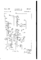
- Fig. 5 is an elevation viewof thev line spac control mechanism.
- Fig. 6 is an elevation view of themechanism settable to predetermine thespacing of items and the overflow line or the" record forms.
- Fig. 7 is a detail perspective'view; of theheading space tripping cam devicesior controlling the spacing of the headings on the record forms.
- Flg fl is an elevation viewof the mechanism g for controlling ejection for moving the record strip fromiorm to form with along feeding operation.
- Figs. 9a-9i whentaken together form a wiring diagram of pertinent portions of the tabulating machine and automatic carriag'egwith the special control wiring shown in heavy lines.
- the feeding controls are illustrated in coordination with a record controlled.alphabet-printing tabulator.
- the printing machine isior thekind shown in Patents Nos. 2,079,418 and -2,l11 ,1;22-and application Serial No..-609,85 4,,.filed.on August 9,
- control is exercised by a sequenceoi' record cards arranged to print alphabetic;.headingqdata such as names, addresses, dates;inrcombinationhwith other detail cards perforatedltoz' represent items and amounts to .be -,recorded, iaccumulated. totalled and charged. to the avario'us customers.
- the cards there represented are used 'to control the printingon two successivexiorms, suc'h'as those C: recorded above a number or-"detall or body lines D.
- On the second form is an invoice to a different customer, which includes onl the heading lines A2 and C2, but no hea'ding'lines corresponding to B" of the first form, because the goods are not to be shipped to a different address.
- the record strip R (Fig. 2) is a continuous record divided into forms and preprinted with blocked-off areas for headings, shipping instructions, detail numbers, identifications and price columns. This is merely illustrative of the control for space skipping which is useful for many kinds of printed records.
- the diagrammatic record card CA has the usual perforations for indicating numerical values as shown att he left side of the card.
- the alphabetical characters from A to I are combinations of one of the numerical characters from 9 to 1, plus a perforation in the R index point position.
- the characters J to R each comprise edge held down by a bar.
- Fig. 4 is shown an alphabet type bar T which is provided with a plurality of type elements upon which the digit and alphabet characters are arranged as indicated.
- the various characters are arranged and labeled in accordance with a particular zone.
- the digits are included in zone I; the letters StoZinzone2; JtoRinzone 3; andAtoIin zone 4.
- Reference to Fig. 3 reveals that the letters I, R and Z each contain a perforation in the 9 index point position, but has a different zone perforation R, X and 0.
- the letters H, Q and Y each contain the perforation t and a drierrent zone perforation.
- the type bar T is arranged to be moved to pass the printing position opposite platen P in synchronism with the movement of the card past the lower brushes and, as the 9 index point positions traverse the brushes, the Z type element will be approaching the printing positions; as the 8 index point positions traverse the brushes, the Y type element will be approaching the printing position, and so on.
- Each type bar T is provided with a series of teeth II'I which are labeled 9 to II and which represent corresponding index point positions on the record card. As the type bar is moved upwardly the teeth III move to pass a stopping element H8.
- the element Ill is pivoted at I25 to a bell crank I26 which is normally held in the position shown by a bell crank latch I21 which has connection through a link I28 to the pivoted armature I29 of print control magnet PR.
- the element H8 may be stopped by a lever Ill which loosely straddles a rod and has its upper curved 4
- the left end of the lever has an extension I22 resting upon a bail I33 which occupies a raised position during the analysis of the digit representing positions of the card.
- the member I2I is provided with three teeth which, under control of the bail I", move downwardly to pass the toe of a stopping pawl I29 during the time that the zone perforations II, X and R pass thebrush LB.
- the pawl III is normally held with its toe out of the path of the teeth by a bell crank latch I which has a are passing the brushes the bail I48 is rocked slightly counterclockwise so that an energizatlon of magnet PR, due to the sensing of a zone perforation, will rock its armature I41 clockwise to elevate link I46 and rock bell crank I40 counterclockwise to release pawl I39 which will engage the first tooth if the zone hole is at the zero position; the second tooth X, if it is in the X index position; or the third tooth R if it is an R hole. If no zone hole is present, the lever I3I will rock an additional step to cause. an upper shoulder to engage the pawl I39. From the foregoing it is apparent that the alphabet printing bars can be stopped as governed by the address code perforations on the name and address cards, so that various words are spelled and recorded at the printing line.
- the platen P has the usual pressure rollers cooperating therewith to hold and advance the record sheet R as the platen is rotated.
- a bracket I (Fig. 8) projecting from the carriage frame I34, forms a bearing for the shaft I42 of the carriage motor CM.
- a pinion I43 on the motor shaft I42 meshes with a gear I44 pivoted on a stud I45 on the side of bracket I4I.
- Attached to gear I44 is a smaller gear I35 in mesh with a gear I36 keyed on the shaft I31.
- the side of gear I86 (Fig. is secured a gear 93 in mesh with an idler gear 94.
- the driving train of connections continues through gear 94 meshing with another idler gear 95 which in turn drives a gear 96 fastened to the line spacing drive shaft I5I.
- the gear connections just traced form a constantly running train from motor shaft I42 to line spacing drive shaft I5I.
- Other gearing also outside the frame I34 with the line space drive, forms a selective two-speed drive for the ejection mechanism described hereinafter.
- shaft I5I carries a clutch plate I52 attached thereto. Adjacent the toothed plate I52 is a cam I54 loosely pivoted on shaft. I5I. This cam carries a clutching pawl I55 pivoted at I56.
- a compression spring I58 mounted in a stud on cam I54 tends to engage pawl I55 with clutch plate I52, but an extending tail on the pawl is normally obstructed by the end of anarmature lever I60 connected to the armature I6I of a line spacing control magnet ISM.
- the lever I60 is pivoted on a stud I62 and is urged in a counterclockwise direction against stop pin I63 by a spring I64.
- link I12 is pivotally connected at I14 to a line spacing plate I15 loosely mounted on the platen feed and line space shaft I16.
- the plate I16 carries a feed pawl I11 pivoted at I18 on the plate and adapted to cooperate with a ratchet sear I19 fixed to shaft I16.
- This shaft is secured to a gear I01 (Fig. 6) and is thereby adapted to turn the platen P through gear I08 and gear I09 fastened to the platen shaft 69.
- link I12 is brought about by means of a manipulated arm I83 extending inside the carriage frame I34.
- the arm is connected to an outside knob with a plunger which the operator may set to hold the arm in any one of three positions identified on the side of the frame.
- a shaft I82 is connected to the outside knob and has secured thereon arm I83 with a tab I84 cooperating with the side of link I12.
- a spring I86 urges the lever I68 in a counterclockwise direction and tends to hold roller I69 against cam I54.
- Link I12 is held in constant cooperation with tab I84 by means of a spring 64.
- a spring I81 wound around stud I18 tends to move pawl I11 into cooperation with ratchet I19.
- a cam face on the lower portion of pawl I11 cooperates with a stud I89 projecting from the frame I34 in such manner that the pawl is forced away from the ratchet.
- the same stud I86 serves as a stop for the plate I15 when it is drawn to the home position by a spring I89.
- ratchet I19 Secured to the side of ratchet I19 is a star wheel I90 provided for the purpose of normally preventing backward movement of the platen drive shaft I16.
- a pawl I9I loosely pivoted on shaft I92 and held into cooperation with the star wheel by spring I93.
- gears I44, I35, I36. 93,94, 95, and 96 (Figs. 5 and 8) are used in ejecting as well as in line spacing.
- Attached to gear 96 (Fig. 5) is a gear 65 meshing with a gear 66 keyed to a shaft 61.
- This shaft 61 is similar to the other shaft I31 (Fig. 8) in that it may be moved axially to place a pinion 81 thereon in and out of mesh with an eject drive gear 68.
- the other shaft I31 terminates in a similar pinion 8,8.
- Shaft I31 operates at a higher rate of speed than shaft 61,
- the ejection driving connections continue through a clutch which may be connected at any time in'the operation of the machine to cause a form ejection operation.
- the driving member of the clutch is the gear 99 driven by either of the pinions 81 or 89, previously mentioned.
- gear 58 is pivoted on stud "I in frame I24 and carries attached thereto a toothed clutch plate I91. Loosely pivoted on the same stud I'll is an ejection cam plate 200.
- Ejection is initiated by energization of magnet EM to feed the strip from form to form after line spacing operation has brought about an overflow condition, or when a group change and total printing operation calls for another blank form.
- Fig. 6 the ejecting devices are shown in the normal position.
- a link 2I9 is articulated at 2 on side of plate 209 and at the other end it is pivotally connected at 2I2 to side of an ejecting frame 2I2 (Fig. 8) pivoted at 209 on the frame of the control unit.
- This rocking eject frame 2I3 is formed in the shape of an arc and carries a similarly shaped plate 241 with a series of teeth 2 cut in the inner side of the arc.
- a block 2 I5 formed with a single tooth 2I9 adapted to ratchet over the teeth 2 and engage any one of the teeth as a link 2" carrying the block 2l5 is drawn along the inner surface of the arc during line spacing operation.
- the block 2I5 is loosely pivoted on link 2I1 by means of a stud 2I8 mounted on link 2I1.
- the return stroke of sector 220 may be adjustably varied to determine the length of form to be printed in the machine.
- the form may be shortened by stopping the sector 220 at any point along its travel counterclockwise towards the left (Fig. 6)
- a lever 259, pivoted on shaft 22I carries a stopping block 492 cooperating with a stud 260 mounted on the side of sector 220.
- LIhe upper end of the form length-setting lever 259 is adapted to be adjusted around and held in any position along an are formed by a segmental index plate This index plate is secured at 264 to a frame'plate 262 which is held to casting I34 by screws 269. and at the other end the index plate encircles shaft 285.
- the surface of the index plate is inscribed with long lines representing inches of spacing, and short lines (not shown) representing lines of print spacing.
- a pointer 265 is formed on the end of lever 259 opposite a gripping plate 491 to indicate. the length of sheet selected.
- the bottom edge of plate 2" is formed with rack teeth 241 which are engaged by a key in the shape of a pinion that is inserted in aperture 495 and turned to move lever 259 and sector 220 to a selected position against the pressure of spring 242 (Fig. 8).
- the lever when the selected position is reached, the lever may be locked in place by turning a nut 496 (Fig. 6) on a screw passing through the gripping plate. corrugations on plate 26I and lever 259 lock the lever in place when plate 491 is drawn towards lever 259 to pinch index plate 2 therebetween. As shown in Fig. 6 the lever 259 and sector 22') are positioned to handle forms five and one-third inches in length.
- a series of contacts are employed to control the ejection and line space magnets and the tabulating start and stop devices. These contacts are supported on the inside of the casing I34.
- a channel bar 595 supports three blocks 595, 591 and 598 each holding a pair of contacts.
- the channel is secured asses a7 to casting I34 and formed to hold stud 698 and shafts 6H) and H supporting the operatin members for the contacts.
- the machine is provided with devices for skipping a variable amount of space between the last address line of a heading and the next heading or the number printing line for the first item. It is described hereinafter how the line spacing magnet LSM is energized to start the skippingoperation. After feeding a selected length of strip, space skipping is stopped by opening contacts 498 (Fig. 6) with devices about to be described.
- the skip stop contact 488 is held closed by a bell crank 5l2 fastened to shaft Bill.
- the crank in turn is held by a latch 6l3 pivoted on shaft 265 and formed with a shoulder engaging a lug 514 on the crank.
- a flipper 6i6 (Fig. '7) on a stud H6.
- the latch is operated by an adjustable tripping lever 5i1 fastened to an arcuate slotted plate 618 (Fig. 6') secured to the sector 228.
- the upper'end of the lever 6 (Fig. 7) is formed with a pointed cam face d which, together with auxiliary cam points b and c, cooperate with flipper SIS to rock the latch and release the bell crank 6l2.
- a pointer 6i9 on the lever 6" maybe set to the proper point along scale 26i so that the first item line D may be printed at any selected line of the forms on the strips -A screw and nut connection extending through lever 6H and a slot 521 in plate 5l8 may be moved along the slot and fastened in the desired position.
- the ejecting operation iscontrolled by the energization of magnet EM.
- This magnet is energized at various times according to the setting of the controls and the closing of contacts to form a completed circuit.
- the contacts 269 (Fig. 6) are closed as the printing on the record approaches the end of a form.
- These contacts 269 are operated by an insulation finger 218 fastened to one end of a lever 21i pivoted on stud 599.
- the other end of the lever is formed with a lug 212 engaged by a latch 213 pivoted on shaft 265 alongside latch 5l3.
- Latch 213 is operated at a selected point in the feeding of a record form, by a cam face on the upper end of a lever 214 loosely pivoted on shaft 22! and held in place by a nut and screw projecting through slot 62L
- a pointer 526 on the lever indicates the inches of space through which the record form is linespaced before contact operation takes place.
- contacts 488 are present setting is at. four and one-half inches, equivalent to twenty-seven line spaces.
- the lever'21i is restored by a link 216 con-- nected thereto by aspin and slot formation 211.
- a contact operating lever 218 pivoted at 280 on a 'flxed plate I38 and drawn by a spring 28i into contact with the periphery of the cam plate.
- the upper end of the lever 219 is formed with aproiection 282 which acts as a cam face and also as a latch in cooperating with a notch 283 out in the periphery of plate 280.
- aproiection 282 acts as a cam face and also as a latch in cooperating with a notch 283 out in the periphery of plate 280.
- the side of notch 283 acts as a cam face to rock lever 218 in a clockwise direction, moving down an arm- 284 connected thereto by pin and slot connection 286.
- the arm is fastened to one end of shaft *5, the other end of which carries a member 281 with an insulation finger 288 for opening and closing contacts 286 and 291.
- cam lever 218 serves to open contacts 286, but contacts 28i are closed later in the operation when a projection 288 on cam plate 280 strikes the end 282 of the lever,
- lever in determines the position in which line space skipping is terminated and item printing is initiated, and then after a series of printing and line spacing operations, the other lever 214 comes into action to determine the length of the printing area desired, after which ejection is to be initiated to the first heading line determined by the setting of pointer 266.
- an auxiliary stopping means or cam plate 508 (Fig.
Landscapes
- Engineering & Computer Science (AREA)
- General Engineering & Computer Science (AREA)
- Physics & Mathematics (AREA)
- General Physics & Mathematics (AREA)
- Theoretical Computer Science (AREA)
- Handling Of Sheets (AREA)
Description
Filed June 12, 1948 J. E. DAYGER ETAL RECORD FEEDING DEVICE 15 Sheets-Sheet 2 oI' "n :6
I 1 l f REPREQENTATEVE INVOICE E? CITY, STATE :22; :8 g} E RANK A JONES I 1 136 BROADWAY I LNEWYORK NY J VIE ATE lg W I 01 FBROWNES HARDWARE STORE 3/ I0 03 46 {o O} C MO- DAY YEAR :0
I L D I O E SHIPPING INSTRUCTIONS TERM rmmmm: O TRUCK PREPAID 2z IODAY'S 222/ 8072 9 23 IO 01 VIA SMITH NET 30 go 0 QUANTITY UNIT DESCRIPTION STOCK NO. PRICE AMOUNT 0 I I 17 0oz RAKE BAMBOO 3605 I176 199 92 o 0oz HOSE GARDEN 3302 as 00 1260 00 E8 1 2 0oz SHOVEL COM 5706 46 32 55s 84 IO i 12 0oz SHOVEL sNOw 1102 53 76 64512 I 85 2a PKG SANDPAPER 6 BY 6 4107 250 70 00 I8 I BOX BULBS I00 WATTS 1105 180 45 00 IO i 500 YD OIL CLOTH 34 IN 2106 90 00 l o, O A 2865 88 IO 01' {O 11225122521 -o1- 1-0- I I OI IO 5 I PANY INVOICE EC) 0: SOLD I CIT STQTE 1347 2 i o WILLIAM B SMITH I 0; I446 CAMP 5T L/ I J INVO CE DATE I I0 02 46 i O: c, 5 MO- DAY YEAR O 0' D '0 Q E S$PRPILI)IE RJSTQLi CEZPOBIASE D Z VT E EDQS 7S ALE$Af2fg8 cus'r.5Rio.1N;. CUSLORDEQA: m5; go vIA JONES NET 30 O O QUANTITY UN T DESCRIPTION STOCK NO. PRICE AMQUNT o O O f Box TACKS THUR/I0 4100 I 20 42 00 g 0: I2 002 SPRINKLERS 360A 3120 37A f lEQ Q A.
I 5 0oz RAKE STE"L 2110 I INVENIORS OI r r E LEOAY'OER o: 7 J9 Z SHQVELS :1 BY O.B.sI-IAEER Aw TAEI a I134 ATTORNEY J. E. DAYGER ET AL RECORD FEEDING DEVICE Filed June 12, 1948 Milling 15 Sheets-Sheet 3 HNVENTORS J. E. was ER m w. SHAFER RN EV Oct. 31, 195% J. E. DAYGER HAL 15 9 RECORD FEEDING DEVICE Filed June 12, 1948 15 Sheets-Sheet 4 ENVENTORS JE. DAYGER W OB. SHAFER @dn 3% fi fl J, DAYGER HAL 2 5223 4 12? RECORD FEEDING DEVICE Filed June 12, 1948 3.5 Sheets-Sheet 5 INVENTORS J.E. DAYC-ER Y OBSHAFER j. kmmwz:
ATTORNEY mi, 2533,, mm J. E. DAYGER ETAL RECORD FEEDING DEVICE l5 Sheets-Sheet 6 Filqd June 12, 1948 mvzm'oms J E. DAYGER {F d ATTORNEY @mo 3L 195%) J. E. DAYGER ETAL RECORD FEEDING DEVICE 15 Sheeis-Sheei: 8
Filed June 12, 1946 BY 0. av SHAPE R Q- ATTORNEY mm m H Get, 31, W50 J. E. DAYGER EFAL RECORD FEEDING DEVICE l5 Sheets-Sheet 9 Filed June 12, 1948 F l [:13 Ml. MIT/1M 6245; 7am WK 0M4 (J? M [m WA W 3 u #Wa W i d m M 5 PW 0A.
mvmwowsi E. DAYGE R J. O. B. SHAFER ATTORNEY m 331, 39% J. E. DAYfiER HAL RECORD FEEDING DEVIGE l5 Sheets-Sheet 10 Filed June; 12, 19 18 EJECT I J. E. DAYGE 0 SHAFER ATTCRNE l5 Sheets-Shem 11 J. E. DANGER mm.
RECORD moms DEVICE M w w mum w @A in, m mm 5 f 111.: 4N3! NWAH 0W EFZ W1 m was 0 W) 6 N L g A J J W H M W EDD M W W 7 o WM a n@ 5 .v E W wlllWllJ W 4 w W? W 2% Y W W W WW W H a 5 w g F W a 5 f n W 6) o E a y lzLllu 4 Z W 3 d 0 cm W PPM/IF w WA @A rib E v 7! I l 7 W W 5 MW 0 a Q m z a M ilk @j z r J W v w M MW 0 W m r (g V G F F v P w p W D WM M Q M a 6 0n m w 4 D w P \L f m WM 2 5 M. a H 9 w m j" MM w s 3 4 1 4 1 w w afii EL WE H 7 L W wVm A.
Uzi BL 39% Filed June; 12, 1948 2.31? 1&7,
ATTORNEY l5 Shams-Sheet 112 J. E. DAYQE ETAL RECORD FEEDING DEVICE ATTORNEY WVENTORS' J. E Dl-WGER Ov E SHAFER Filed June 12, 1948 HI. IA? MAN.
15 Sheets-Sheet l3 54W A072 smer 1W J. E. DAYGER mm.
RECORD FEEDING DEVICE Dan-31 mm Filed June 12, 1948 ii/EC? a Fr/M STOP INVENTORS E DAYGER B. SHAFER ATTORNEY 15 Sheets-Sheet 14 J. E. DAYGER ETAL RECORD FEEDING DEVICE INVENTORS I J. E. DAYC-ER O B SHAFER MK ATTORNEY Get. 3B,, 315
Filed June 12, 1948 mm -52; f
Ottft.a 3% 1950) U YG AL 2,528
RECORD FEEDING DEVICE.
Filed June 1948 15 Sheets-Sheet 15 6315 v 5 55,497 310; C6); (52 a l 04 I 1. tl 19 Q yaw 4% ,5; IL F7 MM W ' ENVENTQRS '59/ a 752E m Patented Oct. '31,
This invention relatesjgenerally to improved-f record feeding devices ana more particularly to automatic means for'skip'pinig selected spaces of a plurality of heading 'spacesunde'r' control of machine control records? The main purpose is to.
so space a record form as to present at'theprinting line a certain one'of-severalheadingspaces,
said space being relatedto aeertain-heading card that is to control printing in that space".
An object of the invention'isto provide means for automatically printing in, or skipping over any Of a plurality of heading spaces which are blocked off at the top of each form one, preprinted continuous recordstrip. The device iscontrolled by record cards arranged in groups of related heading and detail cards; the'heading' cards of a group being further subdivided intoa plurality of heading sets, each set bearing datafor'separate identification such as that of a buyer, retailer or wholesaler, and instructions such as shipping instructions. The purpose is to skip those heading areas devoted to certain classes of heading data when the relatedcards are missing. There is also a requirement toskip all headingareas when there is an overflow of items ordetail data from the bottom of one bill to the top of the body area of the next bill form, 1. e., when the number of data lines in the body area is not suflicient for the number of related detail records.
Another object of the invention is to provide electrical devices under joint control of heading cards and an automatic carriage for jfeeding record material with line space skipping operations between and over headingareas on forms onsaid material. Relay devioesfarefprovided and controlled according' to the presence"or absence of heading cardsand the' chan'geffrom heading to detail cards. Other relay devices cooperate therewith "and 1 time "the successive onseriatirn reactivations of the line space devices to advance the out in the following descriptiddahd claims and illustrated in" the accompanyin drawings; which disclose, by way of example,gthe principle fof the invention and the best mode, 'which'has bee'nicontemplated of applying thatfpi i "Inthe drawings: Fig. l'shows a series of perforated ma d? cards "related t9 e first two group of :a series of accounts. r l
Fig. 2 shows an example o of a'record strip printed und first and second groups of cards show Fig. 3 shows a portion or fthe control record as it is perforated incode to represent thevariousdigit and alphabet data. j 1" Fig. 4 is a sectional elevation viewshojwing the numeral and alphabet printing mechanism;
Fig. 5 is an elevation viewof thev line spac control mechanism. V
Fig. 6 is an elevation view of themechanism settable to predetermine thespacing of items and the overflow line or the" record forms.
Fig. 7 is a detail perspective'view; of theheading space tripping cam devicesior controlling the spacing of the headings on the record forms.
. Flg fl is an elevation viewof the mechanism g for controlling ejection for moving the record strip fromiorm to form with along feeding operation.
Figs. 9a-9i whentaken together form a wiring diagram of pertinent portions of the tabulating machine and automatic carriag'egwith the special control wiring shown in heavy lines.
, The feeding controls are illustrated in coordination with a record controlled.alphabet-printing tabulator. ,The printing machine isior thekind shown in Patents Nos. 2,079,418 and -2,l11 ,1;22-and application Serial No..-609,85 4,,.filed.on August 9,
record sheetto jump over one" or more heading spaces. -'Mechanical means are provided to break the line spacing control circuit-at a plurality of heading start lines, but these breaks are shunted selectively and successively'by the relays for detecting the absence 'of heading card groups.
is to automatically. carry on the following opera- 1 ,Such a sequence ofcardsj.;is.showmin Figrl and Patent No.2,189,025. I
1945, wherein mechanisms are shownfor feeding record cards one by one and analyzing thecards electrically tocontrol the setting or type 5 bars and the accumulation of amounts and total printing of such amounts. 'I'heautomaticstrip feeds a r a is f h kindidescribed in detail in In the printing of bills onaicontinuous strip.
control is exercised by a sequenceoi' record cards arranged to print alphabetic;.headingqdata such as names, addresses, dates;inrcombinationhwith other detail cards perforatedltoz' represent items and amounts to .be -,recorded, iaccumulated. totalled and charged. to the avario'us customers.
the cards there represented are used 'to control the printingon two successivexiorms, suc'h'as those C: recorded above a number or-"detall or body lines D. On the second form is an invoice to a different customer, which includes onl the heading lines A2 and C2, but no hea'ding'lines corresponding to B" of the first form, because the goods are not to be shipped to a different address.
Referring back to the cards in Fig. 1 and reading them from the bottom to the top, it is noted 'tinction between the different sets of the heading data cards, other differently located '2! perforations I2 are'punched in the last card of each of the heading sets A, B and C. It is also noted that the second or B heading set of cards of the first group is further identifiedby the X punchings II which are used to forestall skippingof the B space on the record strip R. There are no B-set cards in the second group and this is reflected in the blank space on the second form in Fig. 2. These set identifying perforations I I and I2 are used to select the various carriage stopping and starting controls for determining the position of the record R and properly locating the first line of each series of heading impressions.
There is further record feeding control provided in the form of X detecting devices for sensing the change from cards having heading perl'orations III to those following detail cards 9 lacking such identification. Upon such a change of X to no X cards, the record form is advanced to 1 the position in the body of form which is designated to receive the first item impression. Thereafter, when the detail records are controlling for recording, ,the record form is advanced in line spacing. I
There is a further distinction between the various cards in a sequence related to more than one account. Group number perforations are used to distinguish between the cards relating to different customers, Therefore, upon the passage of the last detail card 9 and advancement of the first heading card of the incoming group # 2, there is detected a change in the group numbers and the machine is controlled to take a total and record the total on a predetermined total line. After the total is printed, long feeding ejection is initiated and limited by the setting of the carriage lever to carry the record strip over into position to record the first heading line on the third form.
The record strip R (Fig. 2) is a continuous record divided into forms and preprinted with blocked-off areas for headings, shipping instructions, detail numbers, identifications and price columns. This is merely illustrative of the control for space skipping which is useful for many kinds of printed records.
The heading name and address cards l-l (Fig.
'1) bear alphabet indicia in the form of code perforations. These perforations are sensed by the lower brushes of the tabulator and directed into print control magnets to control the recording of names and addresses.
The code arrangement of the perforations in the record card will first be explained. Referring to Fig. 3, the diagrammatic record card CA has the usual perforations for indicating numerical values as shown att he left side of the card. The alphabetical characters from A to I are combinations of one of the numerical characters from 9 to 1, plus a perforation in the R index point position. The characters J to R each comprise edge held down by a bar.
a perforation in one of the numerical positions 9 to 1, plus a perforation in the X index point position. The remaining letters of the alphabet, namely S to Z, each comprise a combination including one of the perforations 9 to 2, plus a perforation in the 0 index point position.
It may be mentioned that, as the address cards pass under the lower brushes and differentially timed impulses are initiated, these impulses are carried to control magnets and used to position alphabet print bars as about to be explained with reference to mechanism similar to that shown in Patent No. 2,111,122.
In Fig. 4 is shown an alphabet type bar T which is provided with a plurality of type elements upon which the digit and alphabet characters are arranged as indicated. For the purposes of explanation, the various characters are arranged and labeled in accordance with a particular zone. Thus, the digits are included in zone I; the letters StoZinzone2; JtoRinzone 3; andAtoIin zone 4. Reference to Fig. 3 reveals that the letters I, R and Z each contain a perforation in the 9 index point position, but has a different zone perforation R, X and 0. Similarly, the letters H, Q and Y each contain the perforation t and a diilerent zone perforation.
The type bar T is arranged to be moved to pass the printing position opposite platen P in synchronism with the movement of the card past the lower brushes and, as the 9 index point positions traverse the brushes, the Z type element will be approaching the printing positions; as the 8 index point positions traverse the brushes, the Y type element will be approaching the printing position, and so on.
Each type bar T is provided with a series of teeth II'I which are labeled 9 to II and which represent corresponding index point positions on the record card. As the type bar is moved upwardly the teeth III move to pass a stopping element H8. The element Ill is pivoted at I25 to a bell crank I26 which is normally held in the position shown by a bell crank latch I21 which has connection through a link I28 to the pivoted armature I29 of print control magnet PR.
Upon the energization of magnet PR in response to the sensing of a digit perforation, armature I29 will be rocked clockwise, drawing downwardly on link I22 to cause clockwise rocking of latch I21 to release bell crank I26 whose 'spring will thereupon shift the stopping element III toward the right into the path of the tooth III corresponding to the perforation whose sensing caused energization of the magnet. Further upward movement of the type bar is thus interrupted at this time. The stopping element III is held against upward movement by a bail I" which later, as the zone holes are sensed, rocks counterclockwise to permit resumption of the upward movement of the type bar. During such movement, the element H8 may be stopped by a lever Ill which loosely straddles a rod and has its upper curved 4 The left end of the lever has an extension I22 resting upon a bail I33 which occupies a raised position during the analysis of the digit representing positions of the card. The member I2I is provided with three teeth which, under control of the bail I", move downwardly to pass the toe of a stopping pawl I29 during the time that the zone perforations II, X and R pass thebrush LB. The pawl III is normally held with its toe out of the path of the teeth by a bell crank latch I which has a are passing the brushes the bail I48 is rocked slightly counterclockwise so that an energizatlon of magnet PR, due to the sensing of a zone perforation, will rock its armature I41 clockwise to elevate link I46 and rock bell crank I40 counterclockwise to release pawl I39 which will engage the first tooth if the zone hole is at the zero position; the second tooth X, if it is in the X index position; or the third tooth R if it is an R hole. If no zone hole is present, the lever I3I will rock an additional step to cause. an upper shoulder to engage the pawl I39. From the foregoing it is apparent that the alphabet printing bars can be stopped as governed by the address code perforations on the name and address cards, so that various words are spelled and recorded at the printing line.
The platen P has the usual pressure rollers cooperating therewith to hold and advance the record sheet R as the platen is rotated.
The foregoing portions of the description are concerned mainly with the controls of the regular printer. The following section deals with the strip feeding control unit.
A bracket I (Fig. 8) projecting from the carriage frame I34, forms a bearing for the shaft I42 of the carriage motor CM. A pinion I43 on the motor shaft I42 meshes with a gear I44 pivoted on a stud I45 on the side of bracket I4I. Attached to gear I44 is a smaller gear I35 in mesh with a gear I36 keyed on the shaft I31. 0n the side of gear I86 (Fig. is secured a gear 93 in mesh with an idler gear 94. The driving train of connections continues through gear 94 meshing with another idler gear 95 which in turn drives a gear 96 fastened to the line spacing drive shaft I5I. The gear connections just traced form a constantly running train from motor shaft I42 to line spacing drive shaft I5I. Other gearing, also outside the frame I34 with the line space drive, forms a selective two-speed drive for the ejection mechanism described hereinafter.
Continuing tracing the line spacing drive, reference to Fig. 5 shows that shaft I5I carries a clutch plate I52 attached thereto. Adjacent the toothed plate I52 is a cam I54 loosely pivoted on shaft. I5I. This cam carries a clutching pawl I55 pivoted at I56. A compression spring I58 mounted in a stud on cam I54 tends to engage pawl I55 with clutch plate I52, but an extending tail on the pawl is normally obstructed by the end of anarmature lever I60 connected to the armature I6I of a line spacing control magnet ISM. The lever I60 is pivoted on a stud I62 and is urged in a counterclockwise direction against stop pin I63 by a spring I64.
When the line spacing magnet LSM is energized, the armature lever I60 is'rocked in a clockwise direction, releasing the clutch pawl I55 which then engages the clutch plate I52, thus connecting the cam I54 to the driving shaft I5I. As the cam I54 rotates it operates a lever I68 through a roller I69 on the lever in cooperation with the periphery of the cam. The lever I69 is pivoted .on a stud I and is provided with an extending arm which is out to form three notches. A link I12, placed adjacent the lever I68, cara bail m rice 9. pin I13 adapted to cooperate with any one of the three notches in lever I68. The other end of link I12 is pivotally connected at I14 to a line spacing plate I15 loosely mounted on the platen feed and line space shaft I16. The plate I16 carries a feed pawl I11 pivoted at I18 on the plate and adapted to cooperate with a ratchet sear I19 fixed to shaft I16. This shaft is secured to a gear I01 (Fig. 6) and is thereby adapted to turn the platen P through gear I08 and gear I09 fastened to the platen shaft 69.
From the :connections mentioned it may be noted that as the cam I54 (Fig. 5) is rotated the lever I68 is rocked in a clockwise direction, pushing link I12 down and rocking the plate I15 so that pawl I11 advances the platen feed shaft I16 one or more steps in a counterclockwise direction. The amount of motion imparted to the platen feed shaft is determined by the adjustment of the end of link I12 so that pin I13 cooperates with any one of th three notches in lever I68. If the pin cooperates with the notch nearest the pivot of the lever, the motion imparted will amount to one line space. When the link is lifted to cooperate with the center notch the motion carried to the platen amounts to two line spaces. Swinging the link to the right and the highest position,
causes cooperation with the end notch in lever I68 and connects the line spacing devices to .produce three steps of feed.
The manual adjustment of link I12 is brought about by means of a manipulated arm I83 extending inside the carriage frame I34. The arm is connected to an outside knob with a plunger which the operator may set to hold the arm in any one of three positions identified on the side of the frame. A shaft I82 is connected to the outside knob and has secured thereon arm I83 with a tab I84 cooperating with the side of link I12. By means of these connections the link I12 is swung to a space selecting position by arm I83. A spring I86 urges the lever I68 in a counterclockwise direction and tends to hold roller I69 against cam I54. Link I12 is held in constant cooperation with tab I84 by means of a spring 64.
A spring I81 wound around stud I18 tends to move pawl I11 into cooperation with ratchet I19. However, in the normal position of the parts, a cam face on the lower portion of pawl I11 cooperates with a stud I89 projecting from the frame I34 in such manner that the pawl is forced away from the ratchet. The same stud I86 serves as a stop for the plate I15 when it is drawn to the home position by a spring I89.
Secured to the side of ratchet I19 is a star wheel I90 provided for the purpose of normally preventing backward movement of the platen drive shaft I16. Cooperating with the star wheel I90 is a pawl I9I loosely pivoted on shaft I92 and held into cooperation with the star wheel by spring I93.
In addition to the described line spacing connections to the platen drive shaft I16, other devices are provided to long feed or eject the record paper R for wide spacing. Many of the gears previously mentioned, namely: gears I44, I35, I36. 93,94, 95, and 96 (Figs. 5 and 8) are used in ejecting as well as in line spacing. Attached to gear 96 (Fig. 5) is a gear 65 meshing with a gear 66 keyed to a shaft 61. This shaft 61 is similar to the other shaft I31 (Fig. 8) in that it may be moved axially to place a pinion 81 thereon in and out of mesh with an eject drive gear 68. The other shaft I31 terminates in a similar pinion 8,8. Shaft I31 operates at a higher rate of speed than shaft 61,
because the former is geared almost directly to drive pinion I43 while the latter is driven through a train of gearing involving two speed reductions between gears 92, 94, and 95, 99. The machine operator may choose the speed of record ejection according to the distance or spac'e to be ejected. For spaces less than 3% inches it is advisable to use the high speed train of ejection gearing, while for all longer lengths the low speed train should be used. A detailed showing of the change speed gearing is disclosed in Carroll Patent No. 2,189,025.
The ejection driving connections continue through a clutch which may be connected at any time in'the operation of the machine to cause a form ejection operation. The driving member of the clutch is the gear 99 driven by either of the pinions 81 or 89, previously mentioned. Referring to Fig. 8 it is noted that gear 58 is pivoted on stud "I in frame I24 and carries attached thereto a toothed clutch plate I91. Loosely pivoted on the same stud I'll is an ejection cam plate 200.
arriving back to the home position Pivoted on the side of cam 200 is a pawl I99 on i gear 58.
Before describing the other connections for performing an ejecting operation, it is believed well to mention that such an operation may take place at any point during printing down the length of a record strip. Ejection is initiated by energization of magnet EM to feed the strip from form to form after line spacing operation has brought about an overflow condition, or when a group change and total printing operation calls for another blank form. In Fig. 6, the ejecting devices are shown in the normal position. There it is noted that a link 2I9 is articulated at 2 on side of plate 209 and at the other end it is pivotally connected at 2I2 to side of an ejecting frame 2I2 (Fig. 8) pivoted at 209 on the frame of the control unit. This rocking eject frame 2I3 is formed in the shape of an arc and carries a similarly shaped plate 241 with a series of teeth 2 cut in the inner side of the arc. Cooperating with these teeth is a block 2 I5 formed with a single tooth 2I9 adapted to ratchet over the teeth 2 and engage any one of the teeth as a link 2" carrying the block 2l5 is drawn along the inner surface of the arc during line spacing operation. The block 2I5 is loosely pivoted on link 2I1 by means of a stud 2I8 mounted on link 2I1. An arcuate guide strip 2| 9, secured to plate 241, cooperates with a groove in the top of block M5 and serves to hold the block in alignment with teeth 2". When the clutch connection comprising pawl I99 and clutch plate I91 is made effective by the energization of the magnet EM the plate 290 is connected to turn in a clockwise direction and thus moves link 2I0 (Fig. 8) and frame 2I3 on to the right with a gradually accelerated motion until the plate 299 has moved through an angle of ninety degrees and then the motion is retarded until the link is practically at rest as the plate reaches a midway position after the initial 180 degrees of motion.
Then the same type of motion is repeated as the plate goes through the final degrees in after a complete revolution,
Continuing now with outlining the connections of link 2I0 to the line spacing devices for the purpose of ejection, it is noted that in the motion to the right the link carries along the ejecting frame 2I2 by rocking it in a clockwise direction about the pivot 299 '(Fig. 8). .As this is done, the
As sector 220 is rocked step-by-step clockwise to the right in line spacing the tooth 2I6 (Fig. 8)
ratehets idly over tooth after tooth along the line of teeth 2 I4, while member 2I3 and plate 241 are in a horizontal position. The sector is stepped along in unison with the spacing of the strip because shaft I15 and pinion 222 are operated for each spacing cycie. Then, at any selected point in the operation, and when tooth 2]! is in mesh with any of the teeth 2, ejection is performed by rocking member 2I9, pushing link 2 connected thereto through tooth 2I6 and block 2I5, rocking sector 220, turning gears 222, I91, (Fig. 6) I08, I09, shaft 59 and the platen P.
The return stroke of sector 220 may be adjustably varied to determine the length of form to be printed in the machine.
The form may be shortened by stopping the sector 220 at any point along its travel counterclockwise towards the left (Fig. 6) For this purpose, a lever 259, pivoted on shaft 22I carries a stopping block 492 cooperating with a stud 260 mounted on the side of sector 220. LIhe upper end of the form length-setting lever 259 is adapted to be adjusted around and held in any position along an are formed by a segmental index plate This index plate is secured at 264 to a frame'plate 262 which is held to casting I34 by screws 269. and at the other end the index plate encircles shaft 285. The surface of the index plate is inscribed with long lines representing inches of spacing, and short lines (not shown) representing lines of print spacing. A pointer 265 is formed on the end of lever 259 opposite a gripping plate 491 to indicate. the length of sheet selected. The bottom edge of plate 2" is formed with rack teeth 241 which are engaged by a key in the shape of a pinion that is inserted in aperture 495 and turned to move lever 259 and sector 220 to a selected position against the pressure of spring 242 (Fig. 8).
when the selected position is reached, the lever may be locked in place by turning a nut 496 (Fig. 6) on a screw passing through the gripping plate. corrugations on plate 26I and lever 259 lock the lever in place when plate 491 is drawn towards lever 259 to pinch index plate 2 therebetween. As shown in Fig. 6 the lever 259 and sector 22') are positioned to handle forms five and one-third inches in length.
A series of contacts are employed to control the ejection and line space magnets and the tabulating start and stop devices. These contacts are supported on the inside of the casing I34. In Figs. 6 and 8 it is seen that a channel bar 595 supports three blocks 595, 591 and 598 each holding a pair of contacts. The channel is secured asses a7 to casting I34 and formed to hold stud 698 and shafts 6H) and H supporting the operatin members for the contacts.
The machine is provided with devices for skipping a variable amount of space between the last address line of a heading and the next heading or the number printing line for the first item. It is described hereinafter how the line spacing magnet LSM is energized to start the skippingoperation. After feeding a selected length of strip, space skipping is stopped by opening contacts 498 (Fig. 6) with devices about to be described.
The skip stop contact 488 is held closed by a bell crank 5l2 fastened to shaft Bill. The crank in turn is held by a latch 6l3 pivoted on shaft 265 and formed with a shoulder engaging a lug 514 on the crank. At the end of the latch is pivoted a flipper 6i6 (Fig. '7) on a stud H6. The latch is operated by an adjustable tripping lever 5i1 fastened to an arcuate slotted plate 618 (Fig. 6') secured to the sector 228. The upper'end of the lever 6 (Fig. 7) is formed with a pointed cam face d which, together with auxiliary cam points b and c, cooperate with flipper SIS to rock the latch and release the bell crank 6l2. Because the mounting of flipper SIS is flexible, the latch 513 is tripped and crank 6l2 moves back ready to relatch even though lever 6i1 remains directly beneath flipper 5i'5.- A pointer 6i9 on the lever 6" maybe set to the proper point along scale 26i so that the first item line D may be printed at any selected line of the forms on the strips -A screw and nut connection extending through lever 6H and a slot 521 in plate 5l8 may be moved along the slot and fastened in the desired position.
When bell crank M2 is released, aspring urges it in a clockwise direction to lower an insulation finger 523 away from contacts 498 and down against contacts 292. opened and contacts 292 are closed for purposes described more fully hereinafter. The shaft Sill is attached to bell crank 6| 2 so that it also turns to place an arm 524 (Fig. 5) thereon in the path of a roller 525 on the line space operating arm 168. The roller serves to restore the bell crank to the latched position shown in Fig. 6. During space skipping, roller 526 is lowered upon each spacing operation. When unlatched, arm 624 swings clockwise momentarily to rock crank 612 and open contacts 498, but the arm is rocked back counterclockwise by the roller 625 rising to the normal position at the end of the last space skipping operation.
As explained hereinbefore, the ejecting operation iscontrolled by the energization of magnet EM. This magnet is energized at various times according to the setting of the controls and the closing of contacts to form a completed circuit. For one form of control, the contacts 269 (Fig. 6) are closed as the printing on the record approaches the end of a form. These contacts 269 are operated by an insulation finger 218 fastened to one end of a lever 21i pivoted on stud 599. The other end of the lever is formed with a lug 212 engaged by a latch 213 pivoted on shaft 265 alongside latch 5l3. Latch 213 is operated at a selected point in the feeding of a record form, by a cam face on the upper end of a lever 214 loosely pivoted on shaft 22! and held in place by a nut and screw projecting through slot 62L A pointer 526 on the lever indicates the inches of space through which the record form is linespaced before contact operation takes place. The
Thus contacts 488 are present setting is at. four and one-half inches, equivalent to twenty-seven line spaces.
When lever 2 is in the normal position insulation finger 218 holds contacts 486 closed for reasons set forth hereinafter. However, when by a spring. Thus finger 218 islowered to open contacts 496 and close contacts 288 which are in series with the eject magnetEM and adapted to initiate an eject cycle of operation.
The lever'21i is restored by a link 216 con-- nected thereto by aspin and slot formation 211.
Individual coil springs restore latches 213 and When an eject operation takes place, various electrical and mechanical devices in the machine must be operated to control carriage feeding, the operation of the carriage motor, the disablement of the line space latch, and the operation of the tabulating machine. Contacts are operated to cause a delay in the restarting of the tabulating driving connections during an eject operation. Other disengagements must be effected to free the line spacing shaft from ratchet connections during ejection. These and other controls are effected by the cam faces formed on the periphery of plate 209 (Fig. 8) which, as noted in a foregoing section of the description, turns through a complete clockwise revolution during anejecting operation.
Cooperating with the cam plate 208 is a contact operating lever 218 pivoted at 280 on a 'flxed plate I38 and drawn by a spring 28i into contact with the periphery of the cam plate. The upper end of the lever 219 is formed with aproiection 282 which acts as a cam face and also as a latch in cooperating with a notch 283 out in the periphery of plate 280. Early in each eject cycle. the side of notch 283 acts as a cam face to rock lever 218 in a clockwise direction, moving down an arm- 284 connected thereto by pin and slot connection 286. The arm is fastened to one end of shaft *5, the other end of which carries a member 281 with an insulation finger 288 for opening and closing contacts 286 and 291.
The initial movement of cam lever 218 serves to open contacts 286, but contacts 28i are closed later in the operation when a projection 288 on cam plate 280 strikes the end 282 of the lever,
rocking it further in a clockwise direction and lifting finger 288 against contacts 29 I. This final lifting movement serves also to restore lever 2" (Fig. 6) which is rocked counterclockwise by link 216 attached to member 281 by stud 290. The machine is provided with a series of contact operating pointers settably mounted in the automatic carriage unit to determine the skip stopping positions for a plurality of heading print spaces. Referring to Fig. 6, it is seen that the ordinary pointer arms 5". 214 and 266 mentioned hereinbefore, are set to select the spacing of 2 inches, 4% inches and 5% inches, respectively. As already explained, in the ordinary use of the automatic carriage, lever in determines the position in which line space skipping is terminated and item printing is initiated, and then after a series of printing and line spacing operations, the other lever 214 comes into action to determine the length of the printing area desired, after which ejection is to be initiated to the first heading line determined by the setting of pointer 266.
For the purposes of the present invention, an auxiliary stopping means or cam plate 508 (Fig.
Priority Applications (1)
| Application Number | Priority Date | Filing Date | Title |
|---|---|---|---|
| US32568A US2528427A (en) | 1948-06-12 | 1948-06-12 | Record feeding device |
Applications Claiming Priority (1)
| Application Number | Priority Date | Filing Date | Title |
|---|---|---|---|
| US32568A US2528427A (en) | 1948-06-12 | 1948-06-12 | Record feeding device |
Publications (1)
| Publication Number | Publication Date |
|---|---|
| US2528427A true US2528427A (en) | 1950-10-31 |
Family
ID=21865620
Family Applications (1)
| Application Number | Title | Priority Date | Filing Date |
|---|---|---|---|
| US32568A Expired - Lifetime US2528427A (en) | 1948-06-12 | 1948-06-12 | Record feeding device |
Country Status (1)
| Country | Link |
|---|---|
| US (1) | US2528427A (en) |
Citations (6)
| Publication number | Priority date | Publication date | Assignee | Title |
|---|---|---|---|---|
| US1946915A (en) * | 1929-11-27 | 1934-02-13 | Ibm | Perforated record-controlled accounting machine |
| US2016709A (en) * | 1931-09-08 | 1935-10-08 | Ibm | Record comparing and posting machine |
| US2056391A (en) * | 1934-08-14 | 1936-10-06 | Ibm | Printing mechanism |
| US2131919A (en) * | 1937-08-13 | 1938-10-04 | Ibm | Record controlled printing machine |
| US2357456A (en) * | 1944-09-05 | Sheet feeding device | ||
| US2426049A (en) * | 1943-09-16 | 1947-08-19 | Ibm | Record controlled multiple line printing mechanism |
-
1948
- 1948-06-12 US US32568A patent/US2528427A/en not_active Expired - Lifetime
Patent Citations (6)
| Publication number | Priority date | Publication date | Assignee | Title |
|---|---|---|---|---|
| US2357456A (en) * | 1944-09-05 | Sheet feeding device | ||
| US1946915A (en) * | 1929-11-27 | 1934-02-13 | Ibm | Perforated record-controlled accounting machine |
| US2016709A (en) * | 1931-09-08 | 1935-10-08 | Ibm | Record comparing and posting machine |
| US2056391A (en) * | 1934-08-14 | 1936-10-06 | Ibm | Printing mechanism |
| US2131919A (en) * | 1937-08-13 | 1938-10-04 | Ibm | Record controlled printing machine |
| US2426049A (en) * | 1943-09-16 | 1947-08-19 | Ibm | Record controlled multiple line printing mechanism |
Similar Documents
| Publication | Publication Date | Title |
|---|---|---|
| US2227143A (en) | Printing device, particularly for tabulating machines controlled by record cards or bands | |
| US2652196A (en) | Wire recording storage mechanism for bookkeeping machines | |
| US2131919A (en) | Record controlled printing machine | |
| US2753792A (en) | Character printing devices | |
| US2111121A (en) | Printing mechanism | |
| US2229696A (en) | Recording apparatus | |
| US1333890A (en) | Tabulating-machine | |
| US2426049A (en) | Record controlled multiple line printing mechanism | |
| US1882766A (en) | Printing mechanism for tabulating machines | |
| US2555732A (en) | Dual record feeding device | |
| US1978893A (en) | Tabulating machine | |
| US2030427A (en) | Tabulating machine | |
| US2010652A (en) | Printing mechanism | |
| US2357456A (en) | Sheet feeding device | |
| US2528427A (en) | Record feeding device | |
| US2036016A (en) | Printing mechanism | |
| US2278409A (en) | Graph printing tabulator | |
| US2016682A (en) | Printing mechanism | |
| US1921453A (en) | Printing mechanism for accounting machines | |
| US2288846A (en) | Combined typewriter and computing machine | |
| US3690250A (en) | Compact label printer | |
| US2576598A (en) | Printing mechanism for cash | |
| US2247914A (en) | Machine for interpreting and printing perforated records | |
| US2181999A (en) | Printing mechanism | |
| US2690221A (en) | Punching machine for punching and handling records, such as checks of various sizes |