US2528141A - Navigation and tracking apparatus - Google Patents
Navigation and tracking apparatus Download PDFInfo
- Publication number
- US2528141A US2528141A US31682A US3168248A US2528141A US 2528141 A US2528141 A US 2528141A US 31682 A US31682 A US 31682A US 3168248 A US3168248 A US 3168248A US 2528141 A US2528141 A US 2528141A
- Authority
- US
- United States
- Prior art keywords
- transmitter
- phase
- transmitters
- frequencies
- beat
- Prior art date
- Legal status (The legal status is an assumption and is not a legal conclusion. Google has not performed a legal analysis and makes no representation as to the accuracy of the status listed.)
- Expired - Lifetime
Links
- 230000035559 beat frequency Effects 0.000 description 65
- 238000000034 method Methods 0.000 description 19
- 230000005540 biological transmission Effects 0.000 description 17
- 238000010586 diagram Methods 0.000 description 8
- 230000010354 integration Effects 0.000 description 3
- 101150103933 VMAC gene Proteins 0.000 description 1
- 208000002925 dental caries Diseases 0.000 description 1
- JBYXPOFIGCOSSB-UQGDGPGGSA-N rumenic acid Chemical compound CCCCCC\C=C/C=C/CCCCCCCC(O)=O JBYXPOFIGCOSSB-UQGDGPGGSA-N 0.000 description 1
- 238000000926 separation method Methods 0.000 description 1
- 239000007787 solid Substances 0.000 description 1
Images


Classifications
-
- G—PHYSICS
- G01—MEASURING; TESTING
- G01S—RADIO DIRECTION-FINDING; RADIO NAVIGATION; DETERMINING DISTANCE OR VELOCITY BY USE OF RADIO WAVES; LOCATING OR PRESENCE-DETECTING BY USE OF THE REFLECTION OR RERADIATION OF RADIO WAVES; ANALOGOUS ARRANGEMENTS USING OTHER WAVES
- G01S1/00—Beacons or beacon systems transmitting signals having a characteristic or characteristics capable of being detected by non-directional receivers and defining directions, positions, or position lines fixed relatively to the beacon transmitters; Receivers co-operating therewith
- G01S1/02—Beacons or beacon systems transmitting signals having a characteristic or characteristics capable of being detected by non-directional receivers and defining directions, positions, or position lines fixed relatively to the beacon transmitters; Receivers co-operating therewith using radio waves
Definitions
- This invention relates to navigational equipment that is operated on theprinciple of phase comparison of the carrier frequency waves.
- phase operated navigational systems in which the distances to be determined are a fractional part of the wave lengths being used, it is not necessary to provide for what is known as lane identification. However, these systems are not as accurate as system in which the wave length of the frequencies being used is less than Another object is to provide accurate navi-v gational equipment using standard transmitters and receivers.
- a still further object is to provide accurate navigational equipment such that variations in the transmitted frequencies produce errors of a second order of magnitude.
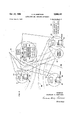
- a still further object is to provide means for operating the' navigational equipment in such manner that position can be determined within Figure l is a block diagram illustrating the basic elements of an hyperbolic system of navigation,
- Figure 2 is a block diagram illustrating a navigational system employing intersecting hyperbolas
- Figure 3 is a block diagram illustrating a three dimensional hyperbolic navigation system
- Figure 4 is a block diagram illustrating the essential components of an elliptical navigating system
- Figure 5 is a block diagram illustrating the essential elements of an elliptical tracking system
- Figure 6 is a block diagram illustrating an elliptical navigation system
- Figure 7 is a block diagram illustrating a combination of elliptical and hyperbolic navigation systems
- Figure 8 is a block diagram illustrating an apparatus arranged so as to combine the elliptical and hyperbolic navigational systems.
- Figure 1 illustrates the basic elements required for determining which hyperbolic line the object being navigated is on. It comprises a fixed relay station I, a second fixed relay station 2, and a reference transmitter 3.
- a mobile transmitter 4, a phase meter 5, receivers I and 8, and constant output amplifiers 9 and ID are mounted on the object being navigated.
- the transmitters 3 and 4 are tuned to different frequencies within the same channel, and the beats between these frequencies are received and detected at relay stations I and 2, respectively.
- Another object is to provide a navigational system in which the navigational data can be obtained at the mobile object, at any other' desired location, or both.
- a still further object is to provide anelliptical navigational system.
- a still further object is to provide, incombination, an hyperbolic system and an elliptical system such that the intersections of the Although the frequency detected at each relay station is equal to the difference between the transmitted frequencies from transmitters 3 and 4, the phase of these detected'beat frequencies isdifierent for different positions of the navigated object; These beat frequencies are relayed back to separate receivers 1 and 8' on the navigated object and the outputs of these receivers are equalized byconstant output amplifiers 9 and I0, respectively, the outputs of the amplifiers 9 being fed to the/phase meter 5.
- Figure 2 shows a means for getting navigational data with respect to two families of hyperbolas and, therefore, getting a fix on the position of the mobile transmitter which comprises the mobile transmitter I4, a reference transmitter I6 and relay stations I8, 20 and 22 located at predetermined positions.
- the relay stations are provided with receivers 24, 26 and 28 that are capable of receiving emissions from both transmitters I4 .and I6, detecting the beat frequency between them and modulating the transmitters 30, 32 and 34, respectively, with the detected beat frequencies.
- Each of these relaying transmitters is operated on a unique carrier frequency and receivers 36, 38 and 40 are tuned to receive the emissions from transmitters 32, 30 and 34, respectively.
- the relayed beat frequencies are detected by these receivers, the output of receiver 36 is fed to each of the phase meters 42 and 44, the output of receiver 38 is fed to phase meter 42, and the output of receiver 40 is fed to phase meter 44.
- Constant output amplifiers 33, 35, and 31 are supplied at the relay stations to hold the modulation level on the relay transmitter.
- phase meter 42 shows the change in the difference between the distances between the mobile transmitter I4 and each of the two relay stations I8 and '20, respectively. or, in other words, such integration indicates the number of hyperbolic lines 48 that have been crossed since leaving the known position.
- the integration of the changes in phase indicated by phase meter 44 from the same known point likewise indicates the number of hyperbolic lines 50 that have been crossed. It is obvious that a reversal in direction with respect to either pair of relay stations causes the corresponding phase meter to reverse its direction also.
- the phase meters employed may be of any conventional type of integrating phase meter, such as, for example, that disclosed in Affel U. S. Patent'No. 1,562,485.
- the receivers 35, 38 and 40 may be located on the navigated object.
- the relay stations might be located on three ships or three aircraft, each of which are equipped with navigational equipment herein described so as to determine their relative positions and the position of an unknown transmitter I4 might bedetermined even during a brief transmission.
- Figures 4 and 5 illustrate an elliptical system for navigation and tracking.
- the basic difference between Figures 4 and 5 is whether the phase meter is located at the mobile station or at a fixed point
- Figure 4 shows a fixed transmitter 64, a mobile transmitter 66, a fixed relay station 68 having a receiving means I0 capable of detecting the beat frequencies between the mobile transmitter 66 and the stationary transmitter 64, and a transmitter 12 that is operated on a unique frequency and modulated by the output of receiver I0.
- Mobile receiver II located in the vicinity of transmitter 66 is tuned to detect the beat frequency between transmitter 66 and transmitter 64
- receiver I4 is tuned toreceive the emissions from transmitter I2 and detect the beat frequency between transmitters 64 and 66 as relayed therefrom.
- the outputs of the receivers II and I4 are fed into constant output amplifiers I6 and 18, respectively, and the outputs of the latter amplifiers are, in turn, fed to phase meter 84.
- the indication of the phase meter does not change, thus indicating that the mobile station is moving along an ellipse which has the fixed transmitter 64 as one focal point and the fixed relay station III as the other.
- Figure 5 shows a variation of the elliptical system that is suited for tracking purposes. It comprises a fixed transmitter 90, a mobile transmitter 92 mounted on an object being tracked, a mobile receiver 94 capable of receiving and detecting the output of both the fixed and-the mobile transmitters, means for modulating transmitter 96 with the detected output of receiver 94,
- receiver 88 capable of receiving emissions from transmitter 88, an equalizing amplifier I 02 for receiver I00, an equalizing amplifier I08 for receiver 88, and a phase indicator I 00.
- the phase of the beat frequency between transmitters 80 and 82 which, for convenience, may be operated in the same channel, are compared as they are received at receivers 84 and 88, respectively.
- the object being tracked comprising transmitters 82 and 88 and receiver 84 follows an elliptical path with transmitter 80 and receiver 98 being the focal points.
- phase meter could be located at both the mobile and fixed positions and thereby give navigational information as well as tracking information.
- transmitter 84 is now a focal point for two families of ellipses, one having another focal point in the fixed station 88 and the other having a focal point at the fixed station IIO.
- An additional receiver H2 is required to detect the beat frequency between transmitter 88 and 84 as it is received at receiver I 08 and relayed by transmitter I08 and, in addition, switching means Ill is required to compare the phase of the beat frequency as detected at receiver 10 with the phase of the beat frequency as detected at. receiver I08.
- the carrier frequencies of transmitters I08 and I2 are different from each other and are not in the same channel as transmitters 84 and 88. It is also to be understood that the relaying of the detected beat frequencies from receivers 10 and I08 could be accomplished by cables, F. M. transmitters or any other known means. The necessity for integrating the changes in phase with respect to both families of ellipses is still present and the method of overcoming this difficulty will be discussed below.
- Figure 7 illustrates a two dimensional tracking system that is similar to Figure except that it has an additional relay station II8 comprising a receiver I I8 capable of detecting the beat frequency between transmitters and 82 and means for modulating the output of transmitter I20 with this detected beat frequency.
- the tracking station must be equipped with a means I22-for receiving the output of transmitter I20, and means I24 for switching the input to the constant output amplifier I02 from receiver I00 to the receiver -I22. It would be possible, of course, to have arr-additional phase indicator but successive determinations of ellipse with respect to the families of ellipses is satisfactory for most purposes.
- the emissions from transmitters 84 and 88 are received by receiver I28 and means is provided for modulating transmitter I30 with the beat frequency thus detected. It is necessary that an additional receiver I32 be provided at the mobile station for receiving the output of the transmitter I30 and that switching means I30 be provided to hook the output of the receiver I32 with the input to the constant output amplifier 18 in order that the phase indicator may give an indication corresponding to the hyperbolic system.
- an additional receiver I32 be provided at the mobile station for receiving the output of the transmitter I30 and that switching means I30 be provided to hook the output of the receiver I32 with the input to the constant output amplifier 18 in order that the phase indicator may give an indication corresponding to the hyperbolic system.
- position can be determined without reference to any past position and both of them depend upon the fact that if the carrier frequency of either or both of the heterodyning transmitters, 3 and 4 for example, is changed, that a change in phase of the beat frequencies is produced. It further depends upon the fact that the change in phase is of 7 successively different magnitudes as the reference points, stations I and 2, of Figure 1, for example, are approached.
- the phase indicator In passing from one of the solid hyperbolic lines in Figure 1 to another, the phase indicator goes through one revolution or 360 degrees and the area between each hyperbolic line is called a lane.
- a new family of hyperbolic lines indicated bythe dotted lines, is set up and the distance between the dotted line and the corresponding solid line is indicative of the amount of phase change that takes place if one were located initially on the solid lines. If the object is located at points in between the solid lines, the phase change is an intermediate amount and it is not necessary that the exact value of this amount be determined for as long as the readings are between the phase changes attwo successive, solid lines, the lane is determined.
- the phase indications may have direct significance and do not have to be calculated each time.
- Another method of obtaining lane identification is to interchange the frequency of transmitter 3 with that of transmitter 6. Whereas the beat frequency remains the same, a phase change in the beat frequencies is produced because the distances of transmission for the two frequencies have been changed.
- An alternative method of achieving the same results and maintaining the same beat frequency is by changing one of the transmitters to a frequency on the other side of the other transmitter, the difference in the frequencies being kept the same. This has an effect on the change in phase similar to that produced when both of the transmitters are changed in frequency and the difference between them is maintained constant.
- the change in the phase difference as the transmitters are operated first at one frequency and then at another is gradual and has a direct relation to the distances-involved.
- the amount of frequency change that can be produced in the standard allotted channels is slight, it is posssible to use this method only for purposes of lane identification.
- a navigation system comprising a mobile transmitter and a fixed transmitter, said transmitters being tuned to operate at different frequencies, a plurality of spaced means for receiving the transmissions of said transmitters and detecting the beat frequency therebetween, and means for relaying the beat frequencies so detected to a common point.
- a navigation system according to claim 1, wherein said common point is at said mobile transmitter.
- a navigation system comprising a mobile transmitter and a fixed transmitter, said transmitters being tuned to operate at different frequencies, a plurality of spaced means for receiving the transmissions of said transmitters and detecting the beat frequency therebetween, means for relaying the beat frequencies so detected to a common point, and means at said common point It is only necessary to determine the for indicating the difference in phase between said detected beat frequency signals.
- a navigation system according to claim 5, wherein said common point is at said mobile transmitter.
- a navigation system according 'to claim 5, wherein said plurality of spaced receiving means are fixed.
- a navigation system comprising a mobile transmitter and a fixed transmitter, said transmitters being tuned to operate at different fre quencies, a plurality of spaced means for receiving the transmissions of said transmitters and detecting the beat frequency therebetween, means for relaying the beat frequencies so detected to a plurality of common points, and means at each of said common points for indicating the difference in phase between said detected beat frequency signals.
- a navigation system according to claim 9, wherein one of said common points is fixed and another of said common points is at said mobile transmitter.
- a two-dimensional navigation system com prising a mobile transmitter and a fixed transmitter, said transmitters being tuned to operate at different frequencies, three spaced means for receiving the transmissions of said transmitters and detecting the beat frequency therebetween, means associated with each of said spaced receiving means for relaying the beat frequencies so detected to a common point, and means at said common point for indicating the difference in phase between two pairs of said detected beat frequency signals.
- a three-dimensional navigation system comprising a mobile transmitter and a fixed transmitter, said transmitters being tuned to operate at different frequencies, four spaced means for receiving the transmissions of said transmitters and detecting the beat frequency therebetween, means associated with each of said spaced receiving means for relaying the beat frequencies so detected to a common point, and means at said common point for indicating the difference in phase between three pairs of said beat frequency signals.
- a navigation system comprising a mobile transmitter and a fixed transmitter, said transmitters being tuned to operate at slightly different frequencies, a plurality of spaced means for receiving the transmissions of said transmitters and detecting the beat frequency therebetween, means for transmitting the beat frequencies so detected at unique frequencies, means at a common point for receiving the detected beat frequency signals transmitted at said unique frequencies, and means at said common point for indicating the difference in phase between said detected beat frequency signals.
- a navigation system comprising a mobile transmitter and a fixed transmitter, said transmitters being tuned to operate at different frequencies, a plurality of spaced means for receiving the transmissions of said transmitters and detecting the beat frequency therebetween, means for relaying the beat frequencies so detected to a common point, and means at said common point for indicating and integrating the difference in phase between said detected beat frequency signals.
- a navigation system comprising a mobile transmitter and a fixed transmitter, said transmitters being tuned to operate at different frequencies, a plurality of spaced means for receiving the transmissions of said transmitters and detecting the beat frequency therebetween, means for transmitting the beat frequencies so detected at unique frequencies, means at a common point for receiving the detected beat frequency signals transmitted at said unique frequencies, means for equalizing the output of said receivers at said common point, and means for separately indicating the diiference in phase between the output of one of said receivers with the output of each of two others of said receivers.
- An elliptical navigation system comprising a mobile transmitter and a fixed transmitter, said transmitters being tuned to operate at different frequencies, a plurality of spaced means for receiving the transmissions of said transmitters and detecting the beat frequency therebetween, one of said spaced receiving means being positioned at said moble transmitter and the other being fixed, means for relaying the beat frequencies so detected to a common point, and means at said common point for indicating the difference in phase between said detected beat frequency signals.
- a two-dimensional elliptical navigation system comprising a mobile transmitter and 'a fixed transmitter, said transmitters being tuned to operate at different frequencies, three spaced means for receiving the transmissions of said transmitters and detecting the beat frequency therebetween, one of said spaced receiving means being positioned at said mobile transmitter and the others beingfixed, means associated with each of said spaced receiving means for relaying the beat frequencies so detected to a common point, and means at said common point for indicating the difference in phase between two pairs of said detected beat frequency signals.
- a two-dimensional elliptical navigation system according to claim 19, wherein said common point is also at said mobile transmitter.
- a two-dimensional elliptical navigation system according to claim 19, wherein said common point is at one of said fixed receiving means.
- a two-dimensional combined elliptical and hyperbolic navigation system comprising a mobile transmitter and a fixed transmitter, said transmitters being tuned to operate at different frequencies, three spaced means for receiving the transmissions of said transmitters and detecting the beat frequency therebetween, one of said spaced receiving means being positioned at said mobile transmitter, another of said spaced receiving means being fixed in the vicinity of said fixed transmitter and the third of said spaced receiving means being fixed, means associated with each of said spaced receiving means for relaying the beat frequencies so detected to a common point andmeans at said common point for indicating the difference in phase between two pairs of said detected beat frequency signals.
- a navigation system including means for changing the operating frequency of one of said transmitters and means for indicating the resultant change in phase difference eifected thereby at said common point.
- a navigational method of lane identification comprising the steps of transmitting from two spaced transmitters at different frequencies, detecting the beat frequency between said transmissions at two spaced points, relaying the beat frequencies so detected to a common point, measuring the difference in phase between said beat frequencies at said common point, changing the operating frequency of one of said transmitters, and measuring the resultant change in phase difference efl'ected thereby at said common point.
- a navigational method of lane identification comprising the steps of transmitting from two spaced transmitters at different frequencies, detecting the beat frequency between said transmissions at two spaced points, relaying the beat frequencies so detected to a common point, measuring the difference in phase between said heat frequencies at said common point, changing the operating frequency of one of said transmitters,
- a navigational method of lane identification comprising the steps of transmitting from two spaced transmitters, the operating. fre-' quencies .of said transmitters differing by an audio note, detecting the beat frequency between said transmissions at two spaced points, relaying the beat frequencies so detected to a common point, measuring the difference in phase between said heat frequencies at said common point, changing the operating frequency of one of said transmitters to a frequency also differing from that of the other of said transmitters by an audio note, and measuring the resultant change in phialste difference effected thereby at said common D 28.
- a navigational method of lane identification comprising the steps of transmitting from two spaced transmitters, the operating frequencies of said transmitters differing by an audio note, detecting the beat frequency between said transmissions at two spaced points, relaying the beat frequencies so detected to a common point, measuring the difference in phase between said beat frequencies at said common point, interchanging the operating frequency of said transmitters, and measuring the magnitude and direction of the resultant change in phase difl'erence effected at said common point.
Landscapes
- Engineering & Computer Science (AREA)
- Computer Networks & Wireless Communication (AREA)
- Physics & Mathematics (AREA)
- General Physics & Mathematics (AREA)
- Radar, Positioning & Navigation (AREA)
- Remote Sensing (AREA)
- Position Fixing By Use Of Radio Waves (AREA)
Description
1950 c. E. HASTINGS 2,528,
NAVIGATION AND TRACKING APPARATUS Filed June 8. 194a s Sheets-Sheet 1 PHASE METER FIG. I.
TRANS REC FIG. 4.
4 66 TRANS REC L AMPL AMPL W 78 PHASE- METER Rac Inventor CHARLES E. HASTINGS Attorneys Oct. 31, 1950 c. E. HASTINGS NAVIGATION AND TRACKING APPARATUS Filed June 8, 1948 ONE 025:. mum w 8 NM mm m G :52. m m 1 e T v M m H is? B S E uuk L I M om w I mm m 1 p I I}. l I I on mm v b s2 25:. A I umm N 0E m.
A'Horneys Oct. 31, 1950 c. E. HASTINGS NAVIGATION AND TRACKING APPARATUS 5 Sheets-Sheet 3 Filed June 8, 1948 u I l I I l \l 323 $5. 322.
QUE
Inventor CHARLES E. HASTINGS Attorheys 0 c. E. HASTINGS 2,523,141
NAVIGATION AND TRACKING APPARATUS Filed June 8. 1948 5 Sheets-Sheet 4 v I FIG. 5.
{I 9 TRANS TRANs I 94 Rec l I o E o I 92- TRANS vmac I REC 'mm. AMPL 103 A PHASE METE I04 FIG. 6. 66
TRANS REC.
REC
AMPL. 4 AMPL PHASE METER Inventor CHARLES E. HASTINGS Attorneys Oct. 31, 1950 c; E. HASTINGS NAVIGATION AND TRACKING APPARATUS Filed June 8, 1948 -uR FIG. us'\. 96/ TRANS 90 l. TRANS I0! REC REC
92/ TRANS REC REC
5 Sheets-Sheet 5 '03 AM FL I AMPLIrIOZ PHA METER TRANS 4 AMPL AMPL PHASE METER FIG. 8.
Inventor CHARLES E. HASTINGS AHorneys Patented Oct. 31, 1950 UNITED STATES PATENT caries NAVIGATION AND TRACKING APPARATUS Charles E. Hastings, Hampton, Va., assignor to Hastings Instrument Company, Inc., Hampton, Va., a corporation of Virginia Application June 8,1948, Serial No. 31,682
28 Claims. 1
This invention relates to navigational equipment that is operated on theprinciple of phase comparison of the carrier frequency waves.
Although many different types of navigational equipment have been devised, none of them are able to indicate position within a matter of inches. Such accuracy becomes necessary in many operations such as exploring for oil, guiding missiles, and controlling gun fire. Furthermore, the elements of this system are comprised of standard radio transmitters and receivers which can be used for other purposes.
In phase operated navigational systems in which the distances to be determined are a fractional part of the wave lengths being used, it is not necessary to provide for what is known as lane identification. However, these systems are not as accurate as system in which the wave length of the frequencies being used is less than Another object is to provide accurate navi-v gational equipment using standard transmitters and receivers.
A still further object is to provide accurate navigational equipment such that variations in the transmitted frequencies produce errors of a second order of magnitude.
A still further object is to provide means for operating the' navigational equipment in such manner that position can be determined within Figure l is a block diagram illustrating the basic elements of an hyperbolic system of navigation,
Figure 2 is a block diagram illustrating a navigational system employing intersecting hyperbolas,
Figure 3 is a block diagram illustrating a three dimensional hyperbolic navigation system,
Figure 4 is a block diagram illustrating the essential components of an elliptical navigating system,
Figure 5 is a block diagram illustrating the essential elements of an elliptical tracking system,
Figure 6 is a block diagram illustrating an elliptical navigation system,
Figure 7 is a block diagram illustrating a combination of elliptical and hyperbolic navigation systems, and
Figure 8 is a block diagram illustrating an apparatus arranged so as to combine the elliptical and hyperbolic navigational systems.
Figure 1 illustrates the basic elements required for determining which hyperbolic line the object being navigated is on. It comprises a fixed relay station I, a second fixed relay station 2, and a reference transmitter 3. A mobile transmitter 4, a phase meter 5, receivers I and 8, and constant output amplifiers 9 and ID are mounted on the object being navigated. In operation, the transmitters 3 and 4 are tuned to different frequencies within the same channel, and the beats between these frequencies are received and detected at relay stations I and 2, respectively.
the nearest wave length of the carrier frequency being used.
Another object is to provide a navigational system in which the navigational data can be obtained at the mobile object, at any other' desired location, or both.
A still further object is to provide anelliptical navigational system.
A still further object is to provide, incombination, an hyperbolic system and an elliptical system such that the intersections of the Although the frequency detected at each relay station is equal to the difference between the transmitted frequencies from transmitters 3 and 4, the phase of these detected'beat frequencies isdifierent for different positions of the navigated object; These beat frequencies are relayed back to separate receivers 1 and 8' on the navigated object and the outputs of these receivers are equalized byconstant output amplifiers 9 and I0, respectively, the outputs of the amplifiers 9 being fed to the/phase meter 5.
As long as the difference in the distance betweena -navigatedobject and the two relay stations land 2 is thefsame, the indications of the phase indicator remain unchanged, thus in- 2 being the focal points.
Thus, it is seen that for every change in the difference of the distances between the navigated 'object and the two relay stations equal to one wave length of the carrier frequencies that the phase indicator rotates 360 and that if the wave length is less than the distances involved, it is necessary to start from a known positionand integrate the changes in phase as the object isnavigated. The disadvantage of this system is readily apparent for if for some reason the object moves into a different lane while the navigational equipment is out of operation, there is no indication of the new lane of position.
Figure 2 shows a means for getting navigational data with respect to two families of hyperbolas and, therefore, getting a fix on the position of the mobile transmitter which comprises the mobile transmitter I4, a reference transmitter I6 and relay stations I8, 20 and 22 located at predetermined positions. The relay stations are provided with receivers 24, 26 and 28 that are capable of receiving emissions from both transmitters I4 .and I6, detecting the beat frequency between them and modulating the transmitters 30, 32 and 34, respectively, with the detected beat frequencies. Each of these relaying transmitters is operated on a unique carrier frequency and receivers 36, 38 and 40 are tuned to receive the emissions from transmitters 32, 30 and 34, respectively. The relayed beat frequencies are detected by these receivers, the output of receiver 36 is fed to each of the phase meters 42 and 44, the output of receiver 38 is fed to phase meter 42, and the output of receiver 40 is fed to phase meter 44.
Starting from a known position with respect to the relay stations I6, 20 and 22, integration of the changes in phase indicated by phase meter 42 shows the change in the difference between the distances between the mobile transmitter I4 and each of the two relay stations I8 and '20, respectively. or, in other words, such integration indicates the number of hyperbolic lines 48 that have been crossed since leaving the known position. The integration of the changes in phase indicated by phase meter 44 from the same known point, likewise indicates the number of hyperbolic lines 50 that have been crossed. It is obvious that a reversal in direction with respect to either pair of relay stations causes the corresponding phase meter to reverse its direction also. The phase meters employed may be of any conventional type of integrating phase meter, such as, for example, that disclosed in Affel U. S. Patent'No. 1,562,485.
In the navigational equipment described above, the receivers 35, 38 and 40 may be located on the navigated object. The indications of these phase and the other located at some fixed position 54 for tracking data.
It is understood that the determination of the position of transmitter I4 is relative with respect to the relay station's I8, 20 and 22 and that the position of the reference transmitter I6, as long as it is fixed with respect to the relay stations, need not be known.
It is possible to get a fix on an unknown mobile transmitter I 4 by heterodyning its emissions with the emissions from a reference transmitter I6. For example, the relay stations might be located on three ships or three aircraft, each of which are equipped with navigational equipment herein described so as to determine their relative positions and the position of an unknown transmitter I4 might bedetermined even during a brief transmission.
It is entirely possible, as shown in Figure 3, to obtain three dimensional data by the addition of a fourth relay station 45 operated on a fourth unique frequency and located so as not to be in the plane determined by the relay stations I8, 20 and 22. In such a system, it would be necessary to add an additional receiver 60 that is tuned to this fourth unique frequency and a phase meter 62. The phase of the beat frequency as relayed to receiver 60 from relay station 45 could then be compared with the phase of the beat frequency in the outputs of any of the receivers 36, 38 and 40 to determine position in space. By such a method, accurate information can be obtained as to the position of a guided missile with respect to the four relay stations and the missile need only carry a transmitter.
Figures 4 and 5 illustrate an elliptical system for navigation and tracking. The basic difference between Figures 4 and 5 is whether the phase meter is located at the mobile station or at a fixed point, Figure 4 shows a fixed transmitter 64, a mobile transmitter 66, a fixed relay station 68 having a receiving means I0 capable of detecting the beat frequencies between the mobile transmitter 66 and the stationary transmitter 64, and a transmitter 12 that is operated on a unique frequency and modulated by the output of receiver I0. Mobile receiver II located in the vicinity of transmitter 66 is tuned to detect the beat frequency between transmitter 66 and transmitter 64, and receiver I4 is tuned toreceive the emissions from transmitter I2 and detect the beat frequency between transmitters 64 and 66 as relayed therefrom. The outputs of the receivers II and I4 are fed into constant output amplifiers I6 and 18, respectively, and the outputs of the latter amplifiers are, in turn, fed to phase meter 84.
In operation, as long as the sum of the distances between the mobile transmitter and the fixed receiver vIII and the fixed transmitter 64 remain constant, the indication of the phase meter does not change, thus indicating that the mobile station is moving along an ellipse which has the fixed transmitter 64 as one focal point and the fixed relay station III as the other.
Figure 5 shows a variation of the elliptical system that is suited for tracking purposes. It comprises a fixed transmitter 90, a mobile transmitter 92 mounted on an object being tracked, a mobile receiver 94 capable of receiving and detecting the output of both the fixed and-the mobile transmitters, means for modulating transmitter 96 with the detected output of receiver 94,
fixed receiver IDII capable of receiving and detecting emissions from transmitters and 92, a
receiver 88 capable of receiving emissions from transmitter 88, an equalizing amplifier I 02 for receiver I00, an equalizing amplifier I08 for receiver 88, and a phase indicator I 00. In operation, the phase of the beat frequency between transmitters 80 and 82 which, for convenience, may be operated in the same channel, are compared as they are received at receivers 84 and 88, respectively. Thus, as the 'sum of the distances between the fixed transmitter 80, the mobile transmitter 92, and the receiver 88 remains constant, the object being tracked comprising transmitters 82 and 88 and receiver 84 follows an elliptical path with transmitter 80 and receiver 98 being the focal points.
y In both of the elliptical. systems discussed above, it is apparent that if the distance between the mobile units and the fixed units is less than a. full wave length of the carrier frequencies transmitted from the mobile and fixed transmitters that there is no need of a lane identification system. However, as pointed out in connection with the hyperbolic systems, extreme accuracy requires that there be a small amount of distance per degree of the phase indicator readin and that, therefore, the wave length of the carrier frequencies used in the mobile and fixed transmitters be small in comparison with the distances being determined. It is possible to determine which ellipse of the family of ellipses the mobile object is on by starting from a known position and integrating the changes in the phase indicator readings. However, as pointed out, this necessitates that the system be kept in operation continuously as one proceeds from a known point if changes in lane are to be determined.
It is readily apparent that the phase meter could be located at both the mobile and fixed positions and thereby give navigational information as well as tracking information.
In order to get a fix on any position, it is necessary to determine not only which of the family of ellipses the object is on but the position on this ellipse as well. This can be done by setting up, as shown in Figure 6, an additional relay station IIO comprising receiver I08 and transmitter I08. The corresponding component parts of Figure 4 and Figure 6 are indicated by the same numerals. Thus, transmitter 84 is now a focal point for two families of ellipses, one having another focal point in the fixed station 88 and the other having a focal point at the fixed station IIO. An additional receiver H2 is required to detect the beat frequency between transmitter 88 and 84 as it is received at receiver I 08 and relayed by transmitter I08 and, in addition, switching means Ill is required to compare the phase of the beat frequency as detected at receiver 10 with the phase of the beat frequency as detected at. receiver I08. The carrier frequencies of transmitters I08 and I2 are different from each other and are not in the same channel as transmitters 84 and 88. It is also to be understood that the relaying of the detected beat frequencies from receivers 10 and I08 could be accomplished by cables, F. M. transmitters or any other known means. The necessity for integrating the changes in phase with respect to both families of ellipses is still present and the method of overcoming this difficulty will be discussed below.
Figure 7 illustrates a two dimensional tracking system that is similar to Figure except that it has an additional relay station II8 comprising a receiver I I8 capable of detecting the beat frequency between transmitters and 82 and means for modulating the output of transmitter I20 with this detected beat frequency. The tracking station must be equipped with a means I22-for receiving the output of transmitter I20, and means I24 for switching the input to the constant output amplifier I02 from receiver I00 to the receiver -I22. It would be possible, of course, to have arr-additional phase indicator but successive determinations of ellipse with respect to the families of ellipses is satisfactory for most purposes. Thus, if the object being tracked starts from known position and the changes in phase are integrated with respect to the family of ellipses formed with focal points at transmitter 80 and receiver I00 as well as the focal points 80 and relay station II8, the intersection of these two ellipses determines the position.
As shown in Figure 8, it is possible to obtain navigational information by a combination of elliptical and hyperbolic methods discussed above. Extremely accurate results can be obtained by such a system for the reason that the angles of intersection between a family of hyperbolas and a family of ellipses are nearly at right angles. The numerals, wherein possible, correspond to those of Figure 4. If an additional relay station I28 similar to that indicated by numerals 88 through 12 is established in the vicinity of transmitter 84, these two relay stations form the focal points of a hyperbolic system, which points correspond with the focal points of an elliptical system. However, it is not necessary for the operation of a system that the focal points coincide. In operation, the emissions from transmitters 84 and 88 are received by receiver I28 and means is provided for modulating transmitter I30 with the beat frequency thus detected. It is necessary that an additional receiver I32 be provided at the mobile station for receiving the output of the transmitter I30 and that switching means I30 be provided to hook the output of the receiver I32 with the input to the constant output amplifier 18 in order that the phase indicator may give an indication corresponding to the hyperbolic system. Of course, it would be entirely feasible to provide equipment at the mobile station so as to get a continuous reading of both the elliptical and hyperbolic information. Also, as pointed out above, if extreme accuracy is to be obtained by the use of wave lengths that are small in comparison with the distances involved, it will be necessary to start navigation from a known lane and separately integrate the changes in phase with respect to both the elliptical and hyperbolic systems.
In the preferred method of operation of all the of the mobile and fixed transmitters lie within the same channel and line results have been obtained with a 400 cycle separation of these frequencies.
As has been pointed out with respect to all the above navigational and tracking systems, it is necessary to provide means for determining the position of an object without starting at a known point. There are two methods by which position can be determined without reference to any past position and both of them depend upon the fact that if the carrier frequency of either or both of the heterodyning transmitters, 3 and 4 for example, is changed, that a change in phase of the beat frequencies is produced. It further depends upon the fact that the change in phase is of 7 successively different magnitudes as the reference points, stations I and 2, of Figure 1, for example, are approached. Therefore, in Figure 1, if the frequencies of transmitters 3 and 4 are separated by some audible amount such as 400 cycles and both of them are operating in the high frequency part of the channel, it is possible to produce a change in phase meter reading by changing both of their frequencies by the same amount and transferring them to the bottom or low frequency end of the channel. As the mobile transmitter progresses from relay station l to relay station 2, the change in phase thus produced becomes smaller until it is zero at the midpoint and then increases in magnitude from the midpoint to receiving station 2. The change in phase between relay station I and the midpoint and relay station 2 and the midpoint are in opposite directions and, therefore, it is possible to determine which side of the midpoint the object is on. It is readily seen that these relationships hold true whether the object is being navigated or whether it is being tracked.
In passing from one of the solid hyperbolic lines in Figure 1 to another, the phase indicator goes through one revolution or 360 degrees and the area between each hyperbolic line is called a lane. when the frequency of the transmitters 3 and 4 are changed, a new family of hyperbolic lines, indicated bythe dotted lines, is set up and the distance between the dotted line and the corresponding solid line is indicative of the amount of phase change that takes place if one were located initially on the solid lines. If the object is located at points in between the solid lines, the phase change is an intermediate amount and it is not necessary that the exact value of this amount be determined for as long as the readings are between the phase changes attwo successive, solid lines, the lane is determined. Of course, much as inthe system of Loran, charts have to be provided so that the phase indications may have direct significance and do not have to be calculated each time.
Another method of obtaining lane identification is to interchange the frequency of transmitter 3 with that of transmitter 6. Whereas the beat frequency remains the same, a phase change in the beat frequencies is produced because the distances of transmission for the two frequencies have been changed.
An alternative method of achieving the same results and maintaining the same beat frequency is by changing one of the transmitters to a frequency on the other side of the other transmitter, the difference in the frequencies being kept the same. This has an effect on the change in phase similar to that produced when both of the transmitters are changed in frequency and the difference between them is maintained constant.
These methods of lane identification have been discussed with respect to Figure 1 which is a single hyperbolic system. They may be applied to a double hyperbolic system such as is indicated in Figure 2 with equal success as the changes in phase indicated by phase meters 62 and as, respectively, determine the lane with respect to the stations i8 and 20 and 2D and 22. If the mobile transmitter is being tracked, it is obvious that the easiest way to obtain information concerning lane identification is to change the frequency of transmitter 32 onto the other side of the frequency of the mobile transmitter. This method can be of use in determining the position of'an unknown transmitter with respect to three known 8 v I locations by heterodyning it first with a frequency below its carrier frequency, and then heterodyning it with a frequency above its carrier frequency.
It is thought that application of the above methods to a three dimensional system is unnecessary as the methods used are identical.
Similar results are produced in the elliptical systems discussed in connection with Figures 4 through 7 by altering the frequencies of the heterodyning transmitters as described above. In Figure 4, for example, as the transmitter frequencies are changed in accordance :with any of the above methods, the phase meter indications change by amount shown by the .dotted system of ellipses, and it is seen that this phase change gets progressively greater as the object gets further away from the focal points at the fixed stations. change in reading as being between the change that would be produced at two successive solid lines as the normal operation determines the exact position within the lane.
If the changes in the phase indications could be made great enough, it would be" possible to determine position with accuracy because. as
pointed out. above, the change in the phase difference as the transmitters are operated first at one frequency and then at another is gradual and has a direct relation to the distances-involved. However, as the amount of frequency change that can be produced in the standard allotted channels is slight, it is posssible to use this method only for purposes of lane identification.
It is not felt that it is necessary to apply the above systems to the elliptical systems indicated by Figures 5, 6 and 7 or to Figure 8 which illustrates the combination of hyperbolic and eliptical systems and that one skilled in the art could. on
the basis of the above discussion. determine the lane of position in these systems by use of the methods described.
It is believed that the above navigation and tracking systems are unique and that they are a marked advance over any prior art in that they teach a method of using standard transmitters and receiversso as to determine position with extreme accuracy regardless of the distance involved.
I claim:
A navigation system comprising a mobile transmitter and a fixed transmitter, said transmitters being tuned to operate at different frequencies, a plurality of spaced means for receiving the transmissions of said transmitters and detecting the beat frequency therebetween, and means for relaying the beat frequencies so detected to a common point.
2. A navigation system according to claim 1, wherein said common point-is a fixed point.
3. A navigation system according to claim 1. wherein said common point is at said fixed transmitter.
4. A navigation system according to claim 1, wherein said common point is at said mobile transmitter.
5. A navigation system comprising a mobile transmitter and a fixed transmitter, said transmitters being tuned to operate at different frequencies, a plurality of spaced means for receiving the transmissions of said transmitters and detecting the beat frequency therebetween, means for relaying the beat frequencies so detected to a common point, and means at said common point It is only necessary to determine the for indicating the difference in phase between said detected beat frequency signals.
6..A navigation system according to claim 5, wherein said common point is a fixed point.
7. A navigation system according to claim 5, wherein said common point is at said mobile transmitter.
8. A navigation system according 'to claim 5, wherein said plurality of spaced receiving means are fixed.
9. A navigation system comprising a mobile transmitter and a fixed transmitter, said transmitters being tuned to operate at different fre quencies, a plurality of spaced means for receiving the transmissions of said transmitters and detecting the beat frequency therebetween, means for relaying the beat frequencies so detected to a plurality of common points, and means at each of said common points for indicating the difference in phase between said detected beat frequency signals.
10. A navigation system according to claim 9, wherein one of said common points is fixed and another of said common points is at said mobile transmitter.
V 11. A two-dimensional navigation system com prising a mobile transmitter and a fixed transmitter, said transmitters being tuned to operate at different frequencies, three spaced means for receiving the transmissions of said transmitters and detecting the beat frequency therebetween, means associated with each of said spaced receiving means for relaying the beat frequencies so detected to a common point, and means at said common point for indicating the difference in phase between two pairs of said detected beat frequency signals.
12. A three-dimensional navigation system comprising a mobile transmitter and a fixed transmitter, said transmitters being tuned to operate at different frequencies, four spaced means for receiving the transmissions of said transmitters and detecting the beat frequency therebetween, means associated with each of said spaced receiving means for relaying the beat frequencies so detected to a common point, and means at said common point for indicating the difference in phase between three pairs of said beat frequency signals.
13. A navigation system comprising a mobile transmitter and a fixed transmitter, said transmitters being tuned to operate at slightly different frequencies, a plurality of spaced means for receiving the transmissions of said transmitters and detecting the beat frequency therebetween, means for transmitting the beat frequencies so detected at unique frequencies, means at a common point for receiving the detected beat frequency signals transmitted at said unique frequencies, and means at said common point for indicating the difference in phase between said detected beat frequency signals.
14. A navigation system comprising a mobile transmitter and a fixed transmitter, said transmitters being tuned to operate at different frequencies, a plurality of spaced means for receiving the transmissions of said transmitters and detecting the beat frequency therebetween, means for relaying the beat frequencies so detected to a common point, and means at said common point for indicating and integrating the difference in phase between said detected beat frequency signals.
15. A navigation system comprising a mobile transmitter and a fixed transmitter, said transmitters being tuned to operate at different frequencies, a plurality of spaced means for receiving the transmissions of said transmitters and detecting the beat frequency therebetween, means for transmitting the beat frequencies so detected at unique frequencies, means at a common point for receiving the detected beat frequency signals transmitted at said unique frequencies, means for equalizing the output of said receivers at said common point, and means for separately indicating the diiference in phase between the output of one of said receivers with the output of each of two others of said receivers.
16. An elliptical navigation system comprising a mobile transmitter and a fixed transmitter, said transmitters being tuned to operate at different frequencies, a plurality of spaced means for receiving the transmissions of said transmitters and detecting the beat frequency therebetween, one of said spaced receiving means being positioned at said moble transmitter and the other being fixed, means for relaying the beat frequencies so detected to a common point, and means at said common point for indicating the difference in phase between said detected beat frequency signals.
1'7. An elliptical navigation system according to claim 16, wherein said common point is also at said mobile transmitter.
18. An elliptical navigation system according to claim 16, wherein said common point is at the fixed receiving means.
19. A two-dimensional elliptical navigation system comprising a mobile transmitter and 'a fixed transmitter, said transmitters being tuned to operate at different frequencies, three spaced means for receiving the transmissions of said transmitters and detecting the beat frequency therebetween, one of said spaced receiving means being positioned at said mobile transmitter and the others beingfixed, means associated with each of said spaced receiving means for relaying the beat frequencies so detected to a common point, and means at said common point for indicating the difference in phase between two pairs of said detected beat frequency signals.
20. A two-dimensional elliptical navigation system according to claim 19, wherein said common point is also at said mobile transmitter.
21. A two-dimensional elliptical navigation system according to claim 19, wherein said common point is at one of said fixed receiving means.
22. A two-dimensional combined elliptical and hyperbolic navigation system comprising a mobile transmitter and a fixed transmitter, said transmitters being tuned to operate at different frequencies, three spaced means for receiving the transmissions of said transmitters and detecting the beat frequency therebetween, one of said spaced receiving means being positioned at said mobile transmitter, another of said spaced receiving means being fixed in the vicinity of said fixed transmitter and the third of said spaced receiving means being fixed, means associated with each of said spaced receiving means for relaying the beat frequencies so detected to a common point andmeans at said common point for indicating the difference in phase between two pairs of said detected beat frequency signals.
23. A navigation system according to claim 5, including means for changing the operating frequency of one of said transmitters and means for indicating the resultant change in phase difference eifected thereby at said common point.
24. A navigation system according to claim 5,
including means for changing the operating frequency of both of said transmitters and means for indicating the resultant change in phase difference efiected thereby at said common point.
25. A navigational method of lane identification comprising the steps of transmitting from two spaced transmitters at different frequencies, detecting the beat frequency between said transmissions at two spaced points, relaying the beat frequencies so detected to a common point, measuring the difference in phase between said beat frequencies at said common point, changing the operating frequency of one of said transmitters, and measuring the resultant change in phase difference efl'ected thereby at said common point.
26. A navigational method of lane identification comprising the steps of transmitting from two spaced transmitters at different frequencies, detecting the beat frequency between said transmissions at two spaced points, relaying the beat frequencies so detected to a common point, measuring the difference in phase between said heat frequencies at said common point, changing the operating frequency of one of said transmitters,
and measuring the magnitude and direction of the resultant change in phase difference effected at said common point.
27. A navigational method of lane identification comprising the steps of transmitting from two spaced transmitters, the operating. fre-' quencies .of said transmitters differing by an audio note, detecting the beat frequency between said transmissions at two spaced points, relaying the beat frequencies so detected to a common point, measuring the difference in phase between said heat frequencies at said common point, changing the operating frequency of one of said transmitters to a frequency also differing from that of the other of said transmitters by an audio note, and measuring the resultant change in phialste difference effected thereby at said common D 28. A navigational method of lane identification comprising the steps of transmitting from two spaced transmitters, the operating frequencies of said transmitters differing by an audio note, detecting the beat frequency between said transmissions at two spaced points, relaying the beat frequencies so detected to a common point, measuring the difference in phase between said beat frequencies at said common point, interchanging the operating frequency of said transmitters, and measuring the magnitude and direction of the resultant change in phase difl'erence effected at said common point.
CHARLES E. HASTINGS.
REFERENCES CITED The following references are of record in the O'Brien Oct. 4, 1949
Priority Applications (1)
| Application Number | Priority Date | Filing Date | Title |
|---|---|---|---|
| US31682A US2528141A (en) | 1948-06-08 | 1948-06-08 | Navigation and tracking apparatus |
Applications Claiming Priority (1)
| Application Number | Priority Date | Filing Date | Title |
|---|---|---|---|
| US31682A US2528141A (en) | 1948-06-08 | 1948-06-08 | Navigation and tracking apparatus |
Publications (1)
| Publication Number | Publication Date |
|---|---|
| US2528141A true US2528141A (en) | 1950-10-31 |
Family
ID=21860837
Family Applications (1)
| Application Number | Title | Priority Date | Filing Date |
|---|---|---|---|
| US31682A Expired - Lifetime US2528141A (en) | 1948-06-08 | 1948-06-08 | Navigation and tracking apparatus |
Country Status (1)
| Country | Link |
|---|---|
| US (1) | US2528141A (en) |
Cited By (7)
| Publication number | Priority date | Publication date | Assignee | Title |
|---|---|---|---|---|
| US2709807A (en) * | 1952-09-02 | 1955-05-31 | Int Standard Electric Corp | Radio navigation |
| US2724114A (en) * | 1950-10-16 | 1955-11-15 | Shell Dev | Phase-comparison radiolocation system |
| US2839749A (en) * | 1952-07-08 | 1958-06-17 | Carleton Henry | Precision electronic navigation system |
| US2856601A (en) * | 1955-07-06 | 1958-10-14 | Seismograph Service Corp | Radio location system |
| US3101471A (en) * | 1950-02-04 | 1963-08-20 | Int Standard Electric Corp | Radio direction indicator |
| US3206752A (en) * | 1961-06-19 | 1965-09-14 | Decca Ltd | Radio navigational systems |
| US3206751A (en) * | 1959-10-06 | 1965-09-14 | David Q Reed | Electronic location and guidance system |
Citations (6)
| Publication number | Priority date | Publication date | Assignee | Title |
|---|---|---|---|---|
| US1562485A (en) * | 1923-05-05 | 1925-11-24 | American Telephone & Telegraph | Movement and position indicator |
| US2405238A (en) * | 1940-04-13 | 1946-08-06 | Rca Corp | Position determining system |
| US2408773A (en) * | 1942-03-31 | 1946-10-08 | Bell Telephone Labor Inc | Position determining system |
| US2440755A (en) * | 1945-08-27 | 1948-05-04 | Decca Record Co Ltd | Radio-frequency navigation system |
| USRE23050E (en) * | 1944-03-02 | 1948-11-23 | Radio beacon | |
| US2483558A (en) * | 1945-08-27 | 1949-10-04 | Decca Record Co Ltd | Area identification system |
-
1948
- 1948-06-08 US US31682A patent/US2528141A/en not_active Expired - Lifetime
Patent Citations (6)
| Publication number | Priority date | Publication date | Assignee | Title |
|---|---|---|---|---|
| US1562485A (en) * | 1923-05-05 | 1925-11-24 | American Telephone & Telegraph | Movement and position indicator |
| US2405238A (en) * | 1940-04-13 | 1946-08-06 | Rca Corp | Position determining system |
| US2408773A (en) * | 1942-03-31 | 1946-10-08 | Bell Telephone Labor Inc | Position determining system |
| USRE23050E (en) * | 1944-03-02 | 1948-11-23 | Radio beacon | |
| US2440755A (en) * | 1945-08-27 | 1948-05-04 | Decca Record Co Ltd | Radio-frequency navigation system |
| US2483558A (en) * | 1945-08-27 | 1949-10-04 | Decca Record Co Ltd | Area identification system |
Cited By (8)
| Publication number | Priority date | Publication date | Assignee | Title |
|---|---|---|---|---|
| US3101471A (en) * | 1950-02-04 | 1963-08-20 | Int Standard Electric Corp | Radio direction indicator |
| US2724114A (en) * | 1950-10-16 | 1955-11-15 | Shell Dev | Phase-comparison radiolocation system |
| US2839749A (en) * | 1952-07-08 | 1958-06-17 | Carleton Henry | Precision electronic navigation system |
| US2709807A (en) * | 1952-09-02 | 1955-05-31 | Int Standard Electric Corp | Radio navigation |
| DE962902C (en) * | 1952-09-02 | 1957-05-02 | Int Standard Electric Corp | Arrangement for steering an aircraft into an approach zone of an airport that defines the landing course |
| US2856601A (en) * | 1955-07-06 | 1958-10-14 | Seismograph Service Corp | Radio location system |
| US3206751A (en) * | 1959-10-06 | 1965-09-14 | David Q Reed | Electronic location and guidance system |
| US3206752A (en) * | 1961-06-19 | 1965-09-14 | Decca Ltd | Radio navigational systems |
Similar Documents
| Publication | Publication Date | Title |
|---|---|---|
| US2198113A (en) | Navigation method and apparatus | |
| US2408048A (en) | Radio direction method and system | |
| US3430234A (en) | Navigation systems using earth satellites | |
| JPS58129277A (en) | Radio navigation device of hyperbola system | |
| US5572427A (en) | Doppler position bearing angle locator | |
| US2528141A (en) | Navigation and tracking apparatus | |
| US3863256A (en) | Method and apparatus for developing relative direction and distance data | |
| US2513315A (en) | Radio position determining system | |
| US2940076A (en) | Passive position determining system | |
| US2413620A (en) | Direction finding system | |
| US2582971A (en) | Pulse echo distance and direction finding | |
| US3808597A (en) | Iso-phase position determining system | |
| US2440755A (en) | Radio-frequency navigation system | |
| US2611127A (en) | Continuous wave navigation system | |
| US4350984A (en) | Method of position fixing active sources utilizing differential doppler | |
| US1998834A (en) | Radio guiding system | |
| US2742638A (en) | Radio ranging system | |
| US2728909A (en) | Non-ambiguous cycle matching radio navigation system | |
| US3025517A (en) | Simultaneous lobe comparison for radar direction finding | |
| US2432625A (en) | Apparatus for and method of locating submarines | |
| US2513320A (en) | Radio position determining system | |
| US2483558A (en) | Area identification system | |
| US2616079A (en) | Navigation lane identification | |
| US2513314A (en) | Geophysical prospecting system | |
| US2513321A (en) | Radio location system |