US2528137A - Lens grinding machine - Google Patents
Lens grinding machine Download PDFInfo
- Publication number
- US2528137A US2528137A US781288A US78128847A US2528137A US 2528137 A US2528137 A US 2528137A US 781288 A US781288 A US 781288A US 78128847 A US78128847 A US 78128847A US 2528137 A US2528137 A US 2528137A
- Authority
- US
- United States
- Prior art keywords
- lens
- spindle
- shaft
- template
- gear
- Prior art date
- Legal status (The legal status is an assumption and is not a legal conclusion. Google has not performed a legal analysis and makes no representation as to the accuracy of the status listed.)
- Expired - Lifetime
Links
- 230000007246 mechanism Effects 0.000 description 3
- 230000006870 function Effects 0.000 description 2
- XLYOFNOQVPJJNP-UHFFFAOYSA-N water Substances O XLYOFNOQVPJJNP-UHFFFAOYSA-N 0.000 description 2
- 244000025254 Cannabis sativa Species 0.000 description 1
- 230000009471 action Effects 0.000 description 1
- 230000008859 change Effects 0.000 description 1
- 230000006835 compression Effects 0.000 description 1
- 238000007906 compression Methods 0.000 description 1
- 208000002925 dental caries Diseases 0.000 description 1
- 238000010586 diagram Methods 0.000 description 1
- 229910003460 diamond Inorganic materials 0.000 description 1
- 239000010432 diamond Substances 0.000 description 1
- 230000000694 effects Effects 0.000 description 1
- 230000005484 gravity Effects 0.000 description 1
- 239000010985 leather Substances 0.000 description 1
- 230000004048 modification Effects 0.000 description 1
- 238000012986 modification Methods 0.000 description 1
- 230000002093 peripheral effect Effects 0.000 description 1
- 230000035939 shock Effects 0.000 description 1
- 239000004575 stone Substances 0.000 description 1
Images
Classifications
-
- B—PERFORMING OPERATIONS; TRANSPORTING
- B24—GRINDING; POLISHING
- B24B—MACHINES, DEVICES, OR PROCESSES FOR GRINDING OR POLISHING; DRESSING OR CONDITIONING OF ABRADING SURFACES; FEEDING OF GRINDING, POLISHING, OR LAPPING AGENTS
- B24B9/00—Machines or devices designed for grinding edges or bevels on work or for removing burrs; Accessories therefor
- B24B9/02—Machines or devices designed for grinding edges or bevels on work or for removing burrs; Accessories therefor characterised by a special design with respect to properties of materials specific to articles to be ground
- B24B9/06—Machines or devices designed for grinding edges or bevels on work or for removing burrs; Accessories therefor characterised by a special design with respect to properties of materials specific to articles to be ground of non-metallic inorganic material, e.g. stone, ceramics, porcelain
- B24B9/08—Machines or devices designed for grinding edges or bevels on work or for removing burrs; Accessories therefor characterised by a special design with respect to properties of materials specific to articles to be ground of non-metallic inorganic material, e.g. stone, ceramics, porcelain of glass
- B24B9/14—Machines or devices designed for grinding edges or bevels on work or for removing burrs; Accessories therefor characterised by a special design with respect to properties of materials specific to articles to be ground of non-metallic inorganic material, e.g. stone, ceramics, porcelain of glass of optical work, e.g. lenses, prisms
Definitions
- This invention relates to lens grinding machines and an object of this invention is to provide a fully automatic rimless lens edger which will grind all shapes and sizes of lenses, without requiring an attendant during operation.
- Another object of this invention is to provide a lens edge-grinding machine having two lens clamp members for resilientl clamping and rotating a lens to be edge-ground, and having means for automatically reciprocating a grinding wheel during its rotation to prevent flaking or chipping of the edges of the lenses being ground.
- Another object of this invention is to provide two coaxially mounted lens holding spindles driven from a single source of power, the spindles being resiliently pressed toward each other andto provide a thrust bearing on each spindle to cushion vibrational shocks on each side of said lens as an aid in preventing flaking of the lens.
- Another object of this invention is to mount a template or pattern having the desired edge contour of the lens at one end of a lens holding spindle and to provide mechanism whereby rotation of the template will cause the lens to be accuratel edge-ground, the mechanism also causing an electric lamp to be lighted when the grinding of the edge of a lens is completed.
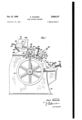
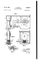
- Figure 1 is a side elevationrof the automatic rimless lens edge grinding machine as seen from the left hand side thereof.
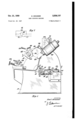
- Figure 2 is a side elevation of the grinding machine shown in Figure 1', as seen'from the right hand side thereof.
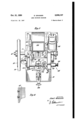
- Figure 3 is a top plan view of the machine shown in Figures 1 and 2.
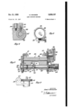
- Figure 4 is a cross-sectional view, the section being taken as on line 4-4 in Figure 3.
- Figure 5 is a cross-sectional view, the section being taken as on line 55 in Figure 2.
- Figure 6 is a cross-sectional view, the section being taken as on line 66 in Figure .3.
- Figure 7 is a wiring diagram of the electric circuit. r
- Figure 8 is a fragmentary cross-sectional view
- Figure 9 is a cross-sectional view, the section being taken as on line 9-9 in Figure 2.
- Figure 10 is a cross-sectional view, the section being taken as on line IGI0 in Figure 9.
- Figure 11 is a cross-sectional view, the section being taken as on line I I--I I in Figure 2.
- Figure 12 is a cross-sectional view, the section being taken as on line I2-l2 in Figure 9.
- Figure 13 is a side view of a fragmentary por tion ofa mounting for a worm and, worm gear which reciprocate the grinding wheel while it rotates.
- the numeral Ill indicates a stationary housing having bearings H in which a drive shaft I2 is rotatably mounted.
- a belt pulley I3 is suitably fixed to the shaft I2 whereby the shaft may be driven by a belt I4.
- a grinding wheel I5 is suitably fixed to the shaft !2. As best shown in Figures 2, 9 and 10 the shaft I2 may during its rotation have limited reciprocatory movements imparted thereto. For imparting reciprocatory movements to the shaft I2 and to the grinding wheel I5, the end of the shaft opposite the pulley I3 is made of smaller diameter to provide a journal for a ball bearing I6.
- a collar II is'mounted on the ball bearing I6 and is held against movement lengthwise of the shaft I2 by a bolt I8 and a washer 20.
- the collar I! has two pins 2
- a vibratory arm 22 is actuated by an adjustable eccentric 23.
- the free end of the arm 22 terminates in a yoke 35 through the opposed arms of which the pins 2
- the adjustable eccentric 23 comprises a rotatable collar 2 3 driven by a shaft 25 ( Figure 12).
- a worm gear 26 is secured to the lower end of the shaft 25.
- the worm gear 26 is in engagement'with a worm 21 fixed to a horizontal shaft 28 mounted in bearings 29.
- a universal joint 38' connects the shaft 28 and a worm gear shaft 3
- the worm gear 32 is in interengagement with a worm 33 on the drive shaft I2.
- the eccentric 23 is integral with a. horizontal slide 36.
- the slide 36 may be adjusted in a guideway 31 in the collar 24 at the upper end of the shaft 25.
- a bushing 39 on the eccentric 23 extends above the arm 22 and may be held in position by a washer 40 and a threaded nut 4
- a slide 42 on the bushing 39 is slidable in close fitting relation in a guideway 43 in the arm 22 and prevents any lost motion during the vibratory movements of the grinding wheel l5.
- Figures 3 and show the mechanism for supporting a lens edgewise against the peripheral surface of the grinding wheel and comprises a rock-frame 45 which is mounted to oscillate on centers 46 in a carrier 41 supported above the grinding wheel I5.
- the rock-frame 45 comprises a shaft 48 having gears 49, 50, fixed thereto at opposite ends.
- the gear 50 is considerably wider than the gear 49.
- the rock-frame 45 also comprises coaxial rotary spindles 5
- carries a fixed collar 53 which contacts a thrust bearing 54.
- the thrust bearing 54 contacts a bearing 55.
- has a gear 56 secured thereto.
- the gear 56 is in interengagement with the gear 49.
- caries a suitable lens holder 59 for a lens 60.
- carries a suitable lens holder 6
- may be in the form of a pad made of rubber, leather, etc., for frictionally engaging the face of the lens to reduce the liability of breakage or marring the lens.
- the lens holders grip the lens from opposite faces of the lens and support the lens in a substantially vertical position.
- the rock-frame 45 has a threaded tubular extension 63 which is coaxial with the spindle 5
- terminates short of the outer end of the extension 63 and contacts a thrust bearing 65.
- the threaded bushing 64 may be rotated to press against the thrust bearing 65 to compress a coil spring 66 on the spindle 5
- the gear 58 is much wider than the gear 62 and this permits considerable movement of the spindle 5
- the gear 62 remains in interengagement with the gear 50 during all such adjustments.
- is thus longitudinally or axially adjustable while the spindle 5
- a template or pattern 6'! of the contour desired of the outer edge of the finished lens 60 is mounted on pins 68 extending from the gear 56.
- the template or pattern 61 has a central aperture 69 to fit on a reduced end portion ll! of the spindle 5
- the end portion H! has a radially movable spring-pressed ball H which is adapted to lock the template 6'! in service position on the spindle 5
- 0 provides a single indicating to the operator when the edge-grinding machine has completed the operation of edge-grinding a lens.
- the electric lamp '15 is lighted by current passing through a fixed electric contact 16 and by a coacting movable electric contact 11 secured to an arm 18.
- the arm 78 is pivotally mounted on a screw 19 in an extension of a micrometer housing 8
- the counterbalanced weight of the rock-frame 45 is supported on the grind stone
- the forward end of the rockframe is raised a distance equal to the difference between the radial distance of the lens 66 to the surface of the wheel l5 and the corresponding radial distance of the template 6! to the point of contact of the template with the table (2. Consequently the arm '18 is lowered so that the contact 11 is separated from the contact I8 and no current flows through either the motor 85 or the lamp 15.
- 5 then continuously rotates it grinds down the edge of the lens, and as this operation proceeds the front end of the rockframe gradually falls.
- Rotation of the lens 61 through a small arc will then bring an unground adjacent portion of the lens into contact with wheel l5 and thus the forward end of the rock-frame will again be raised, thereby permitting the force of the spring 82 to depress the arm 82 and separate the contact 18 from the contact 11, thus opening the circuit through the lamp and motor.
- is thus stopped, whence the continuing rotation of the wheel
- the electric motor 85 has a worm 86 secured to the motor shaft 81.
- the worm 86 is in interengagement with a worm gear 88 which is rotatably mounted in a gear casing 89.
- the casing 89 is secured by screws 90 to the rock-frame 45.
- the gear 88 is fixed to a shaft 9
- has a gear 92 fixed thereon.
- gear 92 is in interengagement with the gear 50 on the shaft 48.
- the casing 89 has a centrally positioned hearing 93 in which the shaft 9
- the gears 49 and 50 are of equal diameter and function as idler gears to transmit motion from the motor driven gear 92 to the spindle gears 56 and 62 which are also of equal diameter.
- This gearing arrangement causes the lens holders 59 and 6
- a counterbalancing weight 95 is secured to an arm 96 extending from the rock-frame 45.
- the weight 95 is adjusted by a screw 91.
- the weight is adjusted on the arm 96 so that the lens 60 will engage the periphery of the grinding wheel I5 with the degree of pressure necessary for the most efiicient grinding effect.
- the adjustable weight 95 functions as means for controlling the pressure of the work on the grinding wheel during the edge-grinding operation.
- a template or pattern 01 of the desired edge contour of the lens is mounted on the reduced end I of the spindle extension I0 and held by the pins 68.
- the spring-pressed ball II is employed to quickly and easily lock the template.
- the lower end of the pin IOI is in engagement with the bearing or journal 52' and when the operating handle 99 is swung to the right against the action of the spring 66, the spindle i and the lens holder 8
- the lens to be cut is properly aligned with the lens holders 59 and 6 I.
- the threaded bushing 64 By adjusting the threaded bushing 64, the lens holder BI is brought into resilient clamping engagement with the lens and with the lens holder 59.
- the counterbalanced rock-frame 45 is released from being held in an upward position by a suitable lock 98 into operative position, whereby the rock-frame 45 moves down to bring the lens into grinding .position with the grinding wheel I 5.
- a receptacle I06 containing water is mounted on the upper portion of the housing I0 and has a suitable delivery tube I01 from which water is supplied to the grinding wheel I5.
- a cutting tool I08 of diamond hardness For truing up the grinding wheel I5 there is provided a cutting tool I08 of diamond hardness.
- the tool I08 may be adjusted to and from the wheel I5 by a threaded member I09, well known in the art.
- a lens edge-grinding machine comprising a frame having a grinding wheel supported therein on a horizontal axis, means for continuously rotating said wheel, a rock-frame pivotally supported on said frame above said wheel on an axis parallel with said wheel'axis, a two-piece spindle comprising a pair of co-axial sections having means normally urging said sections together,v
- said spindle being mounted in said rock-frame forward of said rock-frame axis, lens-gripping means on the juxtaposed ends of said sections for clamping a lens between said sections, said lens-gripping means being positioned in the plane of said wheel, a member pivoted on a horizontal axis to said frame and extending forward, said spindle having lens template mounting means thereon adapted to hold a lens template thereon co-axial with said spindle, the forward end of said member lying in the same vertical plane as said lens template holding means and hence the same vertical plane as said lens template when said lens template is held on said spindle, said forward end of said member being positioned under said lens template, a fixed electric contact on said frame and a movable electric contact associated therewith on the rear end of said member, resilient means normally urging said rear end of said member downward and hence urging said forward end of said member upward against said lens template and simultaneously urging said movable contact away from said fixed contact, said rock-frame having the forward portion thereof forward of said axis thereof heavier than the rear
Landscapes
- Engineering & Computer Science (AREA)
- Chemical & Material Sciences (AREA)
- Ceramic Engineering (AREA)
- Inorganic Chemistry (AREA)
- Mechanical Engineering (AREA)
- Grinding And Polishing Of Tertiary Curved Surfaces And Surfaces With Complex Shapes (AREA)
Description
Oct. 31', 1950 E. GRASSER LENS GRINDING MACHINE -5 Sheets-Sheet 1 Filed 001:. 22. 1947 INVENTOR. Emil Grasser BY 3 K 2 ATTOBNZE'Y Oct. 31, 1950 R ss 2,528,137
LENS GRINDING MACHINE Filed 001;. 22. 1947 5 Sheets-Sheet 2 1N VEN TOR. 3 /2712 Grasser ATTORNEY E- GRASSER LENS GRINDING MACHINE Oct. 31, 1950 5 Sheets-Sheet 3 Filed Oct. 22. 1947 INVENTOR. 1 /1! Grass?!" g ATTORNEY Oct 31, 1950 E. G AssE 2,528,137
LENS GRINDING MACHINE Filed Oct. 22. 1947 5 Sheets-Sheet 4 I INVENTOR. 71212 fire-519e Oct. 31, 1950 E. GRASSER 2,528,137
LENS GRINDING MACHINE Filed Oct. 22. 1947 5 Sheets-Sheet 5 INVENTOR. 24 7111! firaas'er Patented Oct. 31, 1950 UNITED STATES PATENT OFFICE LENS GRINDING MACHINE Emil Grasser, Brooklyn, N. Y. Application October 22, 1947, Serial No. 781,288
1 Claim. 1
This invention relates to lens grinding machines and an object of this invention is to provide a fully automatic rimless lens edger which will grind all shapes and sizes of lenses, without requiring an attendant during operation.
Another object of this invention is to provide a lens edge-grinding machine having two lens clamp members for resilientl clamping and rotating a lens to be edge-ground, and having means for automatically reciprocating a grinding wheel during its rotation to prevent flaking or chipping of the edges of the lenses being ground.
Another object of this invention is to provide two coaxially mounted lens holding spindles driven from a single source of power, the spindles being resiliently pressed toward each other andto provide a thrust bearing on each spindle to cushion vibrational shocks on each side of said lens as an aid in preventing flaking of the lens.
Another object of this invention is to mount a template or pattern having the desired edge contour of the lens at one end of a lens holding spindle and to provide mechanism whereby rotation of the template will cause the lens to be accuratel edge-ground, the mechanism also causing an electric lamp to be lighted when the grinding of the edge of a lens is completed.
With the above and other objects in view, the invention will be hereinafter more particularly described, and the combination and arrangement of parts will be shown in the accompanying drawings and pointed out in the claims which form part of this specification.
Reference will now be had to the drawings, wherein like numerals of reference designate corresponding parts throughout the several views, in which:
Figure 1 is a side elevationrof the automatic rimless lens edge grinding machine as seen from the left hand side thereof.
Figure 2 is a side elevation of the grinding machine shown in Figure 1', as seen'from the right hand side thereof.
Figure 3 is a top plan view of the machine shown in Figures 1 and 2. V
Figure 4 is a cross-sectional view, the section being taken as on line 4-4 in Figure 3.
Figure 5 is a cross-sectional view, the section being taken as on line 55 in Figure 2.
Figure 6 is a cross-sectional view, the section being taken as on line 66 in Figure .3.
Figure 7 is a wiring diagram of the electric circuit. r
Figure 8 is a fragmentary cross-sectional view,
2 the section being taken as on line Figure 3.
Figure 9 is a cross-sectional view, the section being taken as on line 9-9 in Figure 2.
Figure 10 is a cross-sectional view, the section being taken as on line IGI0 in Figure 9.
Figure 11 is a cross-sectional view, the section being taken as on line I I--I I in Figure 2.
Figure 12 is a cross-sectional view, the section being taken as on line I2-l2 in Figure 9.
Figure 13 is a side view of a fragmentary por tion ofa mounting for a worm and, worm gear which reciprocate the grinding wheel while it rotates.
In the illustrated embodiment of the invention, the numeral Ill indicates a stationary housing having bearings H in which a drive shaft I2 is rotatably mounted. A belt pulley I3 is suitably fixed to the shaft I2 whereby the shaft may be driven by a belt I4.
A grinding wheel I5 is suitably fixed to the shaft !2. As best shown in Figures 2, 9 and 10 the shaft I2 may during its rotation have limited reciprocatory movements imparted thereto. For imparting reciprocatory movements to the shaft I2 and to the grinding wheel I5, the end of the shaft opposite the pulley I3 is made of smaller diameter to provide a journal for a ball bearing I6. A collar II is'mounted on the ball bearing I6 and is held against movement lengthwise of the shaft I2 by a bolt I8 and a washer 20. The collar I! has two pins 2| extending diametrically therefrom.
A vibratory arm 22 is actuated by an adjustable eccentric 23. The free end of the arm 22 terminates in a yoke 35 through the opposed arms of which the pins 2| freely pass. The adjustable eccentric 23 comprises a rotatable collar 2 3 driven by a shaft 25 (Figure 12). A worm gear 26 is secured to the lower end of the shaft 25. The worm gear 26 is in engagement'with a worm 21 fixed to a horizontal shaft 28 mounted in bearings 29.
A universal joint 38'connects the shaft 28 and a worm gear shaft 3| having a worm gear 32 fixed thereto. The worm gear 32 is in interengagement with a worm 33 on the drive shaft I2. 3
It will thus beseen that rotation'" of the drive shaft I2 will cause rotation of the shaft 28 and the shaft 25 and the adjustable eccentric 23. The eccentric 23 imparts vibratory movements to the arm 22 about a pivot 34; and, through the yoke 35, vibratory 'movements are imparted to the drive shaft I2 and to the grinding Wheel I5 secured thereon.
As shown in Figure 12, it will be seen that the eccentric 23 is integral with a. horizontal slide 36. The slide 36 may be adjusted in a guideway 31 in the collar 24 at the upper end of the shaft 25.
A bushing 39 on the eccentric 23 extends above the arm 22 and may be held in position by a washer 40 and a threaded nut 4|. It is thus pos sible to change the position of the eccentric 23 with relation to the shaft 25 and vary the amplitude of the vibratory movements of the grinding wheel l5.
A slide 42 on the bushing 39 is slidable in close fitting relation in a guideway 43 in the arm 22 and prevents any lost motion during the vibratory movements of the grinding wheel l5.
Figures 3 and show the mechanism for supporting a lens edgewise against the peripheral surface of the grinding wheel and comprises a rock-frame 45 which is mounted to oscillate on centers 46 in a carrier 41 supported above the grinding wheel I5.
The rock-frame 45 comprises a shaft 48 having gears 49, 50, fixed thereto at opposite ends. The gear 50 is considerably wider than the gear 49. The rock-frame 45 also comprises coaxial rotary spindles 5|, 5| which are journaled in bearings 52, 52' provided in the outer portion of the rockframe. 4
The spindle 5| carries a fixed collar 53 which contacts a thrust bearing 54. The thrust bearing 54 contacts a bearing 55. The spindle 5| has a gear 56 secured thereto. The gear 56 is in interengagement with the gear 49. At its free end, the spindle 5| caries a suitable lens holder 59 for a lens 60.
The spindle 5| carries a suitable lens holder 6| at its free end and has a gear 62 fixed thereto and in engagement with the gear 50. The lens holder 6| may be in the form of a pad made of rubber, leather, etc., for frictionally engaging the face of the lens to reduce the liability of breakage or marring the lens. The lens holders grip the lens from opposite faces of the lens and support the lens in a substantially vertical position.
The rock-frame 45 has a threaded tubular extension 63 which is coaxial with the spindle 5| and has a bushing 64 threaded therein. The spindle 5| terminates short of the outer end of the extension 63 and contacts a thrust bearing 65.
The threaded bushing 64 may be rotated to press against the thrust bearing 65 to compress a coil spring 66 on the spindle 5| and releasably clamp the lens Bil between the lens holders 59 and 6|. It is to be noted that the gear 58 is much wider than the gear 62 and this permits considerable movement of the spindle 5| from the spindle 5| for inserting or removing the lens 611 from the rock-frame 45. The gear 62 remains in interengagement with the gear 50 during all such adjustments. The spindle 5| is thus longitudinally or axially adjustable while the spindle 5| is not adjustable longitudinally or axially.
A template or pattern 6'! of the contour desired of the outer edge of the finished lens 60 is mounted on pins 68 extending from the gear 56. The template or pattern 61 has a central aperture 69 to fit on a reduced end portion ll! of the spindle 5|. The end portion H! has a radially movable spring-pressed ball H which is adapted to lock the template 6'! in service position on the spindle 5|. Upon rotation of the template 57, its outer edges successively contact a table 72 which is fixed by a bolt 13 to an arm 14 and which is normally urged against the template by a coiled spring 82, as will become clearer below. The arm 14 is suitably mounted for vertical adjustment by a micrometer dial 80.
As shown in Figures 1 and 2, an electric lamp 15 suitably mounted on the frame |0 provides a single indicating to the operator when the edge-grinding machine has completed the operation of edge-grinding a lens. The electric lamp '15 is lighted by current passing through a fixed electric contact 16 and by a coacting movable electric contact 11 secured to an arm 18. The arm 78 is pivotally mounted on a screw 19 in an extension of a micrometer housing 8|.
When the edge of a lens 60 is ground to a finish according to the contour of a portion of the template 61, the weight of the rock-frame causes the table 12 and the micro-meter housing 8| to pivot about the screw 19 and to raise the arm 18 against the force of the compression spring 82 and bring the contact I1 against the stationary contact 16, thereby closing the circuit through the lamp 15 and the motor 85 (Figure '7) from a source of electric energy not shown.
The counterbalanced weight of the rock-frame 45 is supported on the grind stone |5 by the lens 60, which at the beginning of the grinding operation has every radial dimension greater than every corresponding radial dimension of the template 61. Thus the forward end of the rockframe is raised a distance equal to the difference between the radial distance of the lens 66 to the surface of the wheel l5 and the corresponding radial distance of the template 6! to the point of contact of the template with the table (2. Consequently the arm '18 is lowered so that the contact 11 is separated from the contact I8 and no current flows through either the motor 85 or the lamp 15. As the wheel |5 then continuously rotates it grinds down the edge of the lens, and as this operation proceeds the front end of the rockframe gradually falls. When the lens has been ground to the point where the above difference between the radial distances mentioned is zero, then the weight of the rock-frame will begin to be transferred partly to the table 12 through the template 61, and owing to the small distance between the contacts 16, H, a very small additional amount of grinding of the lens will cause the template to press down the table 12 a distance sufficient to raise the arm 18 sufficiently to bring the contact 18 against the contact 11. This closes the circuit (Fig. 7) through the lamp 15 and the motor 85, whence the lamp glows and the motor begins to rotate. Rotation of the motor 85, as is obvious, will rotate the shaft 5|, 5| and hence the lens 66 and the template 61.
Rotation of the lens 61 through a small arc will then bring an unground adjacent portion of the lens into contact with wheel l5 and thus the forward end of the rock-frame will again be raised, thereby permitting the force of the spring 82 to depress the arm 82 and separate the contact 18 from the contact 11, thus opening the circuit through the lamp and motor. Rotation of the shaft 5|, 5| is thus stopped, whence the continuing rotation of the wheel |5 will begin grinding down the newly presented edge of the lens until again the radial distance at the newly presented point on the edge of the lens is reduced to the corresponding radial distance of the template to the table 12, as above set forth. This performance is then repeated until the entire periphery of the lens 66 has been ground down to the shape and dimensions of the template 61, at
which time, as is obvious, the switch 11, I8 will remain closed so that the shaft 5|, 5| rotates continuously and the lamp I5 remains uninterruptedly energized, giving a signal to the operator that the grinding of the lens has been completed.
The electric motor 85 has a worm 86 secured to the motor shaft 81. The worm 86 is in interengagement with a worm gear 88 which is rotatably mounted in a gear casing 89. The casing 89 is secured by screws 90 to the rock-frame 45.
The gear 88 is fixed to a shaft 9| (Figure 5).
The shaft 9| has a gear 92 fixed thereon. The
gear 92 is in interengagement with the gear 50 on the shaft 48.
The casing 89 has a centrally positioned hearing 93 in which the shaft 9| is rotatably mounted. The gears 49 and 50 are of equal diameter and function as idler gears to transmit motion from the motor driven gear 92 to the spindle gears 56 and 62 which are also of equal diameter.
This gearing arrangement causes the lens holders 59 and 6| to be rotated by a single source of power in the same direction and with equal speed.
A counterbalancing weight 95 is secured to an arm 96 extending from the rock-frame 45. The weight 95 is adjusted by a screw 91. The weight is adjusted on the arm 96 so that the lens 60 will engage the periphery of the grinding wheel I5 with the degree of pressure necessary for the most efiicient grinding effect. The adjustable weight 95 functions as means for controlling the pressure of the work on the grinding wheel during the edge-grinding operation.
A template or pattern 01 of the desired edge contour of the lens is mounted on the reduced end I of the spindle extension I0 and held by the pins 68. The spring-pressed ball II is employed to quickly and easily lock the template.
The operator then swings an operating or lens releasing handle 99 to the right about a pivot I 00 (Figure 6). This movement causes swinging movement of a pin IOI fixed in the handle 99 and slidable in a slot I02 in the upper portion of the rock-frame 45.
It is to be noted that the lower end of the pin IOI is in engagement with the bearing or journal 52' and when the operating handle 99 is swung to the right against the action of the spring 66, the spindle i and the lens holder 8| are moved away from the lens holder 59 to permit inserting a lens therebetween.
The lens to be cut is properly aligned with the lens holders 59 and 6 I. By adjusting the threaded bushing 64, the lens holder BI is brought into resilient clamping engagement with the lens and with the lens holder 59.
The counterbalanced rock-frame 45 is released from being held in an upward position by a suitable lock 98 into operative position, whereby the rock-frame 45 moves down to bring the lens into grinding .position with the grinding wheel I 5.
A receptacle I06 containing water is mounted on the upper portion of the housing I0 and has a suitable delivery tube I01 from which water is supplied to the grinding wheel I5.
For truing up the grinding wheel I5 there is provided a cutting tool I08 of diamond hardness.
The tool I08 may be adjusted to and from the wheel I5 by a threaded member I09, well known in the art.
In accordance with the patent statutes I have described and illustrated the preferred embodiments of my invention, but it will be understood that various changes and modifications can be made therein without departing from the spirit of the invention as defined by the appended claim.
I claim: 7
A lens edge-grinding machine comprising a frame having a grinding wheel supported therein on a horizontal axis, means for continuously rotating said wheel, a rock-frame pivotally supported on said frame above said wheel on an axis parallel with said wheel'axis, a two-piece spindle comprising a pair of co-axial sections having means normally urging said sections together,v
said spindle being mounted in said rock-frame forward of said rock-frame axis, lens-gripping means on the juxtaposed ends of said sections for clamping a lens between said sections, said lens-gripping means being positioned in the plane of said wheel, a member pivoted on a horizontal axis to said frame and extending forward, said spindle having lens template mounting means thereon adapted to hold a lens template thereon co-axial with said spindle, the forward end of said member lying in the same vertical plane as said lens template holding means and hence the same vertical plane as said lens template when said lens template is held on said spindle, said forward end of said member being positioned under said lens template, a fixed electric contact on said frame and a movable electric contact associated therewith on the rear end of said member, resilient means normally urging said rear end of said member downward and hence urging said forward end of said member upward against said lens template and simultaneously urging said movable contact away from said fixed contact, said rock-frame having the forward portion thereof forward of said axis thereof heavier than the rearward portion thereof so that said forward portion is normally urged by gravity toward saidwheel, said lens having every dimension thereof passing through the axis thereof greater than the diameter of said spindle whereby said lens normally rests on said wheel and supports said rock-frame, an electric motor, gear means connecting said motor with said spindle for rotating said spindle upon energization of said motor, said motor being adapted to be connected in an electrical circuit including said electric contacts whereby mutual engagement of said contacts closes said circuit through said motor. EMIL GRASSER.
REFERENCES CITED 7 The following references are of record in the file of this patent:
UNITED STATES PATENTS Jackson Aug. 27, 1946
Priority Applications (1)
| Application Number | Priority Date | Filing Date | Title |
|---|---|---|---|
| US781288A US2528137A (en) | 1947-10-22 | 1947-10-22 | Lens grinding machine |
Applications Claiming Priority (1)
| Application Number | Priority Date | Filing Date | Title |
|---|---|---|---|
| US781288A US2528137A (en) | 1947-10-22 | 1947-10-22 | Lens grinding machine |
Publications (1)
| Publication Number | Publication Date |
|---|---|
| US2528137A true US2528137A (en) | 1950-10-31 |
Family
ID=25122262
Family Applications (1)
| Application Number | Title | Priority Date | Filing Date |
|---|---|---|---|
| US781288A Expired - Lifetime US2528137A (en) | 1947-10-22 | 1947-10-22 | Lens grinding machine |
Country Status (1)
| Country | Link |
|---|---|
| US (1) | US2528137A (en) |
Cited By (5)
| Publication number | Priority date | Publication date | Assignee | Title |
|---|---|---|---|---|
| US2618106A (en) * | 1950-10-06 | 1952-11-18 | Shuron Optical Co Inc | Booster for lens edge grinding machines |
| US2651890A (en) * | 1951-12-11 | 1953-09-15 | Rubinstein Robert | Automatic edge grinding machine for lenses |
| US2725689A (en) * | 1951-09-13 | 1955-12-06 | Super Cut | Apparatus for grinding the edges of eyeglass lenses and like workpieces |
| US2821050A (en) * | 1954-09-29 | 1958-01-28 | Shuron Optical Co Inc | Edge grinding machine for lenses |
| US3210890A (en) * | 1962-08-03 | 1965-10-12 | Edgar J Schroth | Edging machine |
Citations (12)
| Publication number | Priority date | Publication date | Assignee | Title |
|---|---|---|---|---|
| US681396A (en) * | 1899-09-25 | 1901-08-27 | Max Jungnickel | Machine for grinding facets on glasses for spectacles. |
| US739264A (en) * | 1902-11-19 | 1903-09-15 | Eli M Long | Lens-grinding machine. |
| US927949A (en) * | 1908-06-03 | 1909-07-13 | Standard Optical Co | Lens-grinding machine. |
| US1051869A (en) * | 1910-12-24 | 1913-02-04 | Seyboth & Company | Machine for grinding spectacle and other glasses.. |
| US1610638A (en) * | 1925-05-19 | 1926-12-14 | Walter E White | Edge-grinding machine |
| US1659560A (en) * | 1921-09-17 | 1928-02-21 | Bausch & Lomb | Lens-grinding machine |
| US2164155A (en) * | 1938-12-22 | 1939-06-27 | Lemay Arthur | Automatic grinding device |
| US2175719A (en) * | 1937-10-02 | 1939-10-10 | Shuron Optical Co Inc | Lens edging machine |
| US2233312A (en) * | 1939-08-23 | 1941-02-25 | Herman Pollack | Grinding machine |
| US2321383A (en) * | 1940-09-28 | 1943-06-08 | American Optical Corp | Contour forming apparatus |
| US2357154A (en) * | 1943-04-17 | 1944-08-29 | Wilhelm Paul | Lens grinding machine |
| US2406606A (en) * | 1943-05-21 | 1946-08-27 | American Optical Corp | Edging machine |
-
1947
- 1947-10-22 US US781288A patent/US2528137A/en not_active Expired - Lifetime
Patent Citations (12)
| Publication number | Priority date | Publication date | Assignee | Title |
|---|---|---|---|---|
| US681396A (en) * | 1899-09-25 | 1901-08-27 | Max Jungnickel | Machine for grinding facets on glasses for spectacles. |
| US739264A (en) * | 1902-11-19 | 1903-09-15 | Eli M Long | Lens-grinding machine. |
| US927949A (en) * | 1908-06-03 | 1909-07-13 | Standard Optical Co | Lens-grinding machine. |
| US1051869A (en) * | 1910-12-24 | 1913-02-04 | Seyboth & Company | Machine for grinding spectacle and other glasses.. |
| US1659560A (en) * | 1921-09-17 | 1928-02-21 | Bausch & Lomb | Lens-grinding machine |
| US1610638A (en) * | 1925-05-19 | 1926-12-14 | Walter E White | Edge-grinding machine |
| US2175719A (en) * | 1937-10-02 | 1939-10-10 | Shuron Optical Co Inc | Lens edging machine |
| US2164155A (en) * | 1938-12-22 | 1939-06-27 | Lemay Arthur | Automatic grinding device |
| US2233312A (en) * | 1939-08-23 | 1941-02-25 | Herman Pollack | Grinding machine |
| US2321383A (en) * | 1940-09-28 | 1943-06-08 | American Optical Corp | Contour forming apparatus |
| US2357154A (en) * | 1943-04-17 | 1944-08-29 | Wilhelm Paul | Lens grinding machine |
| US2406606A (en) * | 1943-05-21 | 1946-08-27 | American Optical Corp | Edging machine |
Cited By (5)
| Publication number | Priority date | Publication date | Assignee | Title |
|---|---|---|---|---|
| US2618106A (en) * | 1950-10-06 | 1952-11-18 | Shuron Optical Co Inc | Booster for lens edge grinding machines |
| US2725689A (en) * | 1951-09-13 | 1955-12-06 | Super Cut | Apparatus for grinding the edges of eyeglass lenses and like workpieces |
| US2651890A (en) * | 1951-12-11 | 1953-09-15 | Rubinstein Robert | Automatic edge grinding machine for lenses |
| US2821050A (en) * | 1954-09-29 | 1958-01-28 | Shuron Optical Co Inc | Edge grinding machine for lenses |
| US3210890A (en) * | 1962-08-03 | 1965-10-12 | Edgar J Schroth | Edging machine |
Similar Documents
| Publication | Publication Date | Title |
|---|---|---|
| US2806327A (en) | Lens grinder | |
| US2321383A (en) | Contour forming apparatus | |
| GB580110A (en) | Improvements in and relating to the grinding and polishing of lenses | |
| US3145506A (en) | Contact lens contouring and polishing machine | |
| US2087687A (en) | Apparatus for producing one-piece multifocal ophthalmic lenses | |
| US2528137A (en) | Lens grinding machine | |
| GB663815A (en) | Improvements in grinding machines | |
| GB1497129A (en) | Ultrasonic lapping apparatus for drawing dies | |
| US2175719A (en) | Lens edging machine | |
| US2056149A (en) | Truing apparatus | |
| US1733098A (en) | Centerless grinding machine | |
| US819628A (en) | Jewel grinding and polishing machine. | |
| US2498012A (en) | Grinding machine | |
| US2642703A (en) | Grinding wheel-speed control | |
| US1309264A (en) | Machine foe | |
| US2137821A (en) | Grinding machine | |
| US1639958A (en) | Centerless grinding machine | |
| US2616226A (en) | Apparatus for abrading | |
| US1651532A (en) | Lens-edging machine | |
| US900664A (en) | Lens-grinding machine. | |
| US1475626A (en) | Lens-tool-grinding machine | |
| US1467518A (en) | Grinding machine | |
| US737313A (en) | Lens-grinding machine. | |
| US2179088A (en) | Lens abrading machine | |
| US2326661A (en) | Truing apparatus |