US2527648A - Method and machine for making inlaid linoleum - Google Patents
Method and machine for making inlaid linoleum Download PDFInfo
- Publication number
- US2527648A US2527648A US58827A US5882748A US2527648A US 2527648 A US2527648 A US 2527648A US 58827 A US58827 A US 58827A US 5882748 A US5882748 A US 5882748A US 2527648 A US2527648 A US 2527648A
- Authority
- US
- United States
- Prior art keywords
- web
- machine
- linoleum
- pattern
- components
- Prior art date
- Legal status (The legal status is an assumption and is not a legal conclusion. Google has not performed a legal analysis and makes no representation as to the accuracy of the status listed.)
- Expired - Lifetime
Links
- 238000000034 method Methods 0.000 title description 11
- 239000000203 mixture Substances 0.000 description 40
- 230000007246 mechanism Effects 0.000 description 22
- 230000033001 locomotion Effects 0.000 description 21
- 239000003292 glue Substances 0.000 description 18
- 238000003825 pressing Methods 0.000 description 16
- 238000005520 cutting process Methods 0.000 description 15
- 239000000463 material Substances 0.000 description 14
- 239000011435 rock Substances 0.000 description 9
- VLCQZHSMCYCDJL-UHFFFAOYSA-N tribenuron methyl Chemical compound COC(=O)C1=CC=CC=C1S(=O)(=O)NC(=O)N(C)C1=NC(C)=NC(OC)=N1 VLCQZHSMCYCDJL-UHFFFAOYSA-N 0.000 description 9
- 238000004519 manufacturing process Methods 0.000 description 8
- 239000000853 adhesive Substances 0.000 description 7
- 230000001070 adhesive effect Effects 0.000 description 7
- 238000007599 discharging Methods 0.000 description 6
- 238000010276 construction Methods 0.000 description 3
- 229910000831 Steel Inorganic materials 0.000 description 2
- 239000011248 coating agent Substances 0.000 description 2
- 238000000576 coating method Methods 0.000 description 2
- 230000006835 compression Effects 0.000 description 2
- 238000007906 compression Methods 0.000 description 2
- 239000004744 fabric Substances 0.000 description 2
- 239000010959 steel Substances 0.000 description 2
- 235000009467 Carica papaya Nutrition 0.000 description 1
- 240000006432 Carica papaya Species 0.000 description 1
- 230000000712 assembly Effects 0.000 description 1
- 238000000429 assembly Methods 0.000 description 1
- 239000004568 cement Substances 0.000 description 1
- 238000000151 deposition Methods 0.000 description 1
- 230000005484 gravity Effects 0.000 description 1
- 235000000396 iron Nutrition 0.000 description 1
- 239000002648 laminated material Substances 0.000 description 1
- 235000021388 linseed oil Nutrition 0.000 description 1
- 239000000944 linseed oil Substances 0.000 description 1
- 238000012423 maintenance Methods 0.000 description 1
- 239000003921 oil Substances 0.000 description 1
- 235000019198 oils Nutrition 0.000 description 1
- 239000004033 plastic Substances 0.000 description 1
- 239000011120 plywood Substances 0.000 description 1
- 230000003014 reinforcing effect Effects 0.000 description 1
- 238000007789 sealing Methods 0.000 description 1
- 230000035939 shock Effects 0.000 description 1
- 238000006467 substitution reaction Methods 0.000 description 1
- 230000001360 synchronised effect Effects 0.000 description 1
- 239000002699 waste material Substances 0.000 description 1
Images


Classifications
-
- D—TEXTILES; PAPER
- D06—TREATMENT OF TEXTILES OR THE LIKE; LAUNDERING; FLEXIBLE MATERIALS NOT OTHERWISE PROVIDED FOR
- D06N—WALL, FLOOR, OR LIKE COVERING MATERIALS, e.g. LINOLEUM, OILCLOTH, ARTIFICIAL LEATHER, ROOFING FELT, CONSISTING OF A FIBROUS WEB COATED WITH A LAYER OF MACROMOLECULAR MATERIAL; FLEXIBLE SHEET MATERIAL NOT OTHERWISE PROVIDED FOR
- D06N7/00—Flexible sheet materials not otherwise provided for, e.g. textile threads, filaments, yarns or tow, glued on macromolecular material
- D06N7/0005—Floor covering on textile basis comprising a fibrous substrate being coated with at least one layer of a polymer on the top surface
- D06N7/0028—Floor covering on textile basis comprising a fibrous substrate being coated with at least one layer of a polymer on the top surface characterised by colour effects, e.g. craquelé, reducing gloss
-
- Y—GENERAL TAGGING OF NEW TECHNOLOGICAL DEVELOPMENTS; GENERAL TAGGING OF CROSS-SECTIONAL TECHNOLOGIES SPANNING OVER SEVERAL SECTIONS OF THE IPC; TECHNICAL SUBJECTS COVERED BY FORMER USPC CROSS-REFERENCE ART COLLECTIONS [XRACs] AND DIGESTS
- Y10—TECHNICAL SUBJECTS COVERED BY FORMER USPC
- Y10T—TECHNICAL SUBJECTS COVERED BY FORMER US CLASSIFICATION
- Y10T156/00—Adhesive bonding and miscellaneous chemical manufacture
- Y10T156/10—Methods of surface bonding and/or assembly therefor
- Y10T156/1052—Methods of surface bonding and/or assembly therefor with cutting, punching, tearing or severing
- Y10T156/1082—Partial cutting bonded sandwich [e.g., grooving or incising]
-
- Y—GENERAL TAGGING OF NEW TECHNOLOGICAL DEVELOPMENTS; GENERAL TAGGING OF CROSS-SECTIONAL TECHNOLOGIES SPANNING OVER SEVERAL SECTIONS OF THE IPC; TECHNICAL SUBJECTS COVERED BY FORMER USPC CROSS-REFERENCE ART COLLECTIONS [XRACs] AND DIGESTS
- Y10—TECHNICAL SUBJECTS COVERED BY FORMER USPC
- Y10T—TECHNICAL SUBJECTS COVERED BY FORMER US CLASSIFICATION
- Y10T156/00—Adhesive bonding and miscellaneous chemical manufacture
- Y10T156/10—Methods of surface bonding and/or assembly therefor
- Y10T156/1089—Methods of surface bonding and/or assembly therefor of discrete laminae to single face of additional lamina
- Y10T156/1092—All laminae planar and face to face
- Y10T156/1097—Lamina is running length web
-
- Y—GENERAL TAGGING OF NEW TECHNOLOGICAL DEVELOPMENTS; GENERAL TAGGING OF CROSS-SECTIONAL TECHNOLOGIES SPANNING OVER SEVERAL SECTIONS OF THE IPC; TECHNICAL SUBJECTS COVERED BY FORMER USPC CROSS-REFERENCE ART COLLECTIONS [XRACs] AND DIGESTS
- Y10—TECHNICAL SUBJECTS COVERED BY FORMER USPC
- Y10T—TECHNICAL SUBJECTS COVERED BY FORMER US CLASSIFICATION
- Y10T156/00—Adhesive bonding and miscellaneous chemical manufacture
- Y10T156/12—Surface bonding means and/or assembly means with cutting, punching, piercing, severing or tearing
-
- Y—GENERAL TAGGING OF NEW TECHNOLOGICAL DEVELOPMENTS; GENERAL TAGGING OF CROSS-SECTIONAL TECHNOLOGIES SPANNING OVER SEVERAL SECTIONS OF THE IPC; TECHNICAL SUBJECTS COVERED BY FORMER USPC CROSS-REFERENCE ART COLLECTIONS [XRACs] AND DIGESTS
- Y10—TECHNICAL SUBJECTS COVERED BY FORMER USPC
- Y10T—TECHNICAL SUBJECTS COVERED BY FORMER US CLASSIFICATION
- Y10T156/00—Adhesive bonding and miscellaneous chemical manufacture
- Y10T156/17—Surface bonding means and/or assemblymeans with work feeding or handling means
- Y10T156/1702—For plural parts or plural areas of single part
- Y10T156/1712—Indefinite or running length work
- Y10T156/1722—Means applying fluent adhesive or adhesive activator material between layers
- Y10T156/1724—At spaced areas
-
- Y—GENERAL TAGGING OF NEW TECHNOLOGICAL DEVELOPMENTS; GENERAL TAGGING OF CROSS-SECTIONAL TECHNOLOGIES SPANNING OVER SEVERAL SECTIONS OF THE IPC; TECHNICAL SUBJECTS COVERED BY FORMER USPC CROSS-REFERENCE ART COLLECTIONS [XRACs] AND DIGESTS
- Y10—TECHNICAL SUBJECTS COVERED BY FORMER USPC
- Y10T—TECHNICAL SUBJECTS COVERED BY FORMER US CLASSIFICATION
- Y10T156/00—Adhesive bonding and miscellaneous chemical manufacture
- Y10T156/17—Surface bonding means and/or assemblymeans with work feeding or handling means
- Y10T156/1702—For plural parts or plural areas of single part
- Y10T156/1712—Indefinite or running length work
- Y10T156/1734—Means bringing articles into association with web
-
- Y—GENERAL TAGGING OF NEW TECHNOLOGICAL DEVELOPMENTS; GENERAL TAGGING OF CROSS-SECTIONAL TECHNOLOGIES SPANNING OVER SEVERAL SECTIONS OF THE IPC; TECHNICAL SUBJECTS COVERED BY FORMER USPC CROSS-REFERENCE ART COLLECTIONS [XRACs] AND DIGESTS
- Y10—TECHNICAL SUBJECTS COVERED BY FORMER USPC
- Y10T—TECHNICAL SUBJECTS COVERED BY FORMER US CLASSIFICATION
- Y10T156/00—Adhesive bonding and miscellaneous chemical manufacture
- Y10T156/19—Delaminating means
- Y10T156/1961—Severing delaminating means [e.g., chisel, etc.]
- Y10T156/1967—Cutting delaminating means
Definitions
- the present invention relates .to fabric manuiacturing and more particularly to a method and apparatus for making inlaid linoleum.
- Inlaid linoleum as heretofore manufactured is formed from a plurality of individually preshaped plastic components, each generally 01 uniform color throughout its exposed area, and manually placed according to a selected pattern upon a backing sheet of burlap, felt or other material, and to which each is adhesively secured. Thus, with all components in place, an over-all inlaid pattern is provided in the finished fabric.
- Components of the type used for linoleum manufacture are relatively thin and non-rigid and therefore are easily mutilated in handling and subject to shape variation, so that proper registration with adjacent, previously placed, components is a tedious and exacting operation even by hand and where attempted by machinery as in the past has materially increased the difllculties of producing an even properly fitted pattern.
- Fig. 1 represents diagrammatically the several stage operations of the machine;
- Fig. 2 represents a plan of the backing web and linoleum mix thereon as it appears after the operations at stages B, C, D, E, and F;
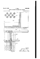
- Fig. 3 represents the working face of the platen for applying glue in the configuration of the selected key pattern;
- Fig. 4 represents the working face of the pressing and cutting platen;
- Fig. 5 represents a section on line 5-5 of Fig. 3;
- Fig. '6 represents a section on line 6-6 of Fig. 4;
- Fig. 7 represents a detail on an enlarged scale of any of the mounted cutting blades;
- Fig. 1 represents diagrammatically the several stage operations of the machine;
- Fig. 2 represents a plan of the backing web and linoleum mix thereon as it appears after the operations at stages B, C, D, E, and F;
- Fig. 3 represents the working face of the platen for applying glue in the configuration of the selected key
- FIG. 8 represents a side elevation of stages'A, B, and C of a linoleum-making machine embodying one form of the present invention
- Fig. 8-A represents a side elevation of the machine as a continuation of Fig. 8 and showing stages D and E
- Fig. 8-13 represents a side elevation of the machine as a continuation of Fig. 8-A showing final stages
- Fig.9 represents a side elevation of stages'A, B, and C of a linoleum-making machine embodying one form of the present invention
- FIG. 8-A represents a side elevation of the machine as a continuation of Fig. 8 and showing stages D and E
- Fig. 8-13 represents a side elevation of the machine as a continuation of Fig. 8-A showing final stages
- Fig. 10 represents a fragmentary plan of the glue receptacle operating means
- Fig. .11 represents a plan of the transfer assemblies of stages D and E
- Fig. 12 represents a side elevation of the transfer assembly of stage D but can also be the assembly for stage E, except in the latter the operating cam is one hundred and eighty degrees out of phase with the same cam of stage D
- Fig. 13 represents a detail in end elevation of the air valve control mechanism
- Fig. 14 represents a section on line I4-I4 of Fig. 13
- Fig. 15 represents an end elevation of the pressing and cutting unit of stage C
- Fig. 16 represents a fragmentary side elevation of the unit of stage C
- Fig. 10 represents a fragmentary side elevation of the unit of stage C
- Fig. 10 represents a fragmentary plan of the glue receptacle operating means
- Fig. .11 represents a plan of the transfer assemblies of stages D and E
- Fig. 12 represents a side elevation of the transfer assembly of stage D but can
- FIG. 17 represents a sectional longitudinal detail of the blade mounting for the unit of Fig. 15 and the related machine bed, web and conveyor part;
- Fig. 18 represents a partial plan of one form of platform locking means;
- Fig. 19 represents a section on line I9-I9 of Fig. 18;
- Fig. 20 represents a sectional side elevation of one of the component trucks, shown on a larger scale;
- Fig. 21 represents a fragmentary end elevation, partly broken away, of the truck of Fig. 20;
- Fig. 22 represents a fragmentary detail in elevation partly broken away, of the suction nozzle assembly on an enlarged scale;
- Fig. 23 represents a fragmentary bottom plan of Fig. 22;
- Fig. 24 represents a detail on a larger scale of the yoke and cam roller construction;
- Fig. 25 represents a detail in side elevation of the step-by-step mechanism; and
- Fig. 26 ranresents a plan of the parts shown in Fig. 25.
- Figs. 1 and 2 the operation of the apparatus and steps of the method are diagrammatically illustrated in Figs. 1 and 2 as introductory to the detailed description, and wherein a backing web III of burlap, felt, or other suitable material is indicated as travelling step by step through. a succession of operating stages.
- the web I is pressed into contact with piercing pins upstanding from two conveyors for feeding the web step by step towards the succeeding stages.
- a printing block having a face shaped in accordance with a selected key pattern, is wiped with glue and then pressed to the web to leave a glue faced pattern.
- thesheet of linoleum mix of selected color is fed above the web and pressed into contact with the key pattern outlined in glue on the web backing, while simultaneously cutter blades sever the mix in the shape of the components which are to be removed when the key pattern reaches stage D.
- the key pattern is now an integral part of the web, the components bounded by it are unattached to the web ready for removal.
- stage D the preshaped severed components are removed and stacked at one side of the machine for use in other patterns instead of being discarded as waste.
- the key pattern consists of the original key pattern with voids, where the unwanted components have been removed, and such components are now replaced at stage E by the proper components to complete the final pattern of the inlay which has been selected.
- stage E the complete inlaid web is delivered to stage F whereby the pattern is pressed into contact with the backing by a heated or cold pressing platen, making ready for the rotary press, at which complete adhesion is secured.
- the web I. is shown entering the machine to seat on a bed II with its side margins respectively above two endless conveyors I2, which run the full length of the machine at each side of the bed II, and are supported by the machine side frames I3.
- the upper face of each conveyor is providedwith a longitudinally disposed row of suitably spaced pins I4 for piercing the web to transmit the desired motion thereto.
- the entering end of the web I0 passes under two transversely connected pressing weights I5, one above each row of pins I4, so that as the weights are released to drop by gravity, the web margin below each weight will be impaled upon the motion-transmitting pins I4 of the respective conveyors.
- the weights I! are respectively actuated by vertically disposed plates I8 sliding in guides Il upon the machine frame and projecting downwardly through such guides to terminate respectively in cam rollers I3.
- the two rollers II ride respectively on side face cams keyed to a shaft 2I transversely disposed between the machine sides, while the contour of the came 20 is preferably such as to lift and release the weights twice during one revolution of the shaft 2 I.
- the cam rollers it drop into the cam dwell depressions so that the weights descend to cause the web to be pierced by the conveyor pins I4. With this accomplished, the next step movement of the web brings it to stage B where it comes to rest momentarily under the vertically reciprocable horizontally disposed block 22.
- the lower face of the block or platen 22 is provided with a cameo pattern 23 of the selected key configuration arranged to be coated with glue, cement, such as linseed oil solution so that when lowered into contact with the upper face of the web it will deposit the glue upon the web in the form of the selected key pattern.
- glue, cement such as linseed oil solution
- the timed movement of the block or platen 22 is obtained by mounting the platen at opposite sides respectively upon slides 24 which ride in vertical guides under the action of lift cams 26 riding under rollers 21 fixed to the respective slides 24 to give the desired platen stroke.
- the cams 26 are fast to a driven shaft 28 which receives its motion in precise timed relation to the step-by-step motion of the web, as will hereinafter be described.
- a spreader roller 30 is provided, the same being rotatably mounted transversely of a glue receptacle 3
- This movement takes place by supporting the receptacle 3I on four vertically adjustable feet 32 which seat respectively in four cups 33, of which each side pair are fixed to a separate slide bar 34 riding respectively in side rails of the machine frame, but supported on rollers 35 journalled upon the frame side rails for free sliding action.
- the vertical adjustment for the feet 32 provides means for bringing the spreader roller 30 into wiping relation with the key pattern upon the juxtaposed face of the platen 22.
- the two slide bars 34 are respectively joined to connecting rods 36 which in turn are interconnected to two rock levers 31 pivoted at 38 to the machine frame and arranged to be reciprocated in unison by a tie rod 39 between them and journalling a cam roller 40 at the center thereof for contact with one face of a cam H which is keyed to the shaft 2I.
- a second cam roller 42 is located at the opposite face of the cam 4I and is journalled upon a transverse tie rod 43 which interconnects two swing arms 44 pivoted at 45 to the respective sides I3 of the machine frame.
- and 43 are connected together by two spaced apart yokes 46, the arrangement being such that the rotation of the cam 4I causes the required re ciprocation of the connecting rods 36 and therefore moves the glue roller 30 across the face of 76 the platen 22, to stop in position for the next cycle when tact.
- the projecting ends of its shaft 6! respectively mounts gears 48 in mesh respectively with gears 68 Journalled exteriorly of the receptacle sides and riding respectively in racks 5
- the gears 56 are rotated to transmit turning of the wiping roller 66 through the body of glue.
- the web l8 leaves the stage B with its upper face now coated with glue in the shape of the key pattern impressed by the action of the platen 22 and rides under and in face contact with the incoming layer 52 of linoleum mix, which rides across an overhead frame 56, and down under a guide roller 64 to meet the step by step advancing web I.
- the roller 54 also causes the mix to be pierced by the pins ll of the conveyors. As shown, this feeding of the mix layer takes place through a roller 55 driven by sprocket and chain 56 from shaft 51, which also transmits motion by chain 58 to the shaft 26.
- the web It with its superposed mix layer 52 is now delivered to stage C.
- stage C The function of stage C is to press and smoothly secure the linoleum mix layer 52 against the glueoutlined key pattern upon the web It to be held also by the conveyor pins ll, while simultaneously severing, from that key pattern, those portions of the mix layer 52 which are not to be a part of the predesigned final inlay pattern.
- the pressing and severing unit at stage C comprises a vertically reciprocable head 59 slidable in side guides 68 and provided at opposite ends respectively with suitable pivoted linkage 6
- the ends of the head 68 project at opposite sides of the machine in the form of relatively heavy pins 63, each fitting in the upper end of a driven yoke 66, the lower end of which encircles an eccentric 65 keyed to a shaft 66 driven through a reduction unit 61 from the main drive shaft 68 by means of pinion 69', gear 65', reduction gear shaft 66', pinion 61', and gear 66' keyed to the shaft 66.
- the contact face of the head 58 is in the form of an annular box-like frame I6, preferably rectangular, extending in assembled condition transversely of the web to provide an opening within which the pressing and severing unit is mounted.
- the bounding margin of the it returns for the next wiping con- .opening is horizontally recessed to seat a steel backing plate H to which a base 12, preferably of laminated material such as plywood is anchored.
- the base 12 is laid oil in a pattern of cuts so spaced and arranged relatively as to form a replica of the same size as the key pattern upon the web.
- the mat 14 is glued to or otherwise fixed to the bottom of the base 12.
- a pressing member 15 of sponge rubber In each space bounded by the blades 16 is a pressing member 15 of sponge rubber, and this projects about a sixteenth of an inch beyond the aforesaid bottom face of themat.
- adjusting bolts 16 are threaded through the frame to engage the respective sides of the base as a means of compressing the base to grip the blades 16.
- a fixed rigid frame is disposed transversely of the machine (stage D) and comprises two interconnected skeleton upright side frames 11 which are spaced apart to straddle a predetermined length of pattern area as it passed therethrough or comes to rest therebetween.
- the length of the frames 11 is greater than three times the width of the web in order to project at opposite sides thereof so that the component pick-up units will alternately assume positions above two stack loading trucks located at opposite sides respectively of the machine.
- These frames 11 form spaced guides for two horizontally disposed beams 18 and I6 extending the length of the frames at opposite inner sides thereof and which are suspended at suitable intervals from pairs of vertically disposed lift rods 66 and 66' which are pivotally connected at their upper ends respectively to bell cranks BI and 6
- the arms 64 and 64 of the respective bell cranks terminate in cam rollers 65 and 65' riding in contact respectively with driven cams 66 and 66'.
- the two rows of cams 66 and 86. are respectively keyed to two horizontally journalled shafts l9 and I9 paralleling opposite outer sides of the frames 11.
- the pattern component lifting means comprises two box units 66 and 68, arranged in side to side relation across the web, and each supported by sets of wheels SI for travel transversely of the pattern web upon the beams 18 and 16'.
- Each box unit has a bottom face area suflicient to extend entirely over that portion of the pattern which is to be brought into position beneath it.
- the aforesaid units 66 and 69 are duplicates and in this description like parts will begiven like reference numerals to avoid needless repetition.
- Two such units are provided and together have a combined length at least twice the width of the web so that one box unit 68 will be over a loading truck 82, when the other 68 is over the pattern in one position of unit travel, while travel in the opposite direction reverses the relation of the units to the web and brings unit 88 over a loading truck 83 when the unit 88 is over the pattern.
- Both box units 88 and 89 are sealed to hold a vacuum and the bottom of each is provided with staggered perforations respectively communicating with rigid suction tubes 34 terminating respectively in flexible bellows type suction head 95.
- the tubes 94 are laterally braced by a plate 88 properly perforated to receive the respective tubes 84.
- the plate 34 viewed from below appears as a multiplicity of suction nozzles 85, preferably spaced three quarters of an inch apart in staggered rows so that when lowered into contact with the mix on the web every severed component will be under one or more of the suction nozzles ready to be lifted out on the upstroke of a box unit.
- the volume of each box unit is reduced to an operating minimum as indicated in dotted lines in F .12.
- a vacuum in the box unit 88 the top thereof is provided with two outlets (Figs. 12 and 13) communicating respectively with two branches 81 of a manifold 88 leading to and communicating with a, cylindrical valve chest I88 from which a suction pipe I8I leads to a motor driven exhaust fan chamber I82 by way of an offset pipe I83 and pivot joint I84.
- This latter I84 allows the pipe IN to follow the movement of the unit 88 as it rises, lowers, and swings laterally.
- the opposite ends thereof are in the form of apertured heads I85 and I88, the apertures being in the form of radially arranged tapered ports I81 and I88, the ports I81, when open communicating with the pipe I8I, while the ports I88 when open communicate with the atmosphere.
- the ports I 81 and I88 are alternately opened and closed. and for that purpose a rock shaft H8 is carried axially of the chest and has two disc valves III and H2 mounted thereon, each externally of the chest head but in close sealing relation.
- the valve III is provided with radially disposed ports H3 of like size, spacing and configuration to the head ports I81, so that in open positions both sets of ports I81 and H3 will be in register for passage of air, but in closed position the ports III will be out of register with the ports I81 so that air is cut off.
- the disc valve H2 is provided with radially arranged ports I I4 of like size, spacing and configuration as the head ports I88, so that in open positions both sets of ports I88 and H4 will be in register to exhaust air from the chest and system but in closed positions the ports will be out of register.
- the valve chest and its associated parts provide for two conditions, either subjecting the system to vacuum or relieving it to the atmosphere.
- the means for doing this comprises an arm I28 keyed to the end of the shaft II8, but extending diametrically opposite to the spring biased arm H5, and carrying a vertically adjustable tappet I2I which in the discharging position of the unit.
- 88 has a position above a fixed stop I22 projecting from the side of the machine. The position of the stop I22 is such that it will be met by the tappet I2I at exactly the time the unit 88 has lowered to drop its carried components upon the platform of the waiting truck.
- valve chest I25 is like valve chest I88 and has the same valve control including exhaust relief tappet, which in this instance engages a stop at the other discharge side of the machine to stack the components upon the second truck 83.
- the meeting ends of the two units are interconnected by two spaced okes I3I .and a cross-head I32, the latter riding vertical in guide slots I29, respectively provided in the yokes I3I.
- the cross-head I32 is suspended by an elongated skeleton frame I33 from a pivot bearing I34 supported at its upper end between the side frames 11.
- the frame I33 is generally of open rectangular shape, the sides of which straddle a cam roller I 35, intermediate its length, which is rotatably carried by a spindle I33 having its ends respectively supported by two rod yokes I31.
- a truck 82 mounted on wheels I44, is rolled into place with its removable top plate I45 beneath and registered with the box unit 88 to form a support for a transfer platform I45 upon which the removed components are to be deposited.
- the top plate I45 is provided with a plurality of perforations I4'I,.having the configuration of the key pattern, in each of which there is an upstanding pin I48, which together form boundaries to support the respective components in stacked relation.
- the plate '5 is seated upon a plurality of angle irons I49 fixed to the truck body and is arranged to be removed with the transfer plate I48, when the latter is filled with the stacks of components.
- the transfer platform I48 is provided with the same number and arrangement of perforations I58 through which the pins project to form the aforesaid ortline boundaries for the removed components, such boundaries conforr..i.:g
- the platform I45 In order that the platform I45 can be lowered step by step as each plane of components is released, it is mounted upon the top of two oppositely disposed channel bars III vertically slidable respectively along the outside of two sides of the truck body, such bars I beingseated respectively upon the upwardly turned ends I52 of two transversely arranged lift beams I53, each of which projects through vertical slots I54 in the truck sides to ride in guide angles I55 fixed to the aforesaid truck sides.
- Each lift beam I53 is carried by two spaced apart links I55 respectively forming a pivotal connection to the upper end of two double link toggles I51, the lower ends of each of which are pivoted at I55 to the truck base I50.
- the intermediate pivotal points of the'toggle respectively mount rollers I5I and I52.
- a right-hand and left-hand threaded feed screw I53 is rotatably mounted between the two toggles in parallel relation thereto, and has two leader nuts, in the form of follower bars I54 and I55 each of a length to engage one roller of each set of toggles.
- the outer face of the roller "I of each of the toggles, while the bar I55 will ride against the" outer face of the roller I52 of each of the toggles. thread of the feed screw I53, while the bar I55 is threaded upon the left-hand threadof the feed screw I53.
- the turning of the screw I53 in one direction will feed the follower bars I54 and I55 together to contract the toggle and elevate the lift bars I53, and when turned in the other direction will separate the bars I54 and I55 to allow the toggle to expand and thus lower the lift bars I53. Since at this stage in the cycle of operations the trucks are being loaded, the toggle will be in contracted position to locate the transfer platform I45 relatively close to the plane of the nozzles 95 when ready to discharge and the screw feeding mechanism is geared to lower the platform step by step by a step distance equal to the thickness of component material.
- this action is carried out by keying a ratchet wheel I55 to the feed screw I53 in position to be engaged by a spring pressed pawl I51, pivotally carried by an arm' I65 swingingly mounted on the unthreaded portion of the screw I53.
- the arm I 55 carries a cam roller I10 biased by a ,coil spring I1I against
- the bar I54 is threaded upon right-hand Thus, the bar I54 will ride against 1o to locate the empty platform I45 correctly component-receiving position.
- v opposite frame uprights I15 are respec tively provided with inwardly fixed tubular keepers I30 respectively alined with horizontally, movable bolts I3I which are operated by a rack.
- stage D the-web,-with its key pattern and voids left by the removed components, is fed to stage E where the action of the suction box unitstakes places in reverse order, namely, pattern components complemental in shape to the voids are pickedup alternately from stacks located at opposite sides of the machine upon trucks like those heretofore described.
- the suction box units takes places in reverse order, namely, pattern components complemental in shape to the voids are pickedup alternately from stacks located at opposite sides of the machine upon trucks like those heretofore described.
- the suction box units takes places in reverse order, namely, pattern components complemental in shape to the voids are pickedup alternately from stacks located at opposite sides of the machine upon trucks like those heretofore described.
- the other suction unit is picking up the top layer of sever al stacks from a truck platform and the op- .eration continues alternately but in reverse to the suction units at stage D.
- It will be underanother pattern length will be below a suction
- cross trusses 222 and 223 are provided.
- a heated platen press 224 reciprocated in proper timed relation with the step-by-step travel of the web.
- This pattern press 224 is generally like the press of stage B and may be operated by a like cam reciprocating means receiving motion from the main shaft 58.
- each is in the form of an endless steel band extending along one side of the machine and travelling around idle roller 225 at one end of the machine and around a driven wheel 226 at the other end of the machine.
- the periphery of each wheel 226 is provided with suitably spaced notches 221 with which lugs 228, fixed to the underside of each conveyor band, are arranged to mesh and thereby propel the band as the wheel turns in a succession of angular steps.
- the lugs 228 are so linearly spaced equally apart that each angular turning of the wheels 228 advances the conveyors a distance of eighteen linear inches.
- the wheels 228 are keyed to a shaft 288 suitably journalled transversely of the main frame of the machine and are arranged to be turned step by step by a ratchet wheel 232 located between the wheels 228 and keyed to the shaft 288 and for actuation by a spring pressed 'pawl 238.
- This pawl 283 is carried by an arm 234 mounted on the shaft 288 as a pivot, one portion of said arm being in the form of a rack gear 235 in mesh with an arcuate rack 238 on the outer face of a rock arm 231 pivoted on a spindle 238 supported from the machine frame.
- Journalled on one side of the rock arm 281 is a cam roller 248 riding upon the face of a cam 24! journalled on a counter shaft 242 and driven through a suitable reduction gearing from the main shaft 88.
- a hub 239 is keyed to the shaft 230 and carries a plurality of radially arranged keepers 243 respectively having V- shaped slots 244 for successive engagement by a bolt 245 having a V-shaped end to enter a slot 244.
- the position of the bolt 245 and the spacing of the keepers 243 is such that in each rest position of the conveyors the bolt 245 can enter one of the keepers 243 to prevent movement of the wheels 228 while stage operations are taking place.
- the bolt 245 is carried by its rock arm 246 which is pivoted on the spindle 238 and receives its locking and unlocking motion by means of a driven cam 241, which rides under a cam roller 248 journalled to the side of the rock arm 246.
- the cam 241 is keyed to the same shaft 242 as the cam 2H, and both cams are operated by the rotation of the shaft 242 which is driven through suitable reduction gears 258 and 251 from the main shaft 68.
- the main shaft 68 runs substantially medially throughout the length of the machine and is arranged to be driven continuously by a motor 252 and pulley belt drive 253 located at a convenient location.
- carrying trucks can be prepared with the new pattern components while the machine is still running off the last of the pattern to be discarded.
- the maximum rate of production is eight feet per minute, while by the machine of this invention the rate of production can be stepped up to thirty feet per minute.
- a machine for making inlaid linoleum the combination of a backing web, means for applying an adhesive to said web in the form of a predetermined key pattern, means to superpose a linoleum mix on said web and key pattern,
- a machine for making inlaid linoleum the combination of a backing web, a sheet of linoleum mix loosely seated upon said web, means platform supported beside the machine having a plurality of upstanding pins arranged to form receivingspaces complemental to the contour of the respective said areas, and means for removing the said areas outlined by said key pattern and discharging said areas respectively into the corresponding spaces defined by said pins.
- a machine in accordance with claim 6 wherein means are provided for lowering said platform step by step as successive areas are added to form a stack confined by said pins.
- means for feeding step by step a backingweb having a linoleum mix on the face thereof, means operative in a rest position of said web for severing predetermined areas of said mix to separate areas of a key pattern from the remaining areas, means operative in a second rest position of said web for removing said remaining areas, and means operative during another rest position of said web for stacking said removed areas at one side of the machine.
- a machine for making inlaid linoleum the combination of means for feeding step by step a backing web having a linoleum mix on the face thereof, means operative in a rest position of said web for severing predetermined areas of said mix to separate areas of a key pattern from the remaining areas, means operative in a second rest position of said web for removing said remaining areas, means operative during another rest position of said web for stacking said removed areas at one side of the machine, a stack of pattern components supported adjacent the next successive rest position of said web, said components being respectively of the same size and contour as the said removed areas, and means for inserting said components in the corresponding spaces respectively left in the mix by the removed areas.
- a backing web means for feeding said web step by step, a platen having a cameo face in the form of a selected key pattern, means for coating said cameo key pattern with an adhesive, means for pressing said cameo coated face on said web during a rest position of said web to transfer said key pattern adhesive to said web, means to superpose a linoleum mix to cover bothsaid key pattern and areas bounded by said pattern, a pressing head having cutting blades arranged to register with said key pattern, means operative in another rest position of said web for causing said head to press said mix against key pattern adhesive and to sever said mix into areas bounded by said key pattern, and means to remove said' areas to leave spaces outlined by said key pattern.
- a backing web means for feeding said web step by step, a platen having a cameo face in the form of a selected key pattern, means for coating said cameo key pattern with an adhesive, means for pressing said cameo coated face on said web during a rest position of said web to transfer said key pattern adhesive to said web, means to superpose a linoleum mix to cover both said key pattern and areas bounded by said pattern.
- a pressing head having cutting blades arranged to register with said key pattern, means operative in another rest position of said web for causing said head to press said mix against key pattern adhesive and to sever said mix into areas bounded by said key pattern, and means including a plurality of suction heads for removing the respective areas to leave spaces outlined by said key pattern.
- a machine for making inlaid linoleum coniprising the combination of a conveyor for feeding" a continuous web of linoleum material, means for imparting a step-by-step motion to said conveyor, a unit for cutting a pattern of predeter- -mined outline in said web while maintaining the integrity and continuity of the web, and means for operating said unit during a 'rest interval of said conveyor.
- a machine for making inlaid linoleum comprising the combination of a conveyor for feeding a web of linoleum material, means for imparting a step-by-step motionto said conveyor, a unit for cutting a pattern of predetermined outline in said web to define certain areas for removal, means for operating said unit, a pick-up mechanism for removing said defined areas, and means for operating said mechanism during a restinterval of said conveyor.
- a machine for making inlaid linoleum comprising the combination of a conveyor for feeding a web of linoleum material, means for imparting a step-by-step motion to said conveyor, a unit for cutting a pattern of predetermined outline in said web to define certain areas for removal, means for operating said unit during a rest interval of said conveyor, a pick-up mechanism for removing said defined areas, and means for operating said mechanism during another rest period of said conveyor.
- a machine for making inlaid linoleum comprising the combination of a conveyor for feeding a web of linoleum material, means for imparting a step-by-step motion to said conveyor, a unit for asamss cutting a pattern of predetermined outline in said web to define certain areas for removal, a pick-up mechanism for removing said defined areas to leave voids outlined by said pattern, a device for filling said voids respectively with linoleum components of like configuration, and means for operating said unit, said mechanism, and said device respectively during rest intervals of said conveyor.
- a mechanism for making inlaid linoleum comprising the combination of a conveyor for feeding a web of linoleum material, said web having a key pattern cut therein to outline areas for removal, a pick-up mechanism for removing said areas and transferring said areas to a platform, and means for operating said pick-up mechanism during a rest interval of said conveyor.
- a mechanism for making inlaid linoleum comprising the combination of a conveyor for feeding a web of linoleum material, said web having voids therein outlined by a key pattern, a replacing mechanism for transferring linoleum components complemental to said voids from a platform to respectively 1111 said voids, and means for operating said replacing mechanism during a rest interval of said conveyor.
- a mechanism for makin inlaid linoleum comprising the combination of a conveyor for feeding a web of linoleum material, said web having a key pattern cut therein to outline areas for removal, a pick-up mechanism for removing said areas and transferring said areas to a platform, a replacing mechanism fortransferring linoleum components complemental to said areas from a platform to respectively replace said removed areas, and means for successively operating said pick-up and replacing mechanisms during rest periods of said conveyor.
- a machine for making inlaid linoleum the combination of a backing web provided with a linoleum mix face thereon, means for setting said mix in a predetermined key pattern to bound areas to be removed and replaced, a platform supported beside the machine having a plurality of pins arranged to form receiving spaces for replacement elements complemental to the contour of the respective said areas, said pins disposed in conformance to the key pattern beside the receiving spaces whereby stacks of replacement elements in said receiving spaces are held invertical alignment with maintenance of their respective planar dispositions without undesirable lateral compression by contact with said pins.
- a method of forming inlaid linoleum which comprises associating a sheet of linoleum mix with a backing web, cutting selected portions from said sheet, while maintaining the unsevered integrity of the backing web and the continuous integrity of the said sheet, removing said portions to leave a key pattern of linoleum on said web, and replacing the removed portions with linoleum elements registering with the key pattern on said web.
- a method of forming inlaid linoleum which comprises a plying a continuouslayer of linoleum mix to a traveling continuous web of backing material, causing parts of the layer to adhere to the material in accordance with a key pattern, severing the layer along lines bounding the key pattern, removing the severed portions of the layer from the backing layer while maintaining the continuous integrity of the layer and backing material, and replacing the removed portions by selected linoleum components registering with the key pattern so as to form a homogeneous inlaid surface.
Landscapes
- Engineering & Computer Science (AREA)
- Textile Engineering (AREA)
- Treatment Of Fiber Materials (AREA)
Description
Oct. 31, 1950 1'. PESCI mom AND mcum: FOR MAKING 1mm unouauu 12 Sheets-Sheet 1 Filed Nov. 8, 1948 INVENTOR. Thomas Pesc Oct. 31, 1950 T. PESCI msmon AND mcnm: FOR MAKING mum) LINOLEUM l2 Sheets-Sheet 2 Filed Nov. 8, 1948 INVENTOR. Thomas Pesci Oct. 31, 1950 'r. PESCI us'moo AND MACHINE FOR mm; mum LINOLEUI Filed Nov, 8, 1948 12 Sheets-Sheet 3 in mi (D g l Oct. 31, 1950 'r. PESCI 2,527,648
METHOD AND MACHINE FOR MAKING INLAID LINOLEUM INVENTOR. Thomas Pesc/ Oct. 31, 1950 T. PESCI 2,527,648
METHOD AND MACHINE FOR MAKING INLAID LINOLEUM Filed Nov. 8, 1948 12 Sheets-Sheet 5 INVENTOR. Thomas Pesc Oct. 31, 1950 T. PESCI 2,527,648
METHOD AND MACHINE FOR MAKING INLAID LINOLEUM Filed Nov. 8, 1948 v 12 Sheets-Sheet 6 INVENTOR. 7310mm: 656/ Oct. 31, 1950 'r. PIESCI 2,527,648
METHOD AND MACHINE FOR MAKING mum: LINOLEUM Filed Nov. 8, 1948 12 Sheets-Sheet '7 i r- I b 9 z INVENTOR. Th ormzs Pesc/ Oct. 31, 1950 T. PESCI METHOD AND MACHINE FOR MAKING INLAID LINOLEUM l2 Sheets-Sheet 8 Filed Nov. 8, 1948 INVENTOR. Th 0 m 05 P650 BY Oct. 31, 1950 1'. PESCI ammon AND MACHINE FOR MAKING 1min LINOLEUM 12 Sheets-Sheet 9 Filed NOV. 8, 1948 mmvroge. Tho/1106 Rasc/ Oct. 31, 1950 T. PESCI 2,527,648
umnon AND MACHINE FOR MAKING INLAID LINOLEUM Filed Nov. 8, 1948 12 Sheets-Sheet 1o &\\\\\\\\% V Fig. 23 as W INVENTOR. Thomas PSCI BY H922 awzwwgi Oct. 31, 1950 r. PESCI mzmon AND momma FOR mm mm: LINOLEUM 12 Sheets-Sheet 11 Filed Nov. 8, 1948 wNN mmm
INVEN TOR. Thomas 7366C! BY Q24, M Z Q Oct. 31, 1950 T. PESCI mamon AND momma FOR MAKING mum LINOLEUM 12 Sheets-Sheet 12 Filed Nov. 8, 1948 IN VEN TOR.
Patented Oct. 31, 1950 METHOD AND MACHINE FOR MAKING INLAID LINOLEUM Thomas Pesci, Philadelphia, ,1 Pa assignor to Bonaflde Mills, 'Inc., ,New York, N. Y., a corporation of Maine Application November s, 1948, Serial No. 58,827
22 Claims.
The present invention relates .to fabric manuiacturing and more particularly to a method and apparatus for making inlaid linoleum.
Inlaid linoleum as heretofore manufactured is formed from a plurality of individually preshaped plastic components, each generally 01 uniform color throughout its exposed area, and manually placed according to a selected pattern upon a backing sheet of burlap, felt or other material, and to which each is adhesively secured. Thus, with all components in place, an over-all inlaid pattern is provided in the finished fabric. Components of the type used for linoleum manufacture are relatively thin and non-rigid and therefore are easily mutilated in handling and subject to shape variation, so that proper registration with adjacent, previously placed, components is a tedious and exacting operation even by hand and where attempted by machinery as in the past has materially increased the difllculties of producing an even properly fitted pattern. In so far as automatic handling of components is concerned, it has been proposed to provide stacks of components of like color and shape adjacent a travelling web of felt and then to automatically and successively lift the components from a stack and transfer each to what is supposed to be its proper position on the web to form the pattern. This has militated against the. use of any but the simplest of patterns, while the disadvantage of faulty registration between components is still an unsolved problem in so far as machines prior to this invention are concerned.
Some of the objects of the present invention are: to provide an improved method of making inlaid linoleum; to provide an improved machine for making inlaid linoleum; to provide a machine for making inlaid linoleum wherein provision is made for preparing a key pattern and automatically cutting and removing therefrom components which are not to form a part of the final inlaid pattern and then replacing such components with others to form the final inlay pattern; to provide an inlaid linoleum machine wherein certain'undesired components are removed from a key pattern and stacked for later use in apattern of the same design but different color, thereby saving material which otherwise would be wasted; to provide a machine for making inlaid linoleum wherein a key pattern is initially prepared upon a backing web to remain thereon while travelling step by step past component-removing and component-replacing stages; to provide =-a-- machine for making inlaid linoleum wherein pattern components can be successfully stacked at the side .of the travelling key pattern and can be held by the use of holding pins pressed into the supporting table instead of in the key pattern as heretofore; to provide a machine for making inlaid linoleum wherein pattern components can be stacked for use without danger of multilation; to provide a novel precutting machine wherein a plurality ofpattern components of'like color can be cut and stacked for future use; to provide a novel step-by-step movement of a backing web operating in synchronized timed relation with continuously moving adjuncts each performing a separate operation effective during each rest period of the backing; to provide a machine for making inlaid linoleum' wherein the rate of production of inlaid linoleum is increased materially over machines now and heretofore in use; to provide a novel mounting for cutting blades wherein provision is made for defining predetermined key patterns; and to provide other objects as will become apparent as the description proceeds.
In the accompanyingdrawings, Fig. 1 represents diagrammatically the several stage operations of the machine; Fig. 2 represents a plan of the backing web and linoleum mix thereon as it appears after the operations at stages B, C, D, E, and F; Fig. 3 represents the working face of the platen for applying glue in the configuration of the selected key pattern; Fig. 4 represents the working face of the pressing and cutting platen; Fig. 5 represents a section on line 5-5 of Fig. 3; Fig. '6 represents a section on line 6-6 of Fig. 4; Fig. 7 represents a detail on an enlarged scale of any of the mounted cutting blades; Fig. 8 represents a side elevation of stages'A, B, and C of a linoleum-making machine embodying one form of the present invention; Fig. 8-A represents a side elevation of the machine as a continuation of Fig. 8 and showing stages D and E; Fig. 8-13 represents a side elevation of the machine as a continuation of Fig. 8-A showing final stages; Fig.9
represents a detail on a larger scale of the blue receptacle operating means; Fig. 10 represents a fragmentary plan of the glue receptacle operating means; Fig. .11 represents a plan of the transfer assemblies of stages D and E; Fig. 12 represents a side elevation of the transfer assembly of stage D but can also be the assembly for stage E, except in the latter the operating cam is one hundred and eighty degrees out of phase with the same cam of stage D; Fig. 13 represents a detail in end elevation of the air valve control mechanism; Fig. 14 represents a section on line I4-I4 of Fig. 13; Fig. 15 represents an end elevation of the pressing and cutting unit of stage C; Fig. 16 represents a fragmentary side elevation of the unit of stage C; Fig. 17 represents a sectional longitudinal detail of the blade mounting for the unit of Fig. 15 and the related machine bed, web and conveyor part; Fig. 18 represents a partial plan of one form of platform locking means; Fig. 19 represents a section on line I9-I9 of Fig. 18; Fig. 20 represents a sectional side elevation of one of the component trucks, shown on a larger scale; Fig. 21 represents a fragmentary end elevation, partly broken away, of the truck of Fig. 20; Fig. 22 represents a fragmentary detail in elevation partly broken away, of the suction nozzle assembly on an enlarged scale; Fig. 23 represents a fragmentary bottom plan of Fig. 22; Fig. 24 represents a detail on a larger scale of the yoke and cam roller construction; Fig. 25 represents a detail in side elevation of the step-by-step mechanism; and Fig. 26 ranresents a plan of the parts shown in Fig. 25.
Referring to the drawings, the operation of the apparatus and steps of the method are diagrammatically illustrated in Figs. 1 and 2 as introductory to the detailed description, and wherein a backing web III of burlap, felt, or other suitable material is indicated as travelling step by step through. a succession of operating stages. Thus,
at stage A the web I is pressed into contact with piercing pins upstanding from two conveyors for feeding the web step by step towards the succeeding stages. At stage B a printing block, having a face shaped in accordance with a selected key pattern, is wiped with glue and then pressed to the web to leave a glue faced pattern. At stage C thesheet of linoleum mix of selected color is fed above the web and pressed into contact with the key pattern outlined in glue on the web backing, while simultaneously cutter blades sever the mix in the shape of the components which are to be removed when the key pattern reaches stage D. Thus, while the key pattern is now an integral part of the web, the components bounded by it are unattached to the web ready for removal. At stage D the preshaped severed components are removed and stacked at one side of the machine for use in other patterns instead of being discarded as waste. Leaving stage D, the key pattern consists of the original key pattern with voids, where the unwanted components have been removed, and such components are now replaced at stage E by the proper components to complete the final pattern of the inlay which has been selected. From stage E the complete inlaid web is delivered to stage F whereby the pattern is pressed into contact with the backing by a heated or cold pressing platen, making ready for the rotary press, at which complete adhesion is secured.
Referring to Figs. 1 and 8 of the drawings, the web I. is shown entering the machine to seat on a bed II with its side margins respectively above two endless conveyors I2, which run the full length of the machine at each side of the bed II, and are supported by the machine side frames I3. The upper face of each conveyor is providedwith a longitudinally disposed row of suitably spaced pins I4 for piercing the web to transmit the desired motion thereto. The entering end of the web I0 passes under two transversely connected pressing weights I5, one above each row of pins I4, so that as the weights are released to drop by gravity, the web margin below each weight will be impaled upon the motion-transmitting pins I4 of the respective conveyors. As
shown, the weights I! are respectively actuated by vertically disposed plates I8 sliding in guides Il upon the machine frame and projecting downwardly through such guides to terminate respectively in cam rollers I3. The two rollers II ride respectively on side face cams keyed to a shaft 2I transversely disposed between the machine sides, while the contour of the came 20 is preferably such as to lift and release the weights twice during one revolution of the shaft 2 I. Thus, when the web I0 stops beneath the weights II, the cam rollers it drop into the cam dwell depressions so that the weights descend to cause the web to be pierced by the conveyor pins I4. With this accomplished, the next step movement of the web brings it to stage B where it comes to rest momentarily under the vertically reciprocable horizontally disposed block 22.
In order to apply glue to the face of the web according to a prearranged key pattern, the lower face of the block or platen 22 is provided with a cameo pattern 23 of the selected key configuration arranged to be coated with glue, cement, such as linseed oil solution so that when lowered into contact with the upper face of the web it will deposit the glue upon the web in the form of the selected key pattern. The timed movement of the block or platen 22 is obtained by mounting the platen at opposite sides respectively upon slides 24 which ride in vertical guides under the action of lift cams 26 riding under rollers 21 fixed to the respective slides 24 to give the desired platen stroke. The cams 26 are fast to a driven shaft 28 which receives its motion in precise timed relation to the step-by-step motion of the web, as will hereinafter be described.
For the purpose of applying glue to the cameo pattern, a spreader roller 30 is provided, the same being rotatably mounted transversely of a glue receptacle 3| in such manner that a portion of the periphery of the roller projects, while the remaining portion travels through and collects glue to be transferred to the cameo pattern as the receptacle 3I travels across its face. This movement takes place by supporting the receptacle 3I on four vertically adjustable feet 32 which seat respectively in four cups 33, of which each side pair are fixed to a separate slide bar 34 riding respectively in side rails of the machine frame, but supported on rollers 35 journalled upon the frame side rails for free sliding action. The vertical adjustment for the feet 32 provides means for bringing the spreader roller 30 into wiping relation with the key pattern upon the juxtaposed face of the platen 22. The two slide bars 34 are respectively joined to connecting rods 36 which in turn are interconnected to two rock levers 31 pivoted at 38 to the machine frame and arranged to be reciprocated in unison by a tie rod 39 between them and journalling a cam roller 40 at the center thereof for contact with one face of a cam H which is keyed to the shaft 2I. A second cam roller 42 is located at the opposite face of the cam 4I and is journalled upon a transverse tie rod 43 which interconnects two swing arms 44 pivoted at 45 to the respective sides I3 of the machine frame. The two tie rods 3| and 43 are connected together by two spaced apart yokes 46, the arrangement being such that the rotation of the cam 4I causes the required re ciprocation of the connecting rods 36 and therefore moves the glue roller 30 across the face of 76 the platen 22, to stop in position for the next cycle when tact.
For ensuring that the roller 68 is supplied with glue, the projecting ends of its shaft 6! respectively mounts gears 48 in mesh respectively with gears 68 Journalled exteriorly of the receptacle sides and riding respectively in racks 5| fixed to the machine frame. Thus, as the receptacle reelprocates for its wiping action, the gears 56 are rotated to transmit turning of the wiping roller 66 through the body of glue.
The web l8 leaves the stage B with its upper face now coated with glue in the shape of the key pattern impressed by the action of the platen 22 and rides under and in face contact with the incoming layer 52 of linoleum mix, which rides across an overhead frame 56, and down under a guide roller 64 to meet the step by step advancing web I. The roller 54 also causes the mix to be pierced by the pins ll of the conveyors. As shown, this feeding of the mix layer takes place through a roller 55 driven by sprocket and chain 56 from shaft 51, which also transmits motion by chain 58 to the shaft 26. The web It with its superposed mix layer 52 is now delivered to stage C.
The function of stage C is to press and smoothly secure the linoleum mix layer 52 against the glueoutlined key pattern upon the web It to be held also by the conveyor pins ll, while simultaneously severing, from that key pattern, those portions of the mix layer 52 which are not to be a part of the predesigned final inlay pattern. When these severed portions are removed at stage D, voids will be left which are to be filled in with complementally shaped inlay components to complete the final inlaid pattern as will be presently described. The pressing and severing unit at stage C comprises a vertically reciprocable head 59 slidable in side guides 68 and provided at opposite ends respectively with suitable pivoted linkage 6| carrying counterweights 62. The ends of the head 68 project at opposite sides of the machine in the form of relatively heavy pins 63, each fitting in the upper end of a driven yoke 66, the lower end of which encircles an eccentric 65 keyed to a shaft 66 driven through a reduction unit 61 from the main drive shaft 68 by means of pinion 69', gear 65', reduction gear shaft 66', pinion 61', and gear 66' keyed to the shaft 66.
In order to perform the pressing and severing operations, the contact face of the head 58 is in the form of an annular box-like frame I6, preferably rectangular, extending in assembled condition transversely of the web to provide an opening within which the pressing and severing unit is mounted. The bounding margin of the it returns for the next wiping con- .opening is horizontally recessed to seat a steel backing plate H to which a base 12, preferably of laminated material such as plywood is anchored. The base 12 is laid oil in a pattern of cuts so spaced and arranged relatively as to form a replica of the same size as the key pattern upon the web. Each pattern cut frictionally holds a cutting blade 13 which projects from the bottom of the base to pass through a cushioning mat 14 of sponge rubber to terminate substantially in the plane of the bottom face of the mat. The mat 14 is glued to or otherwise fixed to the bottom of the base 12. In each space bounded by the blades 16 is a pressing member 15 of sponge rubber, and this projects about a sixteenth of an inch beyond the aforesaid bottom face of themat. With the properly prepared unit ready for use, it
is dropped into the frame 16, and the latter then 6 bolted to the head by suitabie fastening devices,
such as stud bolts 66. At suitable locations about the outer wall of the frame, adjusting bolts 16 are threaded through the frame to engage the respective sides of the base as a means of compressing the base to grip the blades 16. when the head 58 is lowered for operation, the pressing member 15, being in the pattern of the key pattern, lowers to superposed relation with the key pattern in glue to press the linoleum mix fast to the glue while the mat seats upon all areas of the mix which are to be removed. With the pressing member in its lowest positiomthe cutting blades 13 now sever the mix from the boundaries of the. key pattern, not, however, lowering beyond the thickness of the mix. All of this operation is precisely timed with the step-by-step movement of the web and the relation of the head to the web is accurately positioned for true vertical alinement of the pressing member with the glue key pattern. Thus, as the web leaves stage C it will have the area or areas to be removed outlined by the lines of severing and, as heretofore pointed out, the severing cuts penetrate only through the mix layer without dis-.
turbing the web backing so that these areas or components can be readily removed.
For the purpose of removing these severed components and stacking them at the side of the machine, a fixed rigid frame is disposed transversely of the machine (stage D) and comprises two interconnected skeleton upright side frames 11 which are spaced apart to straddle a predetermined length of pattern area as it passed therethrough or comes to rest therebetween. The length of the frames 11 is greater than three times the width of the web in order to project at opposite sides thereof so that the component pick-up units will alternately assume positions above two stack loading trucks located at opposite sides respectively of the machine. These frames 11 form spaced guides for two horizontally disposed beams 18 and I6 extending the length of the frames at opposite inner sides thereof and which are suspended at suitable intervals from pairs of vertically disposed lift rods 66 and 66' which are pivotally connected at their upper ends respectively to bell cranks BI and 6| arranged to rock about fixed pivots 62 and 62' carried respectively by brackets 63 and 63' mounted upon the aforesaid frames 11. The arms 64 and 64 of the respective bell cranks terminate in cam rollers 65 and 65' riding in contact respectively with driven cams 66 and 66'. The two rows of cams 66 and 86. are respectively keyed to two horizontally journalled shafts l9 and I9 paralleling opposite outer sides of the frames 11.
In the present instance, the pattern component lifting means comprises two box units 66 and 68, arranged in side to side relation across the web, and each supported by sets of wheels SI for travel transversely of the pattern web upon the beams 18 and 16'. Each box unit has a bottom face area suflicient to extend entirely over that portion of the pattern which is to be brought into position beneath it. The aforesaid units 66 and 69 are duplicates and in this description like parts will begiven like reference numerals to avoid needless repetition. Two such units are provided and together have a combined length at least twice the width of the web so that one box unit 68 will be over a loading truck 82, when the other 68 is over the pattern in one position of unit travel, while travel in the opposite direction reverses the relation of the units to the web and brings unit 88 over a loading truck 83 when the unit 88 is over the pattern. This makes it possible to load two trucks at a, time as the units alternately engage successive pattern areas momentarily stopping atstage D.
Both box units 88 and 89 are sealed to hold a vacuum and the bottom of each is provided with staggered perforations respectively communicating with rigid suction tubes 34 terminating respectively in flexible bellows type suction head 95. The tubes 94 are laterally braced by a plate 88 properly perforated to receive the respective tubes 84. Thus, the plate 34 viewed from below appears as a multiplicity of suction nozzles 85, preferably spaced three quarters of an inch apart in staggered rows so that when lowered into contact with the mix on the web every severed component will be under one or more of the suction nozzles ready to be lifted out on the upstroke of a box unit. Also, the volume of each box unit is reduced to an operating minimum as indicated in dotted lines in F .12.
n order to pull a vacuum in the box unit 88, the top thereof is provided with two outlets (Figs. 12 and 13) communicating respectively with two branches 81 of a manifold 88 leading to and communicating with a, cylindrical valve chest I88 from which a suction pipe I8I leads to a motor driven exhaust fan chamber I82 by way of an offset pipe I83 and pivot joint I84. This latter I84 allows the pipe IN to follow the movement of the unit 88 as it rises, lowers, and swings laterally.
For controlling the passage of air through the valve chest I88, the opposite ends thereof are in the form of apertured heads I85 and I88, the apertures being in the form of radially arranged tapered ports I81 and I88, the ports I81, when open communicating with the pipe I8I, while the ports I88 when open communicate with the atmosphere. The ports I 81 and I88 are alternately opened and closed. and for that purpose a rock shaft H8 is carried axially of the chest and has two disc valves III and H2 mounted thereon, each externally of the chest head but in close sealing relation. The valve III is provided with radially disposed ports H3 of like size, spacing and configuration to the head ports I81, so that in open positions both sets of ports I81 and H3 will be in register for passage of air, but in closed position the ports III will be out of register with the ports I81 so that air is cut off. Likewise, the disc valve H2 is provided with radially arranged ports I I4 of like size, spacing and configuration as the head ports I88, so that in open positions both sets of ports I88 and H4 will be in register to exhaust air from the chest and system but in closed positions the ports will be out of register. Thus, the valve chest and its associated parts provide for two conditions, either subjecting the system to vacuum or relieving it to the atmosphere.
For actuating the rock shaft I I8, its projecting end has an arm II5 keyed thereto and is biased to suction open position of the valve III by a compression spring I I8 which is compressedbetween the arm H5 and a fixed lug II1 on the chest head. Thus, as the panel of suction nozzles lowers into contact with the linoleum mix all the severed components become automatically attached to the nozzles ready to be removed from the web and carried to a position over one or the other of the waiting trucks. When in this position, which is for discharging the components from the nozzles, provision is made for causing the chest valve I II and H4 to reverse positions in order to exhaust the chest and system. The means for doing this comprises an arm I28 keyed to the end of the shaft II8, but extending diametrically opposite to the spring biased arm H5, and carrying a vertically adjustable tappet I2I which in the discharging position of the unit. 88 has a position above a fixed stop I22 projecting from the side of the machine. The position of the stop I22 is such that it will be met by the tappet I2I at exactly the time the unit 88 has lowered to drop its carried components upon the platform of the waiting truck.
While the foregoing specifically described the vacuum control for the box unit-88, a duplicate thereof control for the box unit 88 is provided, including outlet branches I23, .manifold I24, valve chest I25, suction pipe I28 leading to a motor driven exhaust fan chamber I21 by way of offset pipe I28 and pivot joint I38. Likewise, the valve chest I25 is like valve chest I88 and has the same valve control including exhaust relief tappet, which in this instance engages a stop at the other discharge side of the machine to stack the components upon the second truck 83.
In order to move the two box units 88 and 88 transversely of the machine to assume the two required alternate positions, the meeting ends of the two units are interconnected by two spaced okes I3I .and a cross-head I32, the latter riding vertical in guide slots I29, respectively provided in the yokes I3I. The cross-head I32 is suspended by an elongated skeleton frame I33 from a pivot bearing I34 supported at its upper end between the side frames 11. The frame I33 is generally of open rectangular shape, the sides of which straddle a cam roller I 35, intermediate its length, which is rotatably carried by a spindle I33 having its ends respectively supported by two rod yokes I31. The opposite ends of these yokes are joined by a second spindle I38 carrying a cam roller I48 in horizontal alinement with the cam roller I35. A rock bar I4'I supports the spindle I33 from a pivot I42 0n the machine frame and maintains the yokes I31 in horizontal alinement. Motion is transmitted to the box unit carrying frame I33 b a cam I43 interposed between the two cam rollers I35 and I48, and keyed to shaft I38. This cam I43 has a contour which gives the required rest period for the box units 88 and 89 during the pick-up and discharging operations.
For receiving and stacking the removed coniponents as released by the nozzles 85, a truck 82, mounted on wheels I44, is rolled into place with its removable top plate I45 beneath and registered with the box unit 88 to form a support for a transfer platform I45 upon which the removed components are to be deposited. The top plate I45 is provided with a plurality of perforations I4'I,.having the configuration of the key pattern, in each of which there is an upstanding pin I48, which together form boundaries to support the respective components in stacked relation. The plate '5 is seated upon a plurality of angle irons I49 fixed to the truck body and is arranged to be removed with the transfer plate I48, when the latter is filled with the stacks of components. Likewise, the transfer platform I48 is provided with the same number and arrangement of perforations I58 through which the pins project to form the aforesaid ortline boundaries for the removed components, such boundaries conforr..i.:g
9 to the particular key pattern. Thus, with the table I 45 in place with the key pattern generally outlined by the pins I43 and the transfer plat- -form m seated thereon with the pins projecting vertically, all spaces between the pins will be in position to receive the components when released by the superposed suction nozzles 95.
In order that the platform I45 can be lowered step by step as each plane of components is released, it is mounted upon the top of two oppositely disposed channel bars III vertically slidable respectively along the outside of two sides of the truck body, such bars I beingseated respectively upon the upwardly turned ends I52 of two transversely arranged lift beams I53, each of which projects through vertical slots I54 in the truck sides to ride in guide angles I55 fixed to the aforesaid truck sides. Each lift beam I53 is carried by two spaced apart links I55 respectively forming a pivotal connection to the upper end of two double link toggles I51, the lower ends of each of which are pivoted at I55 to the truck base I50. The intermediate pivotal points of the'toggle respectively mount rollers I5I and I52.
For operating the two sets of toggles I51, a right-hand and left-hand threaded feed screw I53 is rotatably mounted between the two toggles in parallel relation thereto, and has two leader nuts, in the form of follower bars I54 and I55 each of a length to engage one roller of each set of toggles. the outer face of the roller "I of each of the toggles, while the bar I55 will ride against the" outer face of the roller I52 of each of the toggles. thread of the feed screw I53, while the bar I55 is threaded upon the left-hand threadof the feed screw I53. With this arrangement, the turning of the screw I53 in one direction will feed the follower bars I54 and I55 together to contract the toggle and elevate the lift bars I53, and when turned in the other direction will separate the bars I54 and I55 to allow the toggle to expand and thus lower the lift bars I53. Since at this stage in the cycle of operations the trucks are being loaded, the toggle will be in contracted position to locate the transfer platform I45 relatively close to the plane of the nozzles 95 when ready to discharge and the screw feeding mechanism is geared to lower the platform step by step by a step distance equal to the thickness of component material. As shown, this action is carried out by keying a ratchet wheel I55 to the feed screw I53 in position to be engaged by a spring pressed pawl I51, pivotally carried by an arm' I65 swingingly mounted on the unthreaded portion of the screw I53. The arm I 55 carries a cam roller I10 biased by a ,coil spring I1I against The bar I54 is threaded upon right-hand Thus, the bar I54 will ride against 1o to locate the empty platform I45 correctly component-receiving position. I
As a means for locking each truck in its proper location with respect to the overhead box 1 units,v opposite frame uprights I15 are respec tively provided with inwardly fixed tubular keepers I30 respectively alined with horizontally, movable bolts I3I which are operated by a rack.
and pinion I52 on the truck body by a shaft I 53 extending exterior of the truck body to be operated by a hand wheel.
1 The foregoing description, while specific to the truck 92, is equally applicable to the truck 33, since the construction of both is identical, and therefore to avoid needless repetition like parts in the two trucks are identified by like refer-' ence numerals. It should be noted, however, that the ratchet mechanism of the two trucks is operated from a common source; thus, the two alined shafts I13 have their opposed ends provided respectively with gears I54 meshin respectively with gears I on a commonshaft I35 which is driven through a reduction 'gear unit I31 in turn receiving power by way of a chain and sprocket drive I55 from the main drive shaft 55.
After leaving stage D, the-web,-with its key pattern and voids left by the removed components, is fed to stage E where the action of the suction box unitstakes places in reverse order, namely, pattern components complemental in shape to the voids are pickedup alternately from stacks located at opposite sides of the machine upon trucks like those heretofore described. Thus, while a suction 'unit is depositing components from a stack into the voids, the other suction unit is picking up the top layer of sever al stacks from a truck platform and the op- .eration continues alternately but in reverse to the suction units at stage D. It will be underanother pattern length will be below a suction the face of a cam I12 keyed to a driven shaft of the machine to mount a hand wheel I11 which,
with the pawl I51 released, can be turned to restore the lift bars I53 to the required position unit at stage E, but the D suction unit will be picking up components to be removed while the suction unit at stage E will be placing selected pattern components in the voids left by the components removed at stage D. The entire suction assembly at stage E and its operating mechanism are identical with that at stage D and can be followed from the description'of and showing of Fig. 12 of the drawings, but for a clear understanding, those parts of stage E which are visible in Fig. 8-A and Fig. 11 and correspond to like parts in stage D are identified as follows: the skeleton upright side frames l9I, side channel bars I92, suspended by lift rods I93, bell' trucks is the same as described for stage D, but
with pick-up and discharge reversed as to the like actions at stage D. This action is made possible by mounting the box shifting units cam 20I one hundred and eighty degrees out of phase with the cam I43 of stage D. The cam 20I is keyed to a shaft 202 extending horizontally towards and in the plane of the shaft I39 so that the free ends of each are spaced apart 11 both axially and laterally. A common means is provided for operating the aforesaid two shafts, v
- 281 in front of the gear 255 in order to actuate the respective cams I43 and 2!". By this construction, two suction units, one at each stage D and E are over the web, the one at stage D will be removing components, while *the one at stage E will be discharging components. Likewise the other two suction units, one at each stage D and E, will be over trucks respectively, the stage D unit discharging removed components, and the stage E unit pickin up components for transfer to the key pattern. In connection with the mounting and operation of the two shafts I88 and 282, it should be noted that the former is journalled in a bearing 288 and mounts a counterweight 2l8, while the latter is Journalled in a bearing 2 and mounts a mounterweight 2l2. These counterweights 2H) and 2 plus the balanced relation of the two cams I43 and 281 promote smooth operation without sudden shocks normally incident to reverse motions.
Continuous motion is transmitted to the reduction gear 283 'by a bevel gear drive from a vertically disposed shaft 213 driven through a reduction gear unit 2 actuated by a chain and sprocket drive 2l5 from the main-shaft 88. This shaft 88 extends medially throughout the length of the machine and supplies power to other parts as will be described, Furthermore, the drive of the shaft 133 is transferred by a chain and sprocket drive M1 to a transverse shaft 218 to bevel gears 228 and 22] to actuate the cam shafts 18 and I18 upon which the respective rows of cams 86 and I85 are mounted. Motion is transmitted to the cam shaft 18 from the shaft 19 by a sprocket and chain drive 90. The outer row of cams I95 at stage E is carried by shaft I95 driven by sprocket and chain I86 from the shaft I18.
For reinforcing the upright frames for the respective mechanisms of stages D and E, cross trusses 222 and 223 are provided.
When the web leaves stage E, the key pattern has been filled in with the mechanically placed component and the final inlay pattern has been completed. It now remains for these placed components to be pressed into the linoleum mix and this takes place at stage F, where the completed'web pattern is brought under. a heated platen press 224 reciprocated in proper timed relation with the step-by-step travel of the web. This pattern press 224 is generally like the press of stage B and may be operated by a like cam reciprocating means receiving motion from the main shaft 58.
For imparting the desired step-by-step motion to the conveyors 12, each is in the form of an endless steel band extending along one side of the machine and travelling around idle roller 225 at one end of the machine and around a driven wheel 226 at the other end of the machine. The periphery of each wheel 226 is provided with suitably spaced notches 221 with which lugs 228, fixed to the underside of each conveyor band, are arranged to mesh and thereby propel the band as the wheel turns in a succession of angular steps. As shown, the lugs 228 are so linearly spaced equally apart that each angular turning of the wheels 228 advances the conveyors a distance of eighteen linear inches. The wheels 228 are keyed to a shaft 288 suitably journalled transversely of the main frame of the machine and are arranged to be turned step by step by a ratchet wheel 232 located between the wheels 228 and keyed to the shaft 288 and for actuation by a spring pressed 'pawl 238. This pawl 283 is carried by an arm 234 mounted on the shaft 288 as a pivot, one portion of said arm being in the form of a rack gear 235 in mesh with an arcuate rack 238 on the outer face of a rock arm 231 pivoted on a spindle 238 supported from the machine frame. Journalled on one side of the rock arm 281 is a cam roller 248 riding upon the face of a cam 24! journalled on a counter shaft 242 and driven through a suitable reduction gearing from the main shaft 88.
In order to lock the step-by-step wheels 228 in each rest position, a hub 239 is keyed to the shaft 230 and carries a plurality of radially arranged keepers 243 respectively having V- shaped slots 244 for successive engagement by a bolt 245 having a V-shaped end to enter a slot 244. The position of the bolt 245 and the spacing of the keepers 243 is such that in each rest position of the conveyors the bolt 245 can enter one of the keepers 243 to prevent movement of the wheels 228 while stage operations are taking place. The bolt 245 is carried by its rock arm 246 which is pivoted on the spindle 238 and receives its locking and unlocking motion by means of a driven cam 241, which rides under a cam roller 248 journalled to the side of the rock arm 246. The cam 241 is keyed to the same shaft 242 as the cam 2H, and both cams are operated by the rotation of the shaft 242 which is driven through suitable reduction gears 258 and 251 from the main shaft 68.
The main shaft 68 runs substantially medially throughout the length of the machine and is arranged to be driven continuously by a motor 252 and pulley belt drive 253 located at a convenient location.
It will now be apparent that a complete unitary machine for making inlaid linoleum has been devised whereby the production of such linoleum has been materially increased; the cost of manufacture reduced; the time of changing from one pattern to another being revolutionarily shortened; and the number of operatives required being reduced to a minimum unknown in prior linoleum-making machines. In such prior machines the changing of patterns requires days to accomplish during which all production on the machine ceases, while in the machine of the present invention such change of pattern can be made in a matter of minutes because it requires only the substitution of one key pattern die -for another. Furthermore, when such a change is contemplated, carrying trucks can be prepared with the new pattern components while the machine is still running off the last of the pattern to be discarded. Also, in prior machines the maximum rate of production is eight feet per minute, while by the machine of this invention the rate of production can be stepped up to thirty feet per minute.
Having thus described my invention, I claim:
1. In a machine for making inlaid linoleum, the combination of a backing web, means for applying an adhesive to said web in the form of a predetermined key pattern, means to superpose a linoleum mix on said web and key pattern,
, 13 means for severing said mix along lines bounding said key'pattem while pressing said mix to adhere to said key pattern, and means to remove the severed portions of said mix from said backing.
2. A machine in accordance with claim 1 wherein means are provided to replace said removed portions with selected linoleum components to form a predetermined inlay pattern.
3. In a machine for making inlaid linoleum, the combination of a backing web provided with a linoleum mix face. thereon, means for cutting said linoleum mix in a predetermined key pattern of selected width,'and means for removing the mix portions bounded by said key pattern.
4. A machine in accordance with claim 3 wherein means are provided to replace said removed portions with selected linoleum components to form a predetermined inlay pattern.
5. In a machine for making inlaid linoleum, the combination of a backing web, a sheet of linoleum mix loosely seated upon said web, means platform supported beside the machine having a plurality of upstanding pins arranged to form receivingspaces complemental to the contour of the respective said areas, and means for removing the said areas outlined by said key pattern and discharging said areas respectively into the corresponding spaces defined by said pins.
.7. A machine in accordance with claim 6 wherein means are provided for lowering said platform step by step as successive areas are added to form a stack confined by said pins.
8. In a machine for making inlaid linoleum,
the combination of means for feeding step by step a backingweb having a linoleum mix on the face thereof, means operative in a rest position of said web for severing predetermined areas of said mix to separate areas of a key pattern from the remaining areas, means operative in a second rest position of said web for removing said remaining areas, and means operative during another rest position of said web for stacking said removed areas at one side of the machine.
9. In a machine for making inlaid linoleum, the combination of means for feeding step by step a backing web having a linoleum mix on the face thereof, means operative in a rest position of said web for severing predetermined areas of said mix to separate areas of a key pattern from the remaining areas, means operative in a second rest position of said web for removing said remaining areas, means operative during another rest position of said web for stacking said removed areas at one side of the machine, a stack of pattern components supported adjacent the next successive rest position of said web, said components being respectively of the same size and contour as the said removed areas, and means for inserting said components in the corresponding spaces respectively left in the mix by the removed areas.
10. In a machine for making inlaid linoleum,
the combination of a backing web, means for feeding said web step by step, a platen having a cameo face in the form of a selected key pattern, means for coating said cameo key pattern with an adhesive, means for pressing said cameo coated face on said web during a rest position of said web to transfer said key pattern adhesive to said web, means to superpose a linoleum mix to cover bothsaid key pattern and areas bounded by said pattern, a pressing head having cutting blades arranged to register with said key pattern, means operative in another rest position of said web for causing said head to press said mix against key pattern adhesive and to sever said mix into areas bounded by said key pattern, and means to remove said' areas to leave spaces outlined by said key pattern.
11. A machine in accordance with claim 10, wherein means are provided for automatically placing components respectively of like size and shape to said removed areas in said spaces respectively to form a predetermined inlay pattern.
12. In a machine for making inlaid linoleum, the combination of a backing web, means for feeding said web step by step, a platen having a cameo face in the form of a selected key pattern, means for coating said cameo key pattern with an adhesive, means for pressing said cameo coated face on said web during a rest position of said web to transfer said key pattern adhesive to said web, means to superpose a linoleum mix to cover both said key pattern and areas bounded by said pattern. a pressing head having cutting blades arranged to register with said key pattern, means operative in another rest position of said web for causing said head to press said mix against key pattern adhesive and to sever said mix into areas bounded by said key pattern, and means including a plurality of suction heads for removing the respective areas to leave spaces outlined by said key pattern. j
13. A machine for making inlaid linoleum coniprising the combination of a conveyor for feeding" a continuous web of linoleum material, means for imparting a step-by-step motion to said conveyor, a unit for cutting a pattern of predeter- -mined outline in said web while maintaining the integrity and continuity of the web, and means for operating said unit during a 'rest interval of said conveyor.
14. A machine for making inlaid linoleum comprising the combination of a conveyor for feeding a web of linoleum material, means for imparting a step-by-step motionto said conveyor, a unit for cutting a pattern of predetermined outline in said web to define certain areas for removal, means for operating said unit, a pick-up mechanism for removing said defined areas, and means for operating said mechanism during a restinterval of said conveyor.
15. A machine for making inlaid linoleum comprising the combination of a conveyor for feeding a web of linoleum material, means for imparting a step-by-step motion to said conveyor, a unit for cutting a pattern of predetermined outline in said web to define certain areas for removal, means for operating said unit during a rest interval of said conveyor, a pick-up mechanism for removing said defined areas, and means for operating said mechanism during another rest period of said conveyor.
16. A machine for making inlaid linoleum comprising the combination of a conveyor for feeding a web of linoleum material, means for imparting a step-by-step motion to said conveyor, a unit for asamss cutting a pattern of predetermined outline in said web to define certain areas for removal, a pick-up mechanism for removing said defined areas to leave voids outlined by said pattern, a device for filling said voids respectively with linoleum components of like configuration, and means for operating said unit, said mechanism, and said device respectively during rest intervals of said conveyor.
17. A mechanism for making inlaid linoleum comprising the combination of a conveyor for feeding a web of linoleum material, said web having a key pattern cut therein to outline areas for removal, a pick-up mechanism for removing said areas and transferring said areas to a platform, and means for operating said pick-up mechanism during a rest interval of said conveyor.
18. A mechanism for making inlaid linoleum comprising the combination of a conveyor for feeding a web of linoleum material, said web having voids therein outlined by a key pattern, a replacing mechanism for transferring linoleum components complemental to said voids from a platform to respectively 1111 said voids, and means for operating said replacing mechanism during a rest interval of said conveyor.
19. A mechanism for makin inlaid linoleum comprising the combination of a conveyor for feeding a web of linoleum material, said web having a key pattern cut therein to outline areas for removal, a pick-up mechanism for removing said areas and transferring said areas to a platform, a replacing mechanism fortransferring linoleum components complemental to said areas from a platform to respectively replace said removed areas, and means for successively operating said pick-up and replacing mechanisms during rest periods of said conveyor.
20. In a machine for making inlaid linoleum, the combination of a backing web provided with a linoleum mix face thereon, means for setting said mix in a predetermined key pattern to bound areas to be removed and replaced, a platform supported beside the machine having a plurality of pins arranged to form receiving spaces for replacement elements complemental to the contour of the respective said areas, said pins disposed in conformance to the key pattern beside the receiving spaces whereby stacks of replacement elements in said receiving spaces are held invertical alignment with maintenance of their respective planar dispositions without undesirable lateral compression by contact with said pins.
21. A method of forming inlaid linoleum which comprises associating a sheet of linoleum mix with a backing web, cutting selected portions from said sheet, while maintaining the unsevered integrity of the backing web and the continuous integrity of the said sheet, removing said portions to leave a key pattern of linoleum on said web, and replacing the removed portions with linoleum elements registering with the key pattern on said web.
22. A method of forming inlaid linoleum, which comprises a plying a continuouslayer of linoleum mix to a traveling continuous web of backing material, causing parts of the layer to adhere to the material in accordance with a key pattern, severing the layer along lines bounding the key pattern, removing the severed portions of the layer from the backing layer while maintaining the continuous integrity of the layer and backing material, and replacing the removed portions by selected linoleum components registering with the key pattern so as to form a homogeneous inlaid surface.
I THOMAS PESCI.
REFERENCES CITED The following referencesare of record in the file of this patent:
UNITED STATES PATENTS Number Name Date 1,014,397 Jones Jan. 9, 1912 2,287,573 Schneider June 23, 1942 FOREIGN PATENTS Number Country Date 510,565 Great Britain Aug. 3, 1939
Priority Applications (1)
| Application Number | Priority Date | Filing Date | Title |
|---|---|---|---|
| US58827A US2527648A (en) | 1948-11-08 | 1948-11-08 | Method and machine for making inlaid linoleum |
Applications Claiming Priority (1)
| Application Number | Priority Date | Filing Date | Title |
|---|---|---|---|
| US58827A US2527648A (en) | 1948-11-08 | 1948-11-08 | Method and machine for making inlaid linoleum |
Publications (1)
| Publication Number | Publication Date |
|---|---|
| US2527648A true US2527648A (en) | 1950-10-31 |
Family
ID=22019168
Family Applications (1)
| Application Number | Title | Priority Date | Filing Date |
|---|---|---|---|
| US58827A Expired - Lifetime US2527648A (en) | 1948-11-08 | 1948-11-08 | Method and machine for making inlaid linoleum |
Country Status (1)
| Country | Link |
|---|---|
| US (1) | US2527648A (en) |
Cited By (2)
| Publication number | Priority date | Publication date | Assignee | Title |
|---|---|---|---|---|
| US3681785A (en) * | 1971-02-23 | 1972-08-08 | Kimberly Clark Co | Garment production apparatus with automatic sleeve placement |
| US4512839A (en) * | 1982-10-29 | 1985-04-23 | Gerber Scientific, Inc. | Multi-color sign making method and layup |
Citations (3)
| Publication number | Priority date | Publication date | Assignee | Title |
|---|---|---|---|---|
| US1014397A (en) * | 1912-01-09 | Armstrong Cork Co | Machine for making inlaid linoleum. | |
| GB510565A (en) * | 1937-04-09 | 1939-08-03 | Paraffine Co Inc | Method of and apparatus for making linoleum |
| US2287573A (en) * | 1940-04-23 | 1942-06-23 | Louis J Schneider | Inlaying method |
-
1948
- 1948-11-08 US US58827A patent/US2527648A/en not_active Expired - Lifetime
Patent Citations (3)
| Publication number | Priority date | Publication date | Assignee | Title |
|---|---|---|---|---|
| US1014397A (en) * | 1912-01-09 | Armstrong Cork Co | Machine for making inlaid linoleum. | |
| GB510565A (en) * | 1937-04-09 | 1939-08-03 | Paraffine Co Inc | Method of and apparatus for making linoleum |
| US2287573A (en) * | 1940-04-23 | 1942-06-23 | Louis J Schneider | Inlaying method |
Cited By (2)
| Publication number | Priority date | Publication date | Assignee | Title |
|---|---|---|---|---|
| US3681785A (en) * | 1971-02-23 | 1972-08-08 | Kimberly Clark Co | Garment production apparatus with automatic sleeve placement |
| US4512839A (en) * | 1982-10-29 | 1985-04-23 | Gerber Scientific, Inc. | Multi-color sign making method and layup |
Similar Documents
| Publication | Publication Date | Title |
|---|---|---|
| DE3908203A1 (en) | METHOD AND DEVICE FOR PRODUCING FOUNDRY MOLDS | |
| US1956220A (en) | Method of forming blackboard surfaces | |
| US2527648A (en) | Method and machine for making inlaid linoleum | |
| US2657647A (en) | Confection machinery | |
| US2441164A (en) | Method and apparatus for decorating pottery ware | |
| US2441757A (en) | Apparatus for cutting and impressing substances | |
| US3231647A (en) | Method of and apparatus for corrugating sheets of fibrous cement | |
| US2623452A (en) | Potteryware decorating apparatus stamp | |
| US2016462A (en) | Box making system | |
| US2709864A (en) | Machine for and method of assembling tile | |
| US2239995A (en) | Tipping machine | |
| US1677180A (en) | Siqnoks to said thomas l gbeen | |
| US3001344A (en) | Packaging apparatus | |
| US2240445A (en) | Box forming machine | |
| US1667692A (en) | salerno | |
| US2685271A (en) | Motor lamination coating apparatus | |
| CN212423682U (en) | A device for automatically tying a wine jar with a rubber band | |
| US3605640A (en) | Installation for making multilayer cakes | |
| US1336944A (en) | Machine for making book-covers | |
| US3071087A (en) | Dough stamping machine | |
| US2967465A (en) | Continuous spool assembly machine | |
| US2643495A (en) | Apparatus for cutting and impressing substances | |
| US2105399A (en) | Printing apparatus | |
| US2705069A (en) | Article handling apparatus | |
| DE2822028A1 (en) | PLANT FOR MANUFACTURING CASTING MOLDS IN MOLDING BOX |