US2527646A - Record changer trip mechanism - Google Patents
Record changer trip mechanism Download PDFInfo
- Publication number
- US2527646A US2527646A US589792A US58979245A US2527646A US 2527646 A US2527646 A US 2527646A US 589792 A US589792 A US 589792A US 58979245 A US58979245 A US 58979245A US 2527646 A US2527646 A US 2527646A
- Authority
- US
- United States
- Prior art keywords
- record
- lever
- clutch
- tone arm
- wheel
- Prior art date
- Legal status (The legal status is an assumption and is not a legal conclusion. Google has not performed a legal analysis and makes no representation as to the accuracy of the status listed.)
- Expired - Lifetime
Links
- 230000007246 mechanism Effects 0.000 title description 49
- 238000013459 approach Methods 0.000 description 2
- 238000010276 construction Methods 0.000 description 2
- 230000008878 coupling Effects 0.000 description 2
- 238000010168 coupling process Methods 0.000 description 2
- 238000005859 coupling reaction Methods 0.000 description 2
- 230000005484 gravity Effects 0.000 description 2
- 230000000977 initiatory effect Effects 0.000 description 2
- 230000004048 modification Effects 0.000 description 2
- 238000012986 modification Methods 0.000 description 2
- 241001643392 Cyclea Species 0.000 description 1
- 230000008859 change Effects 0.000 description 1
- 230000006835 compression Effects 0.000 description 1
- 238000007906 compression Methods 0.000 description 1
- 230000001419 dependent effect Effects 0.000 description 1
- 238000007373 indentation Methods 0.000 description 1
Images


Classifications
-
- G—PHYSICS
- G11—INFORMATION STORAGE
- G11B—INFORMATION STORAGE BASED ON RELATIVE MOVEMENT BETWEEN RECORD CARRIER AND TRANSDUCER
- G11B17/00—Guiding record carriers not specifically of filamentary or web form, or of supports therefor
- G11B17/08—Guiding record carriers not specifically of filamentary or web form, or of supports therefor from consecutive-access magazine of disc records
- G11B17/12—Guiding record carriers not specifically of filamentary or web form, or of supports therefor from consecutive-access magazine of disc records with axial transfer to the turntable from a stack with a vertical axis
- G11B17/16—Guiding record carriers not specifically of filamentary or web form, or of supports therefor from consecutive-access magazine of disc records with axial transfer to the turntable from a stack with a vertical axis by mechanism in stationary centre post, e.g. with stepped post, using fingers on post
Definitions
- This invention relates to automatic phonographs and more particularly relates to an improved automatic record changer for phonographs.
- a single motor for driving the turntable upon which rests the disc record to be reproduced and for driving the record-changing mechanism, which includes mechanism for se lecting one of a stack of records and placing the selected record upon the turntable, as well as mechanism for swinging the tone arm out of the path of the selectedrecord during its movement towards the turntable and for placing the tone arm into playing position for playing the selected record.
- the record-changing mechanism includes mechanism for se lecting one of a stack of records and placing the selected record upon the turntable, as well as mechanism for swinging the tone arm out of the path of the selectedrecord during its movement towards the turntable and for placing the tone arm into playing position for playing the selected record.
- This clutch is usually actuated for engagement of the motor with the record changing mechanism by means of the tone arm, whereby the actuation may be initiated dependent upon the position of the tone arm, the speed of motion of the tone arm, or the direction of motion of the tone arm, as is well known in the art.
- the phonograph In the usual operation of an automatic phonograph, the phonograph isloaded with a stack of records, while no record is on the turntable.
- a button For the purpose of initiating the operation of the phonograph there is provided a button which,
- the object of the present invention is to provide a new and improved record changing mechanism in which the number of essential controls is reduced to a minimum and wherein these controls may be placed in accessible and clearly visible locations.
- Another object of the present invention is to ,l provide a record changing mechanism which is of simpler construction than those hitherto' known, while performing all'the necessary functions of known mechanisms.
- an automatic record changer including a rotatable turntable and a motor, the combination of a mechanism adapted to be driven by the motor for successively transferring successive ones of a plurality of records into playing position on the turntable during successive record; changing cycles, and means actuated by movement of the mechanism for establishing a driving connection between the motor and themechanism therebyto initiate one of the record changing cycles.
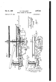
- Fig. l' is a sectional view taken substantially on line l-I of Fig. 3 corresponding to line l-l of Fig. 6 and shows a portion or" the record changing mechanism of the present invention Ain non-operating 'condition during the record playing cycle of the phonograph operation
- Fig. 2 shows essentially the ⁇ same View of the same parts shownin Fig. 1 in operating position for effecting the record changingy cycle
- Fig. 3 shows a view looking upward intoy the record changing mechanism mountedon the bottom of the base plate of the record changerV shown in Fig. 6 in one position thereof during the record changing cycle
- Fig. 4 is a view taken substantially on line -l of Fig.
- Fig. 4A Ashows ay sectional view taken substantially on lineAA-IIA of Fig. l;
- Fig. 5 shows a fragmentary view' ofthe same mechanism shown in Fig. 4 but in a position during the record changing cycle;
- Fig. 6 shows a top view of the base plate of the record changer with turntable, tone arm, and record supporting and selecting discs. In these gures the same members are indicated by the same reference numerals.
- a base plate IB upon which the record changer mechanism is mounted.
- a turntable I I driven by a motor I2 mounted on a mounting plate I3 carried by the base plate I0.
- a friction Wheel I5 rotatably mounted on the mounting plate I3, rotary motion of the motor being transferred to the turntable through the friction wheel I5.
- a rotatable spindle I1 adapted to be driven by the turntable I'I through the friction coupling provided by the slightly resilient member 18 bearing on the turntable II in conventional manner.
- 'Ihe spindle dI1 is guided by means of a guide sleeve I9 secured at one end to the mounting plate I3.
- the record changing mechanism includes a pair of rotatable record supporting and selecting discs 20 and 2I, shown in Fig. 6, located in elevated positions with respect to the turntable II and attached for rotatable movement to shafts 22 and 23, respectively, carrying knurled knobs 24 and 25 for manual operation at their ends above the base plate IIJ.
- These discs and particular features thereof are described and claimed in co-pending application S. N. 589,791, now abandoned, by the present applicant entitled Record FeedingMechanism, led on the same date as the present application and assigned to the same assignee.
- Each of these discs possesses a lower segmentary section 26, an inclined segmentary section 21, a higher segmental-y section' 23, and a tongue member 23.
- any other type of rotatable record selecting device adapted to select a record from a stack when rotated in one direction is deemed a fu-ll equivalent of the discs shown and described herein, merely by way of example and that the record selecting device may take other forms and shapes.
- a. sprocket wheel 33 and 3l respectively, is fixedly attached.
- a sprocket cam wheel S3 For vertical and horizontal movement of a tone arm 32 there is provided a sprocket cam wheel S3.
- an endless chain 34 which also engages with a pair of idlers 35 and 36, adjustably mounted for rotatable movement on the mounting plate I3, and which also engages with a driving sprocket wheel 31.
- the driving sprocket wheel 31 is a portion of a separate rotatable driving member 38, surrounding and guided by the xedly mounted guide sleeve I9 and held in position for rotatable movement with respect thereto as shown.
- the driving member 38 normally stationary during the record playing cycle is provided with a lever portion 39.
- the lower end of the spindle I1 carries in a radial bore a pin 42 which is fixedly attached to the spindle and adapted to become engaged with extension 4
- a small coil spring 43 With one of its ends secured on an extension of the clutch lever 4G and its other end pressing against the bottom end of the spindle I1, as shown. In this. position the pin 42 rotates freely and does not engage with extension 4I of the clutch lever 4U during reproduction of the record.
- a clutch actuating lever 44 which is pivotally supported by .a supporting bracket 45 mounted on the bottom of base plate I0 as shown.
- the lever 44 is provided with an extension 44B which is adapted to come into engagement under pressure of the coil spring 43, with an opening 46 (Fig. 4A in the sprocket cam Wheel 33, which opening is of elongated rectangular shape with its short side extending radially on the sprocket cam wheel 33 as shown in Fig. 4A.
- the tone arm 32 is pivotally hinged to a rotatably mounted shaft 41, to the other end of which an L-shaped member 48 is of a second L-shaped member 49 the cam and ratchet lever 50 is attached to the member 48, so that a rigid connection exists between the tone arm 32 and the ratchet lever 50.
- This lever 50 which is also shown in Figs. 3 and 6, is provided at its free end with a ratchet portion 5I comprising a series of saw-tooth shaped embossments or indentations as is conventional.
- a pivotally mounted pawl 52 adapted to cooperate with the ratchet portion 5I of lever 50, pawl 52 being pivotally hinged to a trigger member 53 which in turn is pivotally hinged to a supporting bracket 54, which is xedly attached to the bottom side of the base plate I0.
- a release lever 55 guided in two guide openings in the supporting bracket 54 as shown in Fig. 4 and held under tension by a relatively weak coil spring 56 attached between one end of release lever 55 and the bottom of the base plate I0 and by a second relatively strong coil spring 51 attached between the other end of release lever 55 and a post 58 eccentrically mounted on the sprocket cam wheel 33.
- this lever is provided with an edge 55B, which is held under pressure by the coil spring 51 against an adjacent abutment on the supporting bracket 54 in Fig. 4.
- This abutment onr bracket 54 acts as a stop member for the release lever 55.
- the pawl and ratchet arrangement 5l, 52 is a so called tripping or releasing device for the record changing mechanism and depends for its operation on the direction of motion of the tone arm, as is well known in the art
- the lever 56 is provided also with an extension carrying a screw 58, the end of which is engageable with an extension 53B of the trigger member 53 for raising lever 55 over the abutment on bracket 54 to provide a tripping mechanism which depends solely on the position of the tone arm, as is likewise well known in the art.
- the record changing mechanism can be released either by a change in the direction of motion of the tone arm due to an eccentric tripping groove on therecord or by arrival of the tone arm at a predetermined position on the record. It is understood, however, that the particular type of releasing device used is immaterial to the present invention.
- the cam and ratchet lever is provided with a cam portion A, best visible in Fig. 3, which is engageable with a post 59 eccentrically mounted on sprocket wheel 33.
- a longitudinally movable rod t! (Fig. l) which normally rests, due to gravity forces acting thereon, in a depression 5I of the cam and sprocket wheel 33 out of Contact with the tone arm during the record playing cycle and rides on the upper surface thereof during the record changing cycle, thereby to raise the tone arm above the plane of the record.
- Fig. 1 of the drawings which shows the record changing mechanism in non-operating condition
- the motor l2 drives the turntable il by way of motor shaft I4 and friction wheel l5.
- the record I6 on the turntable and the spindle l1 with its pin 42 rotate in the direction indicated whereby the tone arm 32 follows the playing groove of the record by coaction therewith of its stylus or needle.
- the pin 42 (Fig. l) rotates freely since the extension 4I of clutch lever 40 is held out of its path by means of the compression spring 43.
- the clutch actuating lever 44 is in the position shown with its end 44B engaged in the opening 43 of the wheel 33 for arresting the record changing mechanism.
- are in the positions shown in Figs. l and 6.
- Pawl 52 hangs freely from ther trigger member 53 while the ratchet lever 50 is remote therefrom in the position indicatedin Figs. l and 4 and gradually approaches the pawl as the tone arm nears the center of the record.
- the post 53 on sprocket wheel 30 is in its extremeV position so that the spring 51 hold the release member 55 in the position indicated in Fig. 4 under maximum tension with its edge 55B pressing the adjacent abutment 54A on the supporting bracket 54.
- the tone arm raising rod 5i] rests by gravity forces acting thereon in the depression 6l of wheel 33, and the post 59 is out-of engagement with the cam portion 50A of lever 5B.
- the release of release lever 55 in Fig; 4 may also be effected by means of the screwv 58 which when near the extremeend of its travel causes rotation of the trigger member 53 in -clo'ckwise direction to release the release lever 55.
- the ensuing operation is the same as described above.
- the tone arm 32 is raised by means of rod 60 when wheel 33 is rotated and it is moved outwardly by means of the post 59 coacting with the cam portion 50A of lever 50.
- Discs 20 and 2l are rotated in the direction indicated whereby their tongue portions 29 are inserted into the stack of records in such manner that the bottommost record is segregated therefrom and, after continued rotation of the discs, released to drop by its own weight upon the turntable or, upon a played record or records already thereon.
- the automatic record changer is loaded with a stack of records which are normally supported by the supporting sections 26 of the record supporting discs 20 and 2l of Fig. 6 wherein the record changing mechanism is disengaged.
- one of the knobs 24 or 25 is rotated counterclockwise through a relatively small angle sufcient to free the record changing mechanism and to establish the driving connection between the latter and the motor in the same manner as described above for the case of rejecting a record.
- the discs 20 and 2i execute a complete revolution during which the tongue members 29 of the discs segregate the bottommost record from the stack and release the same to fall by its own weight upon the turntable whereupon the i-lrst record playing cycle begins.
- a mechanical trip mechanism for a record changer including a single-revolution element rotatable about an axis, a driving element, and a cam-operated clutch for completing a driving connection between said elements, comprising: a release member' movable in a direction substantially normal to said axis from a first position to a second position, including a cam surface for operatingv said clutch during movement thereof, and including a stop recess; a lock member having a stop abutment engaging said recess normally to lock said release member in said rst position; a rst spring connected between said release member and an eccentrically disposed portion of said single-revolution element and biasing said release member for movement toward said second position; means for releasing said recess from said stop abutment to permit movement of said release member to said second position; and a second spring, having a modulus of elasticity less than that of said first spring, connected to said release member and biasing said member to said first position, thereby to restore said member to said rst position
- a mechanical trip mechanism for a record changer including a single-revolution element rotatable about an axis, a driving element, and a cam-operated clutch for completing a driving connection between said elements, comprising: a guide member positioned adjacent said singlerevolution element and including an opening extending in a direction substantially normal to said axis; a release member supported in said opening of said guide member for movement in the direction of said opening from a rst position to a second position, including a cam surface for operating said clutch during movement thereof, and including a stop recess; a, lock member having a stop abutment engaging said recess normally to lock said release member in said first position; a first spring connected between said release member and an eccentrically disposed portion of said single-revolution element and biasing said release member for movement toward said second position; means for releasing said recess from said stop abutment to permit movement of said release member to said second position; and a second spring, having a modulus of elasticity less than that of said first spring,
- a mechanical trip mechanism for a record changer including a single-revolution element rotatable about an axis, a driving element, and a cam-operated clutch for completing a driving connection between said elements, comprising: a guide member positioned adjacent said singlerevolution element and including an opening extending in a direction substantially normal to said axis; a release member supported in said opening of said guide member for movement in the direction of said opening from a first position to a second position, including a cam surface for operating said clutch during movement thereof, and including a stop recess; a lock member having a stop abutment, supported on said guide member, engaging said recess normally to lock said release member in said first position; a first spring connected between said release member and an eccentrically disposed portion of said single-revolution element and biasing said release member for movement toward said second position; means for releasing said recess from said stop abutment to permit movement of said release member to said second position; and a second spring, having a modulus of elasticity less than that of said
- a mechanical trip mechanism for a record changer including a single-revolution element rotatable about an axis, a driving element, and a cam-operated clutch for completing a driving ber for movement toward said second position;
- a mechanical trip mechanism for a record changer including a single-revolution element rotatable about an axis, a driving element, and a cam-operated clutch for completing a driving connection between said elements, comprising: a release member movable in a direction substantially normal to said axis from a rst position to a second position, including a cam surface for operating said clutch during movement thereof, and including a stop recess; a lock member having a stop abutment engaging said recess normally to lock said release member in said first position; a pin eccentrically positioned on said single-revolution element; a first spring connected between said release member and said pin and biasing said release member for movement toward said second position; means for releasing said recess from said stop abutment to permit movement of said release member to said second position; and a second spring, having a modulus of elasticity less than that of said first spring, connected to said release member and biasing said member to said first position, thereby to restore said member to said iirst
Landscapes
- Holding Or Fastening Of Disk On Rotational Shaft (AREA)
Description
Oct.l 3l, 1950 R. A. MULLANEY 2,527,646
RECORD CHANGER TRIP MEcHANIsM INVENTOR.
Oct. 31, 1950 R. A; MULLANEY RECORD CHANGER TRIP MECHANISM 4 Sheets-Sheet -2 Filed April 25, 1945 BEL, l5@ Fa. A. MULLANEY RECORD CHANGER TRIP MECHANISM Fil-ed pxil 23, 1945 INVENTOR.
11% g 5 wy /Qrro/fy @do 35E? i195@ R. A. MULLANEY RECORD CHANGER TRIP mEcHANsM 4 Sheets-Sheet Filed April 23, 1945 INVENTOR. WO/MLZa/w' BY @y ,QTEY
Patented Oct. 31, 1950 RECORD CHANGER TRIP MECHANISM Ralph A. Mullaney, 'Elmwood Park, Ill., assignor to Zenith Radio Corporation, a corporation of Illinois Application April 23, 1945, Serial No. 589,792
Claims. (Cl. 274-1) This invention relates to automatic phonographs and more particularly relates to an improved automatic record changer for phonographs.
In most conventional automatic phonographs, a single motor is provided for driving the turntable upon which rests the disc record to be reproduced and for driving the record-changing mechanism, which includes mechanism for se lecting one of a stack of records and placing the selected record upon the turntable, as well as mechanism for swinging the tone arm out of the path of the selectedrecord during its movement towards the turntable and for placing the tone arm into playing position for playing the selected record. In such phonographs, there is provided a clutch for coupling the record-changing mechanism with the motor during the record changing cycle of the phonograph operation. This clutch is usually actuated for engagement of the motor with the record changing mechanism by means of the tone arm, whereby the actuation may be initiated dependent upon the position of the tone arm, the speed of motion of the tone arm, or the direction of motion of the tone arm, as is well known in the art.
In the usual operation of an automatic phonograph, the phonograph isloaded with a stack of records, while no record is on the turntable. For the purpose of initiating the operation of the phonograph there is provided a button which,
whenoperated, initiates arecord changing cycleA by actuating the clutch for engaging `the motor with the record changing mechanism. A record is then selected* from the stack and placed on the turntable, andthetone arm is swung into playing position.
During the operation or the phonograph it sometimes is not desired to reproduce fully a selected record whichis being played, and therefore conventional phonographs are provided with a reject button. When this button is operated, a
record changing cycle is initiated independentlyv Wol fore in poorly illuminated and inconvenient spots in most conventional phonographs. Since' phonographs are mostly operated by persons'unfamiliar with themechanics thereof, it is desirable to reduce the number of necessary controlsto a minimum and to place the essential controls" in readily accessible and clearly visible locations.
The object of the present invention, therefore, is to provide a new and improved record changing mechanism in which the number of essential controls is reduced to a minimum and wherein these controls may be placed in accessible and clearly visible locations.
Another object of the present invention is to ,l provide a record changing mechanism which is of simpler construction than those hitherto' known, while performing all'the necessary functions of known mechanisms.
In accordance with the present invention there is provided in an automatic record changer including a rotatable turntable and a motor, the combination of a mechanism adapted to be driven by the motor for successively transferring successive ones of a plurality of records into playing position on the turntable during successive record; changing cycles, and means actuated by movement of the mechanism for establishing a driving connection between the motor and themechanism therebyto initiate one of the record changing cycles. j
A For a better understanding of the invention;4 together with other and further objects thereof, reference is had to the following.` description taken in connection with the accompanying drawings, and its scope will be pointed out in the appended claims.
In the accompanying drawings, Fig. l'is a sectional view taken substantially on line l-I of Fig. 3 corresponding to line l-l of Fig. 6 and shows a portion or" the record changing mechanism of the present invention Ain non-operating 'condition during the record playing cycle of the phonograph operation, while Fig. 2 shows essentially the `same View of the same parts shownin Fig. 1 in operating position for effecting the record changingy cycle. Fig. 3 shows a view looking upward intoy the record changing mechanism mountedon the bottom of the base plate of the record changerV shown in Fig. 6 in one position thereof during the record changing cycle; Fig. 4 is a view taken substantially on line -l of Fig. 1, corresponding to line 1 -,Ii of Fig. 3, showing certain partsof the clutch actuating mechanism; Fig. 4A Ashows ay sectional view taken substantially on lineAA-IIA of Fig. l; Fig. 5 shows a fragmentary view' ofthe same mechanism shown in Fig. 4 but in a position during the record changing cycle; and Fig. 6 shows a top view of the base plate of the record changer with turntable, tone arm, and record supporting and selecting discs. In these gures the same members are indicated by the same reference numerals.
Referring now more particularly to Figs. 1 and 3 of the drawings, there is shown a base plate IB upon which the record changer mechanism is mounted. For playing records there is provided a turntable I I driven by a motor I2 mounted on a mounting plate I3 carried by the base plate I0. Between the motor shaft I4 and the rim of the turntable I I there is provided a friction Wheel I5 rotatably mounted on the mounting plate I3, rotary motion of the motor being transferred to the turntable through the friction wheel I5.
For centering record I6 on the turntable there is provided a rotatable spindle I1 adapted to be driven by the turntable I'I through the friction coupling provided by the slightly resilient member 18 bearing on the turntable II in conventional manner. 'Ihe spindle dI1 is guided by means of a guide sleeve I9 secured at one end to the mounting plate I3.
The record changing mechanism includes a pair of rotatable record supporting and selecting discs 20 and 2I, shown in Fig. 6, located in elevated positions with respect to the turntable II and attached for rotatable movement to shafts 22 and 23, respectively, carrying knurled knobs 24 and 25 for manual operation at their ends above the base plate IIJ. These discs and particular features thereof are described and claimed in co-pending application S. N. 589,791, now abandoned, by the present applicant entitled Record FeedingMechanism, led on the same date as the present application and assigned to the same assignee. Each of these discs possesses a lower segmentary section 26, an inclined segmentary section 21, a higher segmental-y section' 23, and a tongue member 23. It is understood, however, that any other type of rotatable record selecting device adapted to select a record from a stack when rotated in one direction is deemed a fu-ll equivalent of the discs shown and described herein, merely by way of example and that the record selecting device may take other forms and shapes.
Referring to Fig. 3 shown the bottom ends of rotatable disc shafts 22 and 23 to each of which a. sprocket wheel 33 and 3l, respectively, is fixedly attached. For vertical and horizontal movement of a tone arm 32 there is provided a sprocket cam wheel S3. For rotating the sprocket wheels 3D, 3l, and 33 in synchronism there is provided an endless chain 34 which also engages with a pair of idlers 35 and 36, adjustably mounted for rotatable movement on the mounting plate I3, and which also engages with a driving sprocket wheel 31.
Referring to Fig. l, in which the connected sprocket wheels 3D and 3| are not shown for the sake of simplicity, it is seen that the driving sprocket wheel 31 is a portion of a separate rotatable driving member 38, surrounding and guided by the xedly mounted guide sleeve I9 and held in position for rotatable movement with respect thereto as shown. The driving member 38 normally stationary during the record playing cycle is provided with a lever portion 39.
For the purpose of driving endless chain 34 and thus `providing a driving connection between the record changing mechanism including sprocket of the drawings there are xedly attached. By means Wheels 30, 3| and 33, and chain driving sprocket wheel 31, and the motor I2, and more specifically, to provide a driving connection between the spindile I1 and the sprocket wheel portion 31 of driving member 38 there is provided a clutch comprising a clutch lever 4U pivotally attached to driving member 38, and having an extension 4I. The lower end of the spindle I1 carries in a radial bore a pin 42 which is fixedly attached to the spindle and adapted to become engaged with extension 4| of the clutch lever 4I] when the same is pivoted upwards, thereby to establish a driving connection between the spindle I1 and the driving sprocket wheel 31. In order to maintain the clutch in disengagement during the record playing cycle of the phonograph there is provided a small coil spring 43 with one of its ends secured on an extension of the clutch lever 4G and its other end pressing against the bottom end of the spindle I1, as shown. In this. position the pin 42 rotates freely and does not engage with extension 4I of the clutch lever 4U during reproduction of the record.
For bringing the extension 4I of the clutch lever 46 into engagement with the pin 42 against the 4pressure of the coil spring 43 there is provided a clutch actuating lever 44 which is pivotally supported by .a supporting bracket 45 mounted on the bottom of base plate I0 as shown. For arresting the motion of the record changing mechanism at the end of a record changing cycle and during the record playing cycle the lever 44 is provided with an extension 44B which is adapted to come into engagement under pressure of the coil spring 43, with an opening 46 (Fig. 4A in the sprocket cam Wheel 33, which opening is of elongated rectangular shape with its short side extending radially on the sprocket cam wheel 33 as shown in Fig. 4A.
For actuating the clutch at the end of each record playing cycle and thereby to initiate a record changing cycle the tone arm 32 is pivotally hinged to a rotatably mounted shaft 41, to the other end of which an L-shaped member 48 is of a second L-shaped member 49 the cam and ratchet lever 50 is attached to the member 48, so that a rigid connection exists between the tone arm 32 and the ratchet lever 50. This lever 50, which is also shown in Figs. 3 and 6, is provided at its free end with a ratchet portion 5I comprising a series of saw-tooth shaped embossments or indentations as is conventional.
Referring now to Fig. 4 of the drawings, showing a cross section through Fig. 1 taken substantially along the line 4 4, there is shown a pivotally mounted pawl 52 adapted to cooperate with the ratchet portion 5I of lever 50, pawl 52 being pivotally hinged to a trigger member 53 which in turn is pivotally hinged to a supporting bracket 54, which is xedly attached to the bottom side of the base plate I0. For releasing the record changing mechanism and actuating the clutch by means of the clutch actuating lever 44 or, more specifically, for disengaging the extension 44B of lever 44 from a locking engagement with the opening 46 in sprocket wheel 33 and for bringing the clutch projection 4I into engagement with pin 42 against the pressure of the coil spring 43 of Fig. l, there is provided a release lever 55 guided in two guide openings in the supporting bracket 54 as shown in Fig. 4 and held under tension by a relatively weak coil spring 56 attached between one end of release lever 55 and the bottom of the base plate I0 and by a second relatively strong coil spring 51 attached between the other end of release lever 55 and a post 58 eccentrically mounted on the sprocket cam wheel 33. For maintaining the release lever 55 in the non-operating position during the record playing cycle this lever is provided with an edge 55B, which is held under pressure by the coil spring 51 against an adjacent abutment on the supporting bracket 54 in Fig. 4. This abutment onr bracket 54 acts as a stop member for the release lever 55. In the vrecord changing oper-ating condition the release lever 55 assumes the position indicated in Fig. and engages with and raises one end of the lever 44 at the cam surface 55C to the position indicated by dotted lines in Fig. 4. Upward movement of lever 44 to the dotted position causes engagement of pin 42 with extension 4i and starts the record changing cycle.
While the pawl and ratchet arrangement 5l, 52 is a so called tripping or releasing device for the record changing mechanism and depends for its operation on the direction of motion of the tone arm, as is well known in the art, the lever 56 is provided also with an extension carrying a screw 58, the end of which is engageable with an extension 53B of the trigger member 53 for raising lever 55 over the abutment on bracket 54 to provide a tripping mechanism which depends solely on the position of the tone arm, as is likewise well known in the art. Hence the record changing mechanism can be released either by a change in the direction of motion of the tone arm due to an eccentric tripping groove on therecord or by arrival of the tone arm at a predetermined position on the record. It is understood, however, that the particular type of releasing device used is immaterial to the present invention.
In the foregoing the features of the invention have been described permitting release of the record changing mechanism according to direction of movement or position of the tone arm. Since it is also desired to initiate a record changing cycle independently of the tone arm movement or position the end 44B of the actuating lever 44, which is engageable with the opening 46 in sprocket cam wheel 33, is provided with a slanting edge 44C as shown in Fig. 4A. The amount by which the edge 44C slants is so chosen that a movement of wheel 33 in the direction of the arrow produces a `downward motion of the lever end 44B until it finally becomes totally disengaged from its locking engagement with the opening and rests against thev lower surface of the wheel disc 33 whereby the record changing mechanism is released and the clutch actuated by the other end of the actuating lever 44.
For controlling the horizontal motion of the tone arm 32 during the record changing cycle the cam and ratchet lever is provided with a cam portion A, best visible in Fig. 3, which is engageable with a post 59 eccentrically mounted on sprocket wheel 33. For vertical motion of the tone arm 32 the latter is coupled to a longitudinally movable rod t!! (Fig. l) which normally rests, due to gravity forces acting thereon, in a depression 5I of the cam and sprocket wheel 33 out of Contact with the tone arm during the record playing cycle and rides on the upper surface thereof during the record changing cycle, thereby to raise the tone arm above the plane of the record. Additional features can be incorporated to enable the phonograph automatically to play intermixed records having diameters of l0 and l2 inches respectively. Reference is made to my copending applicatiomserial Number 589,781, nowthe pawl 52 idles over the same.
abandoned, filed concurrently herewith in which The operation of the apparatus described is now explained. Referring first to Fig. 1 of the drawings, which shows the record changing mechanism in non-operating condition, the motor l2 drives the turntable il by way of motor shaft I4 and friction wheel l5. The record I6 on the turntable and the spindle l1 with its pin 42 rotate in the direction indicated whereby the tone arm 32 follows the playing groove of the record by coaction therewith of its stylus or needle. The pin 42 (Fig. l) rotates freely since the extension 4I of clutch lever 40 is held out of its path by means of the compression spring 43. The clutch actuating lever 44 is in the position shown with its end 44B engaged in the opening 43 of the wheel 33 for arresting the record changing mechanism. The record supporting and selecting discs 2Q and 2| are in the positions shown in Figs. l and 6. Pawl 52 hangs freely from ther trigger member 53 while the ratchet lever 50 is remote therefrom in the position indicatedin Figs. l and 4 and gradually approaches the pawl as the tone arm nears the center of the record.
The post 53 on sprocket wheel 30 is in its extremeV position so that the spring 51 hold the release member 55 in the position indicated in Fig. 4 under maximum tension with its edge 55B pressing the adjacent abutment 54A on the supporting bracket 54.
The tone arm raising rod 5i] rests by gravity forces acting thereon in the depression 6l of wheel 33, and the post 59 is out-of engagement with the cam portion 50A of lever 5B.
As the tone arm 32 approaches the center of the record and is close to entering the tripping groove thereon the Vfree end of lever 50 with the ratchet portion 5| and the pawl 52 assume the positions indicated in Fig. 5. While the ratchet portion travels from right to left in Figs. 4 and 5 However, when the tone arm stylus travels in the eccentric tripping groove on the record, lever 50 suffers a revers-al of direction of its movement and' the ratchet portion 5l moves from left to right thereby positively engaging the pawl 52 and rotating the trigger member 53 counterclockwise about its pivot point in Figs. 4 and 5. Such rotation of member 53 causes raising of the release lever 55, freeing its edge 55B from the supporting bracket 54. and the force of the spring 51 pulls the release lever 55 from right to left and upwards. Lever 55 then engages the actuating lever 44 at the cam surface 55C and raises the latter, thereby disengaging its end 44B from the opening 46 in the wheel 33 shown in Fig. l, to free the record changing mechanism and at the same time to raise the` other end 44A of actuating lever 44 against the pressure of spring 53 of Fig. 1 to move extension 4l into the path of rotating pin 42 whereby a driving connection is established between the motor i2 and driving sprocket wheel 31 which drivessprocket wheels 3o, 3l and 33 by means of the chain 34 as shown in Fig. 3. record changing mechanism in operating condition during a changing cycle is shown in Fig. 2.
The release of release lever 55 in Fig; 4 may also be effected by means of the screwv 58 which when near the extremeend of its travel causes rotation of the trigger member 53 in -clo'ckwise direction to release the release lever 55. The ensuing operation is the same as described above.
Referring now to Figs. 2 and 3, the tone arm 32 is raised by means of rod 60 when wheel 33 is rotated and it is moved outwardly by means of the post 59 coacting with the cam portion 50A of lever 50. Discs 20 and 2l are rotated in the direction indicated whereby their tongue portions 29 are inserted into the stack of records in such manner that the bottommost record is segregated therefrom and, after continued rotation of the discs, released to drop by its own weight upon the turntable or, upon a played record or records already thereon. The remainder of the record stack is supported by portions 28 of the discs and then lowered by the inclined portions 21 until they are again supported by portions 26 after a complete revolution of the discs as eX- plained more fully in my above mentioned application, Serial Number 589,791, iiled concurrently herewith.
Meanwhile the end 44B of the clutch actuating lever 44 rides on the lower surface of wheel 33, thereby maintaining the clutch in engagement during the record changing cycle. In Fig. 3 the sprocket wheels 39, 3| and 33 are driven to rotate clockwise (since the bottom of base plate lll is now viewed) and the post 58 eccentrically mounted on the wheel 30 moves inwardly thereby releasing the tension on the spring 5l until the tension of the spring 56, which is normally weaker than that of spring 5T, becomes predominant and pulls the release lever 55 from left to right as shown in Fig. 4 and into its original position where its edge portion 55B again engages with the adjacent abutment 54A of the supporting bracket 54. During further rotation of wheel 39 the post 58 moves outwardly again until it reassumes its extreme position at the end of a complete revolution wherein the coil spring 5l is under maximum tension.
After a complete revolution of the wheel 33 the end 44B of clutch actuating lever 44 drops into engagement with the opening 46 of wheel 33 due to the force exerted on the lever by the compressed coil spring 43. The clutch member 4U drops and its extension 4| moves out of engagement with the pin 42, thus interrupting the driving connection between the motor l2 and the record changing mechanism. This terminates the record changing cycle during which the record supporting and selecting discs 20 and 2l and the sprocket wheels 35, 3| and 33 each have completed one full revolution. At the end of cycle the tone arm 32 is brought into proper playing position by coaction of pin 59 with the cam surface 59A and a new record playing cycle begins.
While in the foregoing description the record changing cycle was initiated by the tone arm, the operation of the apparatus is now described for initiating a record changing cycle regardless of the position or movement of the tone arm. If it is desired to reject a record which is being played or to place the rst record on the turntable, one of the knurled knobs 24 or 25 of Fig. 6 is rotated counterclockwise. Such a rotation of knobs 25 or 26 is possible in spite of the fact that end 44B of clutch actuating lever 44 eX- tends through the opening 46 of wheel 33. This is so because it is evident from Figure 4A that rotation of wheel 33 produced by rotating knobs 22 or 23 manually causes the lever end 44B to be cammed downwardly until it rides on the lower surface of wheel 33. The downward movement of the lever end 44B simultaneously causes the other end of clutch actuating lever 44 to move upwardly and thereby to cause engagement between clutch elements 4I and 42 to initiate a record changing cycle in the manner described above.
Starting of an automatic phonograph employing the described mechanism is also eiected in the same manner as just described. The automatic record changer is loaded with a stack of records which are normally supported by the supporting sections 26 of the record supporting discs 20 and 2l of Fig. 6 wherein the record changing mechanism is disengaged. In order to start operation, one of the knobs 24 or 25 is rotated counterclockwise through a relatively small angle sufcient to free the record changing mechanism and to establish the driving connection between the latter and the motor in the same manner as described above for the case of rejecting a record. The discs 20 and 2i execute a complete revolution during which the tongue members 29 of the discs segregate the bottommost record from the stack and release the same to fall by its own weight upon the turntable whereupon the i-lrst record playing cycle begins.
From the foregoing description it will be apparent that there has been provided a new and improved record changing mechanism of extremely simple and eincient construction which requires no separate mechanism for starting its operation or rejecting records, but in which a small movement of the record changing mechanism itself suiiices to bring about a driving connection between the latter and its driving motor.
While the present embodiment shows a single motor for driving both the record turntable and the record changing mechanism, it is understood that a separate motor can equally well be provided for the changing mechanism, in which case the clutch is arranged between the mechanism and the separate motor, as will be readily seen by those skilled in the art.
While there has been described what is at present considered the preferred embodiment of the invention, it will be obvious to those skilled in the art that various changes and modifications may be made therein without departing from the invention, and it is, therefore, aimed in the appended claims to cover all such changes and modifications as fall within the true spirit and scope of the invention.
What is claimed is:
1. A mechanical trip mechanism for a record changer including a single-revolution element rotatable about an axis, a driving element, and a cam-operated clutch for completing a driving connection between said elements, comprising: a release member' movable in a direction substantially normal to said axis from a first position to a second position, including a cam surface for operatingv said clutch during movement thereof, and including a stop recess; a lock member having a stop abutment engaging said recess normally to lock said release member in said rst position; a rst spring connected between said release member and an eccentrically disposed portion of said single-revolution element and biasing said release member for movement toward said second position; means for releasing said recess from said stop abutment to permit movement of said release member to said second position; and a second spring, having a modulus of elasticity less than that of said first spring, connected to said release member and biasing said member to said first position, thereby to restore said member to said rst position after a predetermined rotation of said single-revolution member.
2. A mechanical trip mechanism for a record changer including a single-revolution element rotatable about an axis, a driving element, and a cam-operated clutch for completing a driving connection between said elements, comprising: a guide member positioned adjacent said singlerevolution element and including an opening extending in a direction substantially normal to said axis; a release member supported in said opening of said guide member for movement in the direction of said opening from a rst position to a second position, including a cam surface for operating said clutch during movement thereof, and including a stop recess; a, lock member having a stop abutment engaging said recess normally to lock said release member in said first position; a first spring connected between said release member and an eccentrically disposed portion of said single-revolution element and biasing said release member for movement toward said second position; means for releasing said recess from said stop abutment to permit movement of said release member to said second position; and a second spring, having a modulus of elasticity less than that of said first spring, connected to said release member and biasing said member to said first position, thereby to restore said member to said rst position after a predetermined rotation of said singlerevolution member.
3. A mechanical trip mechanism for a record changer including a single-revolution element rotatable about an axis, a driving element, and a cam-operated clutch for completing a driving connection between said elements, comprising: a guide member positioned adjacent said singlerevolution element and including an opening extending in a direction substantially normal to said axis; a release member supported in said opening of said guide member for movement in the direction of said opening from a first position to a second position, including a cam surface for operating said clutch during movement thereof, and including a stop recess; a lock member having a stop abutment, supported on said guide member, engaging said recess normally to lock said release member in said first position; a first spring connected between said release member and an eccentrically disposed portion of said single-revolution element and biasing said release member for movement toward said second position; means for releasing said recess from said stop abutment to permit movement of said release member to said second position; and a second spring, having a modulus of elasticity less than that of said first spring, connected to said release member and biasing said member to said first position, thereby to restore said member to said rst position after a predetermined rotation of said single-revolution member.
4. A mechanical trip mechanism for a record changer including a single-revolution element rotatable about an axis, a driving element, and a cam-operated clutch for completing a driving ber for movement toward said second position;
means for releasing said recess from said stop abutment to permit movement of said release member to said second position; and a second spring, having a modulus of elasticity less than that of said first spring, connected to the other end of said release member and biasing said member to said first position, thereby to restore said member to said rst position after a predetermined rotation of said single-revolution member.
5. A mechanical trip mechanism for a record changer including a single-revolution element rotatable about an axis, a driving element, and a cam-operated clutch for completing a driving connection between said elements, comprising: a release member movable in a direction substantially normal to said axis from a rst position to a second position, including a cam surface for operating said clutch during movement thereof, and including a stop recess; a lock member having a stop abutment engaging said recess normally to lock said release member in said first position; a pin eccentrically positioned on said single-revolution element; a first spring connected between said release member and said pin and biasing said release member for movement toward said second position; means for releasing said recess from said stop abutment to permit movement of said release member to said second position; and a second spring, having a modulus of elasticity less than that of said first spring, connected to said release member and biasing said member to said first position, thereby to restore said member to said iirst position after a predetermined rotation of said single-revolution member.
RALPH A. MULLANEY.
REFERENCES CITED The following references are of record in the le of this patent:
UNITED STATES PATENTS Number Name Date 1,841,593 Benjamin Jan. 19, 1932 1,931,487 Collison et al. Oct. 24, 1933 2,031,449 Arvidius Feb. 18, 1936 2,287,560 Osborne et al June 23, 1942 2,313,193 Delchef Mar. 9, 1943 2,339,981 Cranmer et al Jan. 25, 1944 FOREIGN PATENTS Number Country Date 394,326 Great Britain June 14, 1933
Priority Applications (1)
| Application Number | Priority Date | Filing Date | Title |
|---|---|---|---|
| US589792A US2527646A (en) | 1945-04-23 | 1945-04-23 | Record changer trip mechanism |
Applications Claiming Priority (1)
| Application Number | Priority Date | Filing Date | Title |
|---|---|---|---|
| US589792A US2527646A (en) | 1945-04-23 | 1945-04-23 | Record changer trip mechanism |
Publications (1)
| Publication Number | Publication Date |
|---|---|
| US2527646A true US2527646A (en) | 1950-10-31 |
Family
ID=24359534
Family Applications (1)
| Application Number | Title | Priority Date | Filing Date |
|---|---|---|---|
| US589792A Expired - Lifetime US2527646A (en) | 1945-04-23 | 1945-04-23 | Record changer trip mechanism |
Country Status (1)
| Country | Link |
|---|---|
| US (1) | US2527646A (en) |
Cited By (3)
| Publication number | Priority date | Publication date | Assignee | Title |
|---|---|---|---|---|
| US2670210A (en) * | 1945-04-18 | 1954-02-23 | Philco Corp | Phonograph apparatus |
| US2795429A (en) * | 1950-05-11 | 1957-06-11 | Admiral Corp | Automatic record player |
| US2898111A (en) * | 1949-06-15 | 1959-08-04 | Admiral Corp | Phonograph record player trip mechanism |
Citations (7)
| Publication number | Priority date | Publication date | Assignee | Title |
|---|---|---|---|---|
| US1841593A (en) * | 1921-08-25 | 1932-01-19 | James H Benjamin | Self-operating talking machine |
| GB394326A (en) * | 1931-12-14 | 1933-06-14 | Frank Allen Mitchell | Improvements in and relating to automatic record-transferring devices for gramophones and like apparatus |
| US1931487A (en) * | 1931-06-27 | 1933-10-24 | Capehart Corp | Automatic phonograph |
| US2031449A (en) * | 1934-08-28 | 1936-02-18 | Arvidius Svante Philip | Automatic gramophone |
| US2287560A (en) * | 1940-04-11 | 1942-06-23 | Wurlitzer Co | Automatic phonograph |
| US2313193A (en) * | 1939-03-23 | 1943-03-09 | Delchef Georges | Automatic phonograph |
| US2339981A (en) * | 1941-08-21 | 1944-01-25 | Philco Radio & Television Corp | Automatic phonograph |
-
1945
- 1945-04-23 US US589792A patent/US2527646A/en not_active Expired - Lifetime
Patent Citations (7)
| Publication number | Priority date | Publication date | Assignee | Title |
|---|---|---|---|---|
| US1841593A (en) * | 1921-08-25 | 1932-01-19 | James H Benjamin | Self-operating talking machine |
| US1931487A (en) * | 1931-06-27 | 1933-10-24 | Capehart Corp | Automatic phonograph |
| GB394326A (en) * | 1931-12-14 | 1933-06-14 | Frank Allen Mitchell | Improvements in and relating to automatic record-transferring devices for gramophones and like apparatus |
| US2031449A (en) * | 1934-08-28 | 1936-02-18 | Arvidius Svante Philip | Automatic gramophone |
| US2313193A (en) * | 1939-03-23 | 1943-03-09 | Delchef Georges | Automatic phonograph |
| US2287560A (en) * | 1940-04-11 | 1942-06-23 | Wurlitzer Co | Automatic phonograph |
| US2339981A (en) * | 1941-08-21 | 1944-01-25 | Philco Radio & Television Corp | Automatic phonograph |
Cited By (3)
| Publication number | Priority date | Publication date | Assignee | Title |
|---|---|---|---|---|
| US2670210A (en) * | 1945-04-18 | 1954-02-23 | Philco Corp | Phonograph apparatus |
| US2898111A (en) * | 1949-06-15 | 1959-08-04 | Admiral Corp | Phonograph record player trip mechanism |
| US2795429A (en) * | 1950-05-11 | 1957-06-11 | Admiral Corp | Automatic record player |
Similar Documents
| Publication | Publication Date | Title |
|---|---|---|
| US2287098A (en) | Automatic record changing apparatus | |
| US2376741A (en) | Pickup arm control | |
| US2371362A (en) | Record changing mechanism for phonographs | |
| US2818263A (en) | Phonograph | |
| US4063286A (en) | Video disc player | |
| US2586422A (en) | Tone arm indexing apparatus | |
| US2527646A (en) | Record changer trip mechanism | |
| US1377027A (en) | Phonograph | |
| US2357520A (en) | Automatic record changing mechanism | |
| US2298988A (en) | Tripping mechanism for automatic record changers | |
| US2230106A (en) | Phonographic record changer | |
| US2707639A (en) | Phonograph record player control | |
| US2284305A (en) | Record changing mechanism for phonographs | |
| US3633923A (en) | Handy acoustic reproducing device | |
| US2287727A (en) | Automatic phonograph | |
| US2684248A (en) | Record player with an automatic record changer | |
| US2622885A (en) | Record changing apparatus | |
| US3578335A (en) | Sound track changeover device for automatic playing apparatus having a plurality of endless tape cartridges | |
| US3073604A (en) | Automatic phonograph | |
| US2918288A (en) | Record changers for phonographs | |
| US3507503A (en) | Record player | |
| US2529474A (en) | Automatic phonograph | |
| US3417998A (en) | Vertical record player | |
| US1855563A (en) | Talking machine | |
| US2732212A (en) | carson |