US25140A - Jambs h - Google Patents
Jambs h Download PDFInfo
- Publication number
- US25140A US25140A US25140DA US25140A US 25140 A US25140 A US 25140A US 25140D A US25140D A US 25140DA US 25140 A US25140 A US 25140A
- Authority
- US
- United States
- Prior art keywords
- lever
- shears
- arm
- limb
- pin
- Prior art date
- Legal status (The legal status is an assumption and is not a legal conclusion. Google has not performed a legal analysis and makes no representation as to the accuracy of the status listed.)
- Expired - Lifetime
Links
- 210000003414 Extremities Anatomy 0.000 description 22
- 210000001364 Upper Extremity Anatomy 0.000 description 20
- 238000005520 cutting process Methods 0.000 description 14
- 210000003141 Lower Extremity Anatomy 0.000 description 6
- 210000003813 Thumb Anatomy 0.000 description 6
- VKYKSIONXSXAKP-UHFFFAOYSA-N Hexamethylenetetramine Chemical group C1N(C2)CN3CN1CN2C3 VKYKSIONXSXAKP-UHFFFAOYSA-N 0.000 description 2
- 101700065560 andI Proteins 0.000 description 2
- 238000010276 construction Methods 0.000 description 2
- 230000000875 corresponding Effects 0.000 description 2
- 230000000881 depressing Effects 0.000 description 2
- 230000003467 diminishing Effects 0.000 description 2
- 230000000694 effects Effects 0.000 description 2
- 230000000630 rising Effects 0.000 description 2
Images

Classifications
-
- A—HUMAN NECESSITIES
- A01—AGRICULTURE; FORESTRY; ANIMAL HUSBANDRY; HUNTING; TRAPPING; FISHING
- A01G—HORTICULTURE; CULTIVATION OF VEGETABLES, FLOWERS, RICE, FRUIT, VINES, HOPS OR SEAWEED; FORESTRY; WATERING
- A01G3/00—Cutting implements specially adapted for horticultural purposes; Delimbing standing trees
- A01G3/02—Secateurs; Flower or fruit shears
- A01G3/025—Secateurs; Flower or fruit shears having elongated or extended handles
Definitions
- My invention consists in a certain mode- 0f combining one limb 0f a pair ofshears 01' other band outting instrumentwith a handle forming part of a separate lever and combiningthe said limb and handle With the other limb of*the shears whereby the leverage exerted by the thumb or band in cutting is gradually increased as the shears cl0se anda drawing cut is produced.
- A is the blade, and B, the handle,which combine to form the l'ower limb "0f the shears, made in one piece and of such form that the handle as Well as the blade may rest upon the eutting board 0r table during the cutting Operation.
- this limb is made much deeper than is common in other shears, in order that the pin a, on Which the upper blade works may be arranged some distance above the edge of the lower blade.
- the arm D contains a slot d, to receive a pin e, Which is carriedby anarm f, which is attached-to the lever.of which the upper handle 0f the shears forme. a part, and whose 'duty Will be hereinafter explained.
- E is the upper handle constitutin'g a portion of a 'lever E G, and attached t0 the lower limb of the shears by a fulcrum pin g, which is situatedmuch nearer t0 the front end than tothe rear end which terminates in the thumb bow.
- Thearm f which hasloeen beforementioned, is attached to the front extremity 0f thelever E G, and standsnp nearly at a right angle t0 the portion 0f the said handle that is in front 0f the fulcrum pin g, and the said arm is made 0f forked form, as shown in Fig. 4, to receive the arm D, of the upper limb.
- the fork 0f the said arm f also contains a roller 7c, which turns on a pin l, inserted through the said arm; and above the said roller is the before mentioned pin e, working in the slot in the arm D, of the upper limb.
- the roller k works against the bottom of the arm D, of the upper limb, for the purpose 0f forcing up the said arm D, and bringing down the blade C to effect the cutting operation by the depression of the handle E; and the pin e, is for the purpose 0f drawing down the arm D, 130 open the shears as the handle E, is raised.
- T0 provide 'f0r the grinding away 0f the blades by repeated sharpenings of the shears and insure the proper closing 0f the shears and their cutting t0 the points i when ground away, the arm f, is made detached from the lever E G, and 1s secured thereto by a screw m, passing through a s1ot n, in the said arm and screwing into the said lever E.
- the s1ot n permits the adjustment of the said arm f, higher or lower and 130 keep the said arm steady and prevent its being forced out of p1ace by the force applied to it in cutting, there is a steady pin p project-ing from the lever E G, into the said s1ot n, and there are aseries of teeth and notches g g, provided in the said arm, as shown in Figs. 1 and 4, and in the face of the 1ever to Which it is attached.
- H is a spring secured to the lower li1nb A B, of the shears, and pressing against an anti-friction roller r, attached to the 1ever E G, for the purpose of raising and throw ing forvvard the rear or lower end of the said lever am]. so opening or assisting in opening the shears when the said lever is relieved fro1n the pressure of the thumb or band.
- the roller 70 in gradually receding from the pin a, or fulcrum of the upper 1imb C D, is also causing the power applied by the said lever to act w'ith increased eifect 011 the blade, and thus the power exerted by the hand is increased as the cutting takes place farther from the pin er fulcrum a, and diminishes a greater resistance 110 the' closing of the blades.
- This operation is illustrated in Fig. l, by the representation 01 the shears in a closed oondition, in red outline. The operation of the shears is also greatly assisted by the drawing cut that is caused by the elevated position of the pin a.
- the sa1ne eonstruction may be adapted, With some advantage, to hand punches, the punch being attached to the lever O D.
- VVhat I clai1n as my invention, and desire to secure by Letters Patent, is:
Description
'NITED STATES PATENT OFFICE.
JAMES H. ROOME, OE NE"YORK N, Y.
SI-IEARS.
.Specification of Letters Patent 1\To. 25,140, dated August 16, 1859.
T0 all whom- *Lt may concem:
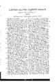
Be itknown that I, JAMES H.R00ME, of the ciy, county, and State of New York, have invented a new and useful Improvement in Tailors and other Shears, which may also be applied to other cutting instruments; andI do'hereby=deelare that the following is a full, clear, and exact descriptionof the Same, re'ference being had to the accoinpanying drawings, formin'g part of this specification, in which- Figures 1 and 2 are opposite-side views 0f a pair of shears constructed aecording to my invent-ion. Fig. 3 is a top view f the same. Fig. 4 is a transverse section-of the samein the same line m, 00, ofFig. 1.
Similar letters ofreference indieate corresponding parts in the several figures.
My invention consists in a certain mode- 0f combining one limb 0f a pair ofshears 01' other band outting instrumentwith a handle forming part of a separate lever and combiningthe said limb and handle With the other limb of*the shears whereby the leverage exerted by the thumb or band in cutting is gradually increased as the shears cl0se anda drawing cut is produced.
T0 enable others skilled in the art to make and use my invention I will proceed to describe its construct-ion and operation.
A is the blade, and B, the handle,which combine to form the l'ower limb "0f the shears, made in one piece and of such form that the handle as Well as the blade may rest upon the eutting board 0r table during the cutting Operation. At the junetion 0f the blade and handle this limb is made much deeper than is common in other shears, in order that the pin a, on Which the upper blade works may be arranged some distance above the edge of the lower blade.
C, D, is the upper limb made in the f0rm 0f a lever of which the upper blade C, constitutes one arm, and the other arm D, is extended rearward from the said blade and from the point where this limb is attached to the lower limb by the pin a. This upper limb is made deep eno ugh below the point' where it receives the p1n a, t0 reach nearly 130 the bottom of the 1imb A B, as shown in Fig. 1, and below the pin a, it contains a slot b, having the form 0f an arc described from the pin a, said slot receiving a broad headed screw c, which screws into the 10Wer limb, and the part 0f the upper limb surrounding the said slot being rather thicker at that end of the said slot nearest the blade than at the other=end thereof, so that in the closingof the shears the faces of the blades Will be drawn tovvard-each einher er gradually pressed tighter against eaeh other. The arm D, contains a slot d, to receive a pin e, Which is carriedby anarm f, which is attached-to the lever.of which the upper handle 0f the shears forme. a part, and whose 'duty Will be hereinafter explained.
E, is the upper handle constitutin'g a portion of a 'lever E G, and attached t0 the lower limb of the shears by a fulcrum pin g, which is situatedmuch nearer t0 the front end than tothe rear end which terminates in the thumb bow. A sl0t h, is-provided in the said leverE- G,for the fulerum pin g, to pass through t0 permit the said handle a longitudinal, as well as a lever=like movement, and the saidpin g, is fitted with an antifriction rollerwithi-n the said slot. The front end of the said lever is connected with the upper limb C D, by a link F, and two joint pins 2', j, the pin j, Which attaches the said link to the said limb being arranged a little in rear 0f and some distance below thepin a, and the pin i, which attaehes the said link to the leverE G, being so= arranged that when the shears are closed the said link Will be parallel er nearly so with the edges of theblades. Thearm f,which hasloeen beforementioned, is attached to the front extremity 0f thelever E G, and standsnp nearly at a right angle t0 the portion 0f the said handle that is in front 0f the fulcrum pin g, and the said arm is made 0f forked form, as shown in Fig. 4, to receive the arm D, of the upper limb. The fork 0f the said arm f, also contains a roller 7c, which turns on a pin l, inserted through the said arm; and above the said roller is the before mentioned pin e, working in the slot in the arm D, of the upper limb. The roller k, works against the bottom of the arm D, of the upper limb, for the purpose 0f forcing up the said arm D, and bringing down the blade C to effect the cutting operation by the depression of the handle E; and the pin e, is for the purpose 0f drawing down the arm D, 130 open the shears as the handle E, is raised. T0 provide 'f0r the grinding away 0f the blades by repeated sharpenings of the shears and insure the proper closing 0f the shears and their cutting t0 the points i when ground away, the arm f, is made detached from the lever E G, and 1s secured thereto by a screw m, passing through a s1ot n, in the said arm and screwing into the said lever E. The s1ot n, permits the adjustment of the said arm f, higher or lower and 130 keep the said arm steady and prevent its being forced out of p1ace by the force applied to it in cutting, there is a steady pin p project-ing from the lever E G, into the said s1ot n, and there are aseries of teeth and notches g g, provided in the said arm, as shown in Figs. 1 and 4, and in the face of the 1ever to Which it is attached.
H, is a spring secured to the lower li1nb A B, of the shears, and pressing against an anti-friction roller r, attached to the 1ever E G, for the purpose of raising and throw ing forvvard the rear or lower end of the said lever am]. so opening or assisting in opening the shears when the said lever is relieved fro1n the pressure of the thumb or band.
In operating With these shears the lower limb is allowed to rest on the outting hoard er table; and the cut is produced by depressing the upper handle, and, at the sa1ne time, pulling or pressing it. in a backward direction from the position shown in Fig. 2, and in blaok outline in Fig. l. This 1novement of the handle oauses the front end of the lever E G, w'hich is connected with the upper limb to rise, and the arm f, 130 1nove backward, and so cause the roller 7c, to pass along the lower edge of the arm D, of the upper limb, and so depress the upper blade C; but, atthe same time, the end of the 1ink F Which is attached to the rising front end the lever E G, is raised by the said lever and the said link is forced bodily ba'ckward by the movernent of the limb C D, and so oaused to force back the said lever bodily on its fulorurn g, thus gradually increasing the length of the said lever behind the said pin and diminishing its length in front thereof,
and so increasing its ower as the b1ade C, descends and While this increase of power of the said 1ever is taking place, the roller 70, in gradually receding from the pin a, or fulcrum of the upper 1imb C D, is also causing the power applied by the said lever to act w'ith increased eifect 011 the blade, and thus the power exerted by the hand is increased as the cutting takes place farther from the pin er fulcrum a, and diminishes a greater resistance 110 the' closing of the blades. This operation is illustrated in Fig. l, by the representation 01 the shears in a closed oondition, in red outline. The operation of the shears is also greatly assisted by the drawing cut that is caused by the elevated position of the pin a.
The sa1ne eonstruction may be adapted, With some advantage, to hand punches, the punch being attached to the lever O D.
VVhat I clai1n as my invention, and desire to secure by Letters Patent, is:
Combining one limb C D, of a pair of shears, or other similarly operating band eutting instrument, With its handle E, forming part of a separate lever E G, and combining the said lirnb and handle with the other 1irnb of t-he shears, by means of an arm f, attached to the said lever E G, and operating 011 the rear portion D, of the first mentioned limb, a link F, connecting the said li1nb with the said lever, and a movable fulorum connection g, h, between the said lever and the other 1imb; the who1e operating substantially as described -to cause the power of ehe said lever to inorease as the shears elose.
JAMES H. ROOME.
Witnesses:
J. W. COOMBS, R. S. SPENCER.
Publications (1)
| Publication Number | Publication Date |
|---|---|
| US25140A true US25140A (en) | 1859-08-16 |
Family
ID=2093782
Family Applications (1)
| Application Number | Title | Priority Date | Filing Date |
|---|---|---|---|
| US25140D Expired - Lifetime US25140A (en) | Jambs h |
Country Status (1)
| Country | Link |
|---|---|
| US (1) | US25140A (en) |
Cited By (5)
| Publication number | Priority date | Publication date | Assignee | Title |
|---|---|---|---|---|
| US2689401A (en) * | 1953-09-14 | 1954-09-21 | Lewis Engineering And Mfg Comp | Grass shears having a pivoted blade and offset handle |
| US5618258A (en) * | 1995-03-25 | 1997-04-08 | Olympus Winter & Ibe Gmbh | Thumb ring for an endoscopic apparatus |
| US20110126415A1 (en) * | 2009-11-29 | 2011-06-02 | Ho Cheng Garden Tools Co., Ltd. | Garden shears |
| US20110214293A1 (en) * | 2010-03-02 | 2011-09-08 | Yao-Chung Huang | Gardening Shears Having Energy-Saving Function |
| US9358693B1 (en) * | 2015-03-20 | 2016-06-07 | Eric T. Berger | Shears |
-
0
- US US25140D patent/US25140A/en not_active Expired - Lifetime
Cited By (7)
| Publication number | Priority date | Publication date | Assignee | Title |
|---|---|---|---|---|
| US2689401A (en) * | 1953-09-14 | 1954-09-21 | Lewis Engineering And Mfg Comp | Grass shears having a pivoted blade and offset handle |
| US5618258A (en) * | 1995-03-25 | 1997-04-08 | Olympus Winter & Ibe Gmbh | Thumb ring for an endoscopic apparatus |
| US20110126415A1 (en) * | 2009-11-29 | 2011-06-02 | Ho Cheng Garden Tools Co., Ltd. | Garden shears |
| US8166659B2 (en) * | 2009-11-29 | 2012-05-01 | Ho Cheng Garden Tools Co., Ltd. | Garden shears |
| US20110214293A1 (en) * | 2010-03-02 | 2011-09-08 | Yao-Chung Huang | Gardening Shears Having Energy-Saving Function |
| US8225513B2 (en) * | 2010-03-02 | 2012-07-24 | Ho Cheng Garden Tools Co., Ltd. | Gardening shears having energy-saving function |
| US9358693B1 (en) * | 2015-03-20 | 2016-06-07 | Eric T. Berger | Shears |
Similar Documents
| Publication | Publication Date | Title |
|---|---|---|
| US2434550A (en) | Combination implement | |
| US25140A (en) | Jambs h | |
| US1458878A (en) | Scissors or pruners for cutting fruit, flowers, or the like | |
| US2766526A (en) | Metal shears | |
| US2569888A (en) | Pruning implement | |
| US1969129A (en) | Cutting implement | |
| US21369A (en) | roome | |
| US2679096A (en) | Grass shears having push means for actuating a blade thereof | |
| US1368244A (en) | Plaster-of-paris cutter | |
| US1436010A (en) | Finger-nail trimmer | |
| US34368A (en) | Improved device for cutting the noses of swine to prevent them from rooting | |
| US20879A (en) | Tailor s shears | |
| US35116A (en) | Improvement in stationary counter-scissors | |
| US573110A (en) | Stock-marker | |
| US718796A (en) | Hoof-trimmer. | |
| US26955A (en) | Joseph smith | |
| US1137380A (en) | Pruning-shears. | |
| US513542A (en) | Shears | |
| US2528326A (en) | Shears | |
| US1552688A (en) | Combination tack puller and scissors | |
| US40010A (en) | Improvement in shears and scissors | |
| US328249A (en) | Harry wilson parkee | |
| US481897A (en) | Sprout-puller | |
| US2714762A (en) | Multi-blade hedge trimmer | |
| US1472633A (en) | Hedge trimmer |