US2513627A - Flow indicator for milking machines - Google Patents
Flow indicator for milking machines Download PDFInfo
- Publication number
- US2513627A US2513627A US791904A US79190447A US2513627A US 2513627 A US2513627 A US 2513627A US 791904 A US791904 A US 791904A US 79190447 A US79190447 A US 79190447A US 2513627 A US2513627 A US 2513627A
- Authority
- US
- United States
- Prior art keywords
- chamber
- milk
- flow indicator
- head
- milking machines
- Prior art date
- Legal status (The legal status is an assumption and is not a legal conclusion. Google has not performed a legal analysis and makes no representation as to the accuracy of the status listed.)
- Expired - Lifetime
Links
Images
Classifications
-
- G—PHYSICS
- G01—MEASURING; TESTING
- G01P—MEASURING LINEAR OR ANGULAR SPEED, ACCELERATION, DECELERATION, OR SHOCK; INDICATING PRESENCE, ABSENCE, OR DIRECTION, OF MOVEMENT
- G01P13/00—Indicating or recording presence, absence, or direction, of movement
- G01P13/008—Indicating or recording presence, absence, or direction, of movement by using a window mounted in the fluid carrying tube
-
- A—HUMAN NECESSITIES
- A01—AGRICULTURE; FORESTRY; ANIMAL HUSBANDRY; HUNTING; TRAPPING; FISHING
- A01J—MANUFACTURE OF DAIRY PRODUCTS
- A01J5/00—Milking machines or devices
- A01J5/04—Milking machines or devices with pneumatic manipulation of teats
- A01J5/041—Milk claw
Definitions
- My invention relates broadly to milking machinery-and more specifically to a novel milk flow indicating device therefor.
- An important-object of my invention is'the*provision of a milk flow indicating device which is inexpensive to manufacture, foolproof in operation, which is highly sanitary in -use and is extremely easy to disassemble and-clean.
- Another important object of my invention is the provision of a novel combination of milk pail cover and milk flow indicator, which is interposed in the lines leading from the teat cups to the pail.
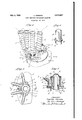
- Fig. 1 is a, fragmentary perspective view showing my novel milk flow indicator applied to the removable cover of a milk pail;
- Fig. 2 is a transverse section taken substantially on the line 22 of Fig. 1;
- Fig. 3 is a vertical section taken substantially on the line 3-3 of Fig. 2;
- Fig. 4 is a view in perspective of the bafile element used in my device.
- the numeral I indicates a milk pail, preferably of the type to be suspended by a strap or the like underneath the belly of the cow in close proximity to the teats.
- the pail I is provided with a removable cover 2 which is seated thereon, a resilient sealing washer 3 being preferably interposed therebetween.
- a conventional pulsator 4 Rigidly secured to the cover 2 is a conventional pulsator 4.
- a coupling head or claw 5 which is provided with a plurality of radially extending circumferentially spaced nipples 6, to which the milk tubes 1 leading from a plurality of teat cups 8 are adapted to be fastened.
- teat cups 8 are also provided with air tubes 9, which lead to the pulsator 4 and thence to a suction pump (not shown) through the suction hose I0.
- a chamber I I having a cylindrical side wall H and an annular bottom wall I2.
- nipples 6 have passages I3 therein which terminate in circumferentially spaced relationship in the side wall II of the chamber II above the bottom thereof.
- the annular bottom. wall I2 provides an opening I4 which is'notched as indicated at I5, forpurp'ose which will hereinafter become apparent.
- a tubular element It of a diameter'slightly less than that of the opening I4 is provided intermediate its upper and lower ends with a radially project ing circumferentially extending flange ll, which is adapted to rest upon the annular bottom wall I2 of the chamber II.
- a radially projecting axially extended key I8 on the tubular element I6, immediately below the flange IT, is adapted to be contained within the notch I5 to prevent rotation of the tubular element I6.
- the portion of the tubular element It which projects above the flange I'I forms an annular baffle I9 which is radially inwardly spaced from the side wall of the chamber II, and is concentric therewith.
- a segmental slot 20 extends from the top of the baffie I 9 downwardly to the flange I1 and provides an opening from the chamber I I to the interior of the milk pail. It will be observed, particularly by reference to Figs. 2 and 3, that the opening or slot 20 in the bafile I9 is circumferentially spaced from the inlet passages I3. Thus the baffle I9 and the wall II of the chamber II define a segmental deflecting channel 2
- a transparent top 22 Overlying the baffle I9 and closing the upper end of chamber II is a transparent top 22, preferably dome-like in shape, which is spaced from the upper end of bafile I9 and is secured to the head 5 by means of an annular screw-threaded clamping element 23.
- a sealing washer 24 be-' tween the top 22 and the clamping element 23 provides an air-tight seal at the upper end of the chamber II.
- the milk flow indicator may be quickly cleaned by simply unscrewing the clamping ring 23 and lifting the tubular element Hi from the chamber H.
- a milk flow indicator adapted to be inserted into the milk lines leading from a plurality of teat cups, said indicator comprising a coupling head, said head being provided with a verticallyextended bore which terminates short of the bottom wall of said head, said bore and said bottom wall providing a cylindrical chamber, said bottom wall being provided with a reduced concentric discharge opening, a plurality of circumferen-' tially-spaced nipples projecting radially of the outside of said head and each communicating with said chamber, a tubular bafi'le having a radially-projecting circumferentially-extended flange adjacent its base adapted to rest upon the bottom wall of said head within said chamber, said baffle being concentric with the side wall of said chamber and being spaced inwardly therefrom to provide a milk-deflecting chamber, said bafile being provided with an axially-extended slot which extends from the upper end thereof to said flange, means preventing rotation of said baflle with respect to said head, and a removable transparent top in
- the means for preventing rotation of said baffle within said chamber comprises a radially-projected key which extends from said flange to the base of said baffle, the bottom wall of said coupling head being provided with a notch adapted to receive said key.
Description
July 4, 1950 L. DINESEN mow INDICATOR FOR MILKING MACHINES Fil ed Dec 15, 1947 Patented Jul 4, 1950 UNITED STATES PATENT OFFICE FLOW INDICATORFOR MILKIN G MACHINES Laurits Dinesen, Minneapolis, Minn, ass'ignorto Perfection ManufacturingCorporation, Minneapolis, Minn, a corporation of Minnesota Application December 15, 1947, Serial No. 791,904
2-Claims. 1
My invention relates broadly to milking machinery-and more specifically to a novel milk flow indicating device therefor.
' An important-object of my invention is'the*provision of a milk flow indicating device which is inexpensive to manufacture, foolproof in operation, which is highly sanitary in -use and is extremely easy to disassemble and-clean.
Another important object of my invention is the provision of a novel combination of milk pail cover and milk flow indicator, which is interposed in the lines leading from the teat cups to the pail.
The above and still further objects and advantages of my invention will become apparent from the following detailed specification, appended claims, and attached drawings.
Referring to the drawings, in which like characters indicate like parts throughout the several views:
Fig. 1 is a, fragmentary perspective view showing my novel milk flow indicator applied to the removable cover of a milk pail;
Fig. 2 is a transverse section taken substantially on the line 22 of Fig. 1;
Fig. 3 is a vertical section taken substantially on the line 3-3 of Fig. 2; and
Fig. 4 is a view in perspective of the bafile element used in my device.
Referring with greater particularity to the drawings, the numeral I indicates a milk pail, preferably of the type to be suspended by a strap or the like underneath the belly of the cow in close proximity to the teats. The pail I is provided with a removable cover 2 which is seated thereon, a resilient sealing washer 3 being preferably interposed therebetween. Rigidly secured to the cover 2 is a conventional pulsator 4. Also secured to the cover 2, preferably in spaced relation to the pulsator 4, is a coupling head or claw 5, which is provided with a plurality of radially extending circumferentially spaced nipples 6, to which the milk tubes 1 leading from a plurality of teat cups 8 are adapted to be fastened. As shown, teat cups 8 are also provided with air tubes 9, which lead to the pulsator 4 and thence to a suction pump (not shown) through the suction hose I0.
Within the head 5 is a chamber I I having a cylindrical side wall H and an annular bottom wall I2.
It will be noted that the nipples 6 have passages I3 therein which terminate in circumferentially spaced relationship in the side wall II of the chamber II above the bottom thereof. 56
The annular bottom. wall I2 provides an opening I4 which is'notched as indicated at I5, forpurp'ose which will hereinafter become apparent. A tubular element It of a diameter'slightly less than that of the opening I4 is provided intermediate its upper and lower ends with a radially project ing circumferentially extending flange ll, which is adapted to rest upon the annular bottom wall I2 of the chamber II. A radially projecting axially extended key I8 on the tubular element I6, immediately below the flange IT, is adapted to be contained within the notch I5 to prevent rotation of the tubular element I6. The portion of the tubular element It which projects above the flange I'I, forms an annular baffle I9 which is radially inwardly spaced from the side wall of the chamber II, and is concentric therewith.
A segmental slot 20 extends from the top of the baffie I 9 downwardly to the flange I1 and provides an opening from the chamber I I to the interior of the milk pail. It will be observed, particularly by reference to Figs. 2 and 3, that the opening or slot 20 in the bafile I9 is circumferentially spaced from the inlet passages I3. Thus the baffle I9 and the wall II of the chamber II define a segmental deflecting channel 2|.
Overlying the baffle I9 and closing the upper end of chamber II is a transparent top 22, preferably dome-like in shape, which is spaced from the upper end of bafile I9 and is secured to the head 5 by means of an annular screw-threaded clamping element 23. A sealing washer 24 be-' tween the top 22 and the clamping element 23 provides an air-tight seal at the upper end of the chamber II.
From the above it should be obvious that milk from the teat cups 8, entering the chamber II through the inlet passages I3 of the nipples B, will be impinged upon the sides of the deflecting baffle I9 with suflicient force to cause at least a portion of the milk to be deflected upwardly against the transparent dome-like top 22, thus making it possible for the operator to detect the flow at all times. It will be noted that the bulk of the milk entering the chamber II will flow around the baffle I9 and through the slot 20 into the milk pail I. Furthermore, in view of the fact that the slot 2% extends completely to the base of the flange I9, all milk within the chamber II will be drained ofi into the pail I, under the action of gravity, when the machine is stopped. This is an important factor for sanitation.
When, however, it becomes necessary to wash or rinse the milking apparatus, the milk flow indicator may be quickly cleaned by simply unscrewing the clamping ring 23 and lifting the tubular element Hi from the chamber H.
My novel device has been commercially tried and found to be completely satisfactory for the accomplishment of the above objects, and while I have disclosed a commercial form of my invention, it should be obvious that the same is capable of modification without departure from the scope and spirit of the appended claims.
What I claim is:
1. A milk flow indicator adapted to be inserted into the milk lines leading from a plurality of teat cups, said indicator comprising a coupling head, said head being provided with a verticallyextended bore which terminates short of the bottom wall of said head, said bore and said bottom wall providing a cylindrical chamber, said bottom wall being provided with a reduced concentric discharge opening, a plurality of circumferen-' tially-spaced nipples projecting radially of the outside of said head and each communicating with said chamber, a tubular bafi'le having a radially-projecting circumferentially-extended flange adjacent its base adapted to rest upon the bottom wall of said head within said chamber, said baffle being concentric with the side wall of said chamber and being spaced inwardly therefrom to provide a milk-deflecting chamber, said bafile being provided with an axially-extended slot which extends from the upper end thereof to said flange, means preventing rotation of said baflle with respect to said head, and a removable transparent top in the upper portion of said head positioned over and in spaced relation to the deflecting bafile.
2. "The structure defined in claim 1 in which the means for preventing rotation of said baffle within said chamber comprises a radially-projected key which extends from said flange to the base of said baffle, the bottom wall of said coupling head being provided with a notch adapted to receive said key.
" LAURITS DINESEN.
REFERENCES CITED The following references are of record in the file of this patent:
UNITED STATES PATENTS 2,376,717 Omdalen May 22, 1945
Priority Applications (1)
| Application Number | Priority Date | Filing Date | Title |
|---|---|---|---|
| US791904A US2513627A (en) | 1947-12-15 | 1947-12-15 | Flow indicator for milking machines |
Applications Claiming Priority (1)
| Application Number | Priority Date | Filing Date | Title |
|---|---|---|---|
| US791904A US2513627A (en) | 1947-12-15 | 1947-12-15 | Flow indicator for milking machines |
Publications (1)
| Publication Number | Publication Date |
|---|---|
| US2513627A true US2513627A (en) | 1950-07-04 |
Family
ID=25155156
Family Applications (1)
| Application Number | Title | Priority Date | Filing Date |
|---|---|---|---|
| US791904A Expired - Lifetime US2513627A (en) | 1947-12-15 | 1947-12-15 | Flow indicator for milking machines |
Country Status (1)
| Country | Link |
|---|---|
| US (1) | US2513627A (en) |
Cited By (14)
| Publication number | Priority date | Publication date | Assignee | Title |
|---|---|---|---|---|
| US2613637A (en) * | 1949-11-18 | 1952-10-14 | Babson Bros Co | Lid for suspended milkers |
| US3232273A (en) * | 1964-01-10 | 1966-02-01 | Dairy Equipment Co | Flow indicating lid construction for bucket milking apparatus |
| US3496905A (en) * | 1965-01-23 | 1970-02-24 | Plastic Products Ltd | Milk flow indicator |
| US4873943A (en) * | 1987-12-28 | 1989-10-17 | Dairy Equipment Co. | Milk flow indicator |
| EP0531928A2 (en) * | 1991-09-11 | 1993-03-17 | ITT Automotive Europe GmbH | Device for collecting liquids from several sources in a container |
| US6058880A (en) * | 1996-02-05 | 2000-05-09 | Alfa Laval Agri Ab | Claw for a milking machine |
| US6298807B1 (en) * | 1999-04-08 | 2001-10-09 | Delaval, Inc. | Top unloading tapered barrel claw |
| WO2001078499A2 (en) * | 2000-04-13 | 2001-10-25 | Delaval Inc. | Milking claw with concave window |
| US6895892B2 (en) * | 2002-10-01 | 2005-05-24 | Westfaliasurge, Inc. | Short milk tube |
| USD830649S1 (en) | 2016-01-28 | 2018-10-09 | Gea Farm Technologies, Inc. | Vent protecting stiffener for a dairy animal milker unit tube |
| US10785952B2 (en) | 2014-11-07 | 2020-09-29 | Gea Farm Technologies, Inc. | Short milk tube with protective vent for a dairy animal milker unit |
| US11516990B2 (en) | 2019-08-19 | 2022-12-06 | Gea Farm Technologies, Inc. | Milker unit short milk tube with milk claw end connector |
| US11632931B2 (en) | 2019-08-19 | 2023-04-25 | Gea Farm Technologies, Inc. | Milker unit short milk tube with milk claw end connector |
| USD1022350S1 (en) | 2021-09-22 | 2024-04-09 | Gea Farm Technologies, Inc. | Milker unit short milk tube milk claw end connector |
Citations (6)
| Publication number | Priority date | Publication date | Assignee | Title |
|---|---|---|---|---|
| US975127A (en) * | 1909-07-31 | 1910-11-08 | Velie Motor Vehicle Company | Sight-feed. |
| US1367630A (en) * | 1920-03-31 | 1921-02-08 | Bernard H Skelly | Sight-feed for force-feed lubricators |
| US1919172A (en) * | 1927-08-24 | 1933-07-18 | Universal Milking Machine Comp | Milking apparatus |
| US2329396A (en) * | 1938-08-19 | 1943-09-14 | Dinesen Laurits | Individual vacuum regulator for milking machines |
| US2345819A (en) * | 1943-09-13 | 1944-04-04 | Thomas H Kirk | Milking apparatus |
| US2376717A (en) * | 1938-09-02 | 1945-05-22 | Clarence E Omdalen | Milking apparatus |
-
1947
- 1947-12-15 US US791904A patent/US2513627A/en not_active Expired - Lifetime
Patent Citations (6)
| Publication number | Priority date | Publication date | Assignee | Title |
|---|---|---|---|---|
| US975127A (en) * | 1909-07-31 | 1910-11-08 | Velie Motor Vehicle Company | Sight-feed. |
| US1367630A (en) * | 1920-03-31 | 1921-02-08 | Bernard H Skelly | Sight-feed for force-feed lubricators |
| US1919172A (en) * | 1927-08-24 | 1933-07-18 | Universal Milking Machine Comp | Milking apparatus |
| US2329396A (en) * | 1938-08-19 | 1943-09-14 | Dinesen Laurits | Individual vacuum regulator for milking machines |
| US2376717A (en) * | 1938-09-02 | 1945-05-22 | Clarence E Omdalen | Milking apparatus |
| US2345819A (en) * | 1943-09-13 | 1944-04-04 | Thomas H Kirk | Milking apparatus |
Cited By (19)
| Publication number | Priority date | Publication date | Assignee | Title |
|---|---|---|---|---|
| US2613637A (en) * | 1949-11-18 | 1952-10-14 | Babson Bros Co | Lid for suspended milkers |
| US3232273A (en) * | 1964-01-10 | 1966-02-01 | Dairy Equipment Co | Flow indicating lid construction for bucket milking apparatus |
| US3496905A (en) * | 1965-01-23 | 1970-02-24 | Plastic Products Ltd | Milk flow indicator |
| US4873943A (en) * | 1987-12-28 | 1989-10-17 | Dairy Equipment Co. | Milk flow indicator |
| EP0531928A2 (en) * | 1991-09-11 | 1993-03-17 | ITT Automotive Europe GmbH | Device for collecting liquids from several sources in a container |
| WO1993004976A2 (en) * | 1991-09-11 | 1993-03-18 | Alfred Teves Gmbh | Arrangement for collecting liquid from several sources in a collecting recipient |
| WO1993004976A3 (en) * | 1991-09-11 | 1993-05-27 | Teves Gmbh Alfred | Arrangement for collecting liquid from several sources in a collecting recipient |
| EP0531928A3 (en) * | 1991-09-11 | 1993-06-09 | Alfred Teves Gmbh | Device for collecting liquids from several sources in a container |
| US6058880A (en) * | 1996-02-05 | 2000-05-09 | Alfa Laval Agri Ab | Claw for a milking machine |
| US6298807B1 (en) * | 1999-04-08 | 2001-10-09 | Delaval, Inc. | Top unloading tapered barrel claw |
| WO2001078499A2 (en) * | 2000-04-13 | 2001-10-25 | Delaval Inc. | Milking claw with concave window |
| WO2001078499A3 (en) * | 2000-04-13 | 2002-02-21 | Delaval Inc | Milking claw with concave window |
| US6401655B1 (en) * | 2000-04-13 | 2002-06-11 | Delaval Inc. | Milking claw with concave window |
| US6895892B2 (en) * | 2002-10-01 | 2005-05-24 | Westfaliasurge, Inc. | Short milk tube |
| US10785952B2 (en) | 2014-11-07 | 2020-09-29 | Gea Farm Technologies, Inc. | Short milk tube with protective vent for a dairy animal milker unit |
| USD830649S1 (en) | 2016-01-28 | 2018-10-09 | Gea Farm Technologies, Inc. | Vent protecting stiffener for a dairy animal milker unit tube |
| US11516990B2 (en) | 2019-08-19 | 2022-12-06 | Gea Farm Technologies, Inc. | Milker unit short milk tube with milk claw end connector |
| US11632931B2 (en) | 2019-08-19 | 2023-04-25 | Gea Farm Technologies, Inc. | Milker unit short milk tube with milk claw end connector |
| USD1022350S1 (en) | 2021-09-22 | 2024-04-09 | Gea Farm Technologies, Inc. | Milker unit short milk tube milk claw end connector |
Similar Documents
| Publication | Publication Date | Title |
|---|---|---|
| US2513627A (en) | Flow indicator for milking machines | |
| US3150637A (en) | Milking machine milker | |
| US2233852A (en) | Cleaner for dairy equipment | |
| US2547797A (en) | Milk filter | |
| US4516592A (en) | Milker unit washer | |
| US2484696A (en) | Teat cup | |
| US2896573A (en) | Milking machine and teat cup assembly therefor | |
| US1259309A (en) | Milking-machine. | |
| US3172391A (en) | High speed milking system | |
| US4803950A (en) | Automatic milking apparatus | |
| US2556596A (en) | Control device for milking machines | |
| US3012566A (en) | Washing apparatus for milking machine inflations | |
| US4185586A (en) | Milk sensor for machine remover | |
| US2944514A (en) | Teat cup inflation | |
| US1393387A (en) | Milking-machine system | |
| US2630783A (en) | Releaser assembly for continuous milking systems | |
| US2665663A (en) | Suspended milker | |
| US2690734A (en) | Pressure release valve for milk hose of milking machines | |
| US5857424A (en) | Position-adaptor for milking machine inflations | |
| US3029787A (en) | Claw assembly for milking machines | |
| US2603396A (en) | Apparatus for filling milk cans by vacuum, with means for straining and cooling saidmilk | |
| US2853051A (en) | Attachment for milking machine | |
| US3176654A (en) | Milking device | |
| US1786846A (en) | Milking machine | |
| US2581530A (en) | Milking machine trap |