US2513402A - Telefacsimile communication - Google Patents
Telefacsimile communication Download PDFInfo
- Publication number
- US2513402A US2513402A US590369A US59036945A US2513402A US 2513402 A US2513402 A US 2513402A US 590369 A US590369 A US 590369A US 59036945 A US59036945 A US 59036945A US 2513402 A US2513402 A US 2513402A
- Authority
- US
- United States
- Prior art keywords
- frequency
- motor
- generator
- photocell
- output
- Prior art date
- Legal status (The legal status is an assumption and is not a legal conclusion. Google has not performed a legal analysis and makes no representation as to the accuracy of the status listed.)
- Expired - Lifetime
Links
Images

Classifications
-
- H—ELECTRICITY
- H04—ELECTRIC COMMUNICATION TECHNIQUE
- H04N—PICTORIAL COMMUNICATION, e.g. TELEVISION
- H04N1/00—Scanning, transmission or reproduction of documents or the like, e.g. facsimile transmission; Details thereof
- H04N1/44—Secrecy systems
- H04N1/448—Rendering the image unintelligible, e.g. scrambling
Definitions
- This-invention relates ;to systems, and appae ratus for the secret transmission ofpictures,- in-, cludingefacsimiles ,oft'written or typed, messages and maps.
- signals -" may be --distorted' andthe recording of elemental areas maybedisplaced from their actual positions if the'transmission is received on a convention uniform-rate recording device.
- This method produces an unintelligible copy or record on a-conventional receiver, as explained inmy copendingapplication, Ser; No. 414,247, whichissued-as a patent July 23, 1946, No.
- Another. object of theinvention is to; provide an improved arrangement .for the secret. trans.- mission of intelligencetin. which the signal distortion means utilized in. connection. with the,
- Anotherobjectof the invention is to provide, ina picturestnansmissionsystem of the character described, improved means-for distorting or scrambling, the signals at the transmitterand for correcting or "decoding the signals-:with greater precision at the receiver;
- A'iurther objectofttheinvention is to improve the construction. and: characteristics of variablefrequency current generators in general.
- Fig. 2 illustrates a cam controlled optical generator for the transmitter and receiver of Fig. 1.
- Fig. 3 illustrates'another form of variable-frequency generator that may be used in connection with the system shown in Fig. 1.
- Fig. 4 is a fragmentary detail view of one the chopper discs of Fig. 3.
- Figs. 5, 6 and 7 are graphs of thevoutput signals
- the generator shown in Fig. 2 is of the electrooptical type comprising a light source 20, a photoelectric cell 2
- the chopper wheel 22' is mounted on the rotating shaft 24 a'n'd" is adapted to rotate at a constant speed.
- the aperture plate 23 is mounted upon a shaft 25 which is arranged to obtained under certain conditions with the appa- 1 I beam directed'upon the photocell, thus increasing and decreasing the frequency of the impulses ratus of Fig. 3.
- Fig. 8 illustrates a further modification.
- Fig. 9 is a detail view of the optical discused in the system shown in Fig. 8.
- the facsimile system shown by way of example comprises a drum-type transmitter I0, a drum-type receiver H and a connecting wire or radio channel l2 of'any suitable'type. While the invention will be described in connecoscillate first in a clockwise and then in a countor-clockwise direction so that it alternately adds to and subtracts from the frequency of the light The result is the same as if the cell 2
- the transmitter l0 and receiver H are each 3' 2 provided with a motor
- 5A are exactlycontrolled in conventional systems to rotate uni- 3 formly atprecisely the same speed.
- 5A are driven or controlled by variablefrequency impulse generators 11 and HA, which are identical and which have certain special:
- 6 is variedfrom ⁇ time to time so that the scanning rate of thetransmitted copy is varied to produce a relatively rapidand wide-range distortion" of the sig nal output. Since the drum
- consisting of an uninterrupted train of substantially uniform pulses is amplified in an amplifier:2
- , 32 and 33 are provided to control the oscillation of theaperture plate '23.
- , 32 and 33 are driven by any suitable-means, such as worms 34, 35 and 36,'each engaging a'worm Wheel (shown in dotted lines) on the shaft of one of the cams.
- ' pairv preferably has adifferent ratio to avoid a frequent repetition ofthe distortion pattern.
- cams are further provided with cam -followers or rack members 31, 38 and 39, which are geared to the shaft 25 through differential gearing 4
- the motor l5 which is driven by the output of the electro-optical generator, should be a synchronous motor and may. be of the phonic wheel type, similar to thatdisclcsed in my prior patent, Pat. No. 2,276,936, granted March 17, 1942.
- the rotative speed of the rotor of asynchronousmotor of this type will follow the variations in the frequency of the applied current. Therefore if the drum of the receiver is started at the same instant as the drum of the transmitter and the impulse generators are started or.
- FIG. 3 and 4 An electro-optical generator of this type 1 is illustratedin Figs. 3 and" 4.
- two chopper wheels 55 and 36 are shown, but any desired numbermay be used, .as will'be explained.
- Discs A and E5 are-driven by a constant-speed motor 41, for example, at'diiferent rates through the gearing 48.
- Each of the chopper discs 45 and 46 is provided with a plurality ofteeth or apertures of variable spacingv arranged around the periphery of the disc. provided as indicated at'eil and 5
- the distance between adjacent apertures in any particular row is variedso' that as the disc is turned at a uniform speed, the time interval between the impulses generated by the associated photo-electric means will gradually increase and decrease.
- the distance or spacing between the successive apertures in the row 5i varies from dl to (in successively increasing steps or increments. It will be apparent that the rate of change of the spacing between the apertures is related to the rate of change in the speed of the motor driven by the optical generator.
- a master plate may be prepared by precision methods and employed to make any'number of duplicate plates, one of which is used at the transmitting station and'one at each receiving station.
- a separate and distinct aperture spacing plan or; layout is preferably used for each of'the rows of apertures on the different plates 45 and M3, and any other plates that may be employed:
- the chopper disc t5 is interposed between a lightsource 53 and a photocell 54 so that an uninterrupted train of frequency- Two or more rows of apertures may be
- the average frequencies generated by-the' discs: t5 and dt may be 50-and EGG-cycles per; second respectivelygin which case a signaling-current 1 having an average frequency of 150 cycles per second may lee derivednomine -modulator 60;:
- the photocell 5% is connected to the input circuit of an amplifier 5?.
- the photocell 56 associated" with the second chopper disc 36 and light source 55 is connected to the input circuit of an amplifier 58.
- the modulator circuit 63 comprises input-and output transformers B2 and 63respectively, the amplifier 58 being connected to the primary winding of the transformer 6-2; and-the output of-theamplifier 51 being connected to the-centertap of the respective windings of the-transformers BZ-and 63 as-shown.
- modulator S-lf is similar to themodulator 60, but
- the total-outputcurrent-of themodulator is-impressed upen a band-pass fil-terlil which is ad dusted to pass the band-between and cycles.
- The-filtering and shaping circuit is conventional except for a voltage-limiter consisting of two oppositely-poled current limiting elements it, such as selenium rectifiers-Whichhave the property of'high resistance at low valuesof volt-.-
- variable-frequency output current is amplified -by an amplifier Hand used; to energize or control the-driving motor of the:
- Phase shift effect in the modulating system i can be kept to aminimum by limiting thevoltages of- ⁇ both'---fr equencies* to about 0.2 volts If the voltage applied to the rectifier elementsofthe'modulator 60 is high the variable currents from the photoc ells Stand 56 may cancel each other when a -certain phase relation exists between-them-;- In thiscase, the output voltage of the transformer 63 'wil-lvary between'minimum and maXimum -val-uesas indicated by the graph 73in Fig. '5, the minimum value occurring at the point 14: Likewise the-terminal voltage across the transformer 159 will vary at the same time as indicated by the graph in Fig.
- the two modulators 60 and GI are connected in parallel as shown and arranged so that the voltages across both transformers 63 and 69 are added.-- This results in a substantially uniformlevel signaling current of varying frequency as indicated by the curve" in Fig. 7.
- the Variable-frequencyoutput current-from each chopper wheel-photocell unit may be doubled before it is mixed with the current from another unit.
- This arrangement which is illustrated in Fig. 8 has the advantage that therange of frequency variation is doubled and smaller discs may be used.
- two lightmodulating discs 8I and 82 are shown although more could be employed if desired.
- These discs instead of being toothed or perforated discs, are provided with alternately reflecting and nonreflecting segments, as shown in Fig. 9. These rows .of segments may be of the same width or of varying widths. In the latter case, the modulating disc would be rotated at constant speed.
- the segments are all of the same width and'the variation in impulse frequency is obtained bymoving the light source and photocell around the axis of the rotating disc.
- a frame 85, carrying the lamp-photocell unit is mounted in front of each of the discs 8
- the frame 85 is pivoted on the axis of the shaft carrying the modulator disc and is oscillated back and forth by any suitable means such as by a cam 85 and link 81 pivoted at its upper end to a bar 88 carrying the frame 85.
- a cam 85 and link 81 pivoted at its upper end to a bar 88 carrying the frame 85.
- output of the frequency doubler '92 will be anaverage frequency of 100 cycles per second,-varying in accordance with the variations in the original signal train.
- a second frequency doubler- 93 may be provided to obtain an average fre-' quency of 200 cycles per second.
- Each frequency doubler comprises two rectifier elements connected between input and output windings as shownto produce an alternating output voltage of double frequency.
- the rectifiers may be for example of the selenium-type.
- the output terminals of :the filter 9-5 are connected through a transformer 96 and a voltage limiter' circuit to the control-"grid of an amplifier 9B.
- the limiter circuit may consist of two oppositely poled selenium rectifier elements 91, as shown.
- the amplified signals from the amplifier 98, through a transformer '99, are impressed upon a'second filter IN, the output of which is connected to the mixer; I02 where the signals are combined with those generated by the second photo-electric cell generator.
- the signals generated by the;rotation of the disc 82 may be doubled as described above; butas shown, a different method is employed.
- the signals are impressed upon a second tube I08, Which is-arranged to accentuate the third harmonic-of the fundamental frequency.
- the-tube A9? an be a creen g d tub Whitby/operated 8 as a class B amplifier.
- the output current of the amplifier I86 has a large thirdharmonic' of an average frequency of 150 cycles per second.
- the third harmonic is passed throughthe filter I01 designed to pass the 150 cycle band, and through a transformer I68 and voltagelimiter I09, are impressed upon the control-grid of an amplifier I I0.
- the amplified current of an average frequency of 150' cycles per second,...througha transformer III,. is impressed ofthe stabilizer motor. as. connected toythe shaft through coupling springs I24, as more full disclosed in my prior upon fa 's'e cond. filter. I I2.
- Theoutput of the filter II2 isimpressed upon the mixer I02 where it is ;combined with the 200-cycle current passing through the filter IOI.
- the output of the mixer is filtered in the filter H3 and the 350-cycle component is amplified in. an amplifier H4 and utilized to drive a stabilizer unit I I5.
- the sta 'bilizer unit is a motor-generator comprising a driving rotor II6, a flywheel Ill and a generator rotor II8 mounted for rotation on a single shaft. If additional discs similar to the discs 81 and 82 are employed, the output currents of the associated photocells are combined in the same manner as those shown and the current impressed upon the amplifier I I4..
- The. output current from the amplifier I I4 travers'es. a parallel resonant circuit I I9 in series relation withvthe field magnet windings I20 and I2I
- the motor rotor is shown patent, No. 2,27 6,936 above referred to, which discloses the detailed construction of the motor shown as a part of the stabilizer unit.
- the motor circuit is'disclosed'and claimed in my prior patent, No. 2,257,158, dated September 30, 1941.
- the frequency of the current may differ from that impressed upon the-motor, being determined by' the number of poles or teeth on the rotor I I8, and thus the stabilizer unit also serves as a frequency changer.
- the flywheel II'I having considerable inertia
- the pulses from the alternator are nearly of uniform amplitude although their frequency changes in accordance with the variations produced by the electro-optical elements including discs BI and 82 because the driving motor :ltw l lbeapparent that the electro-optical g n. l
- a transmitter provided with a rotatable drum for supporting the copy or picture to be transmitted, a synchronous motor for driving said drum, scanning means associated with said drum, 2.
- variable-frequency generator of the pper ype connected'to said motor to vary the rotative speed of the drum and thereby distort the signal output of the transmitter as compared to a transmitter arranged to scan the copy at a uniform rate, said generator comprising a source of light, a photocell, a light chopper between said source and said photocell and means to vary the rate at which the light chopper interrupts the light on the photocell to cause an uninterrupted train of frequency-modulated impulses to be generated by the photocell, and a receiver provided with means including a second similar variable-frequency generator for correcting for the distortion of the signal output of the transmitter.
- a facsimile transmitter for secret com munication in combination, a rotatable drum for supporting the copy or picture to be transmitted, a synchronous motor for driving said drum, scanning means associated with said drum and electro-optical impulse generating means connected to said motor to operate the same at variable speed, said electro-optical generating means comprising a light chopper and photocell arranged to generate an uninterrupted train of substantially uniform impulses spaced at varying predetermined intervals.
- a facsimile receiver for a system of the character described employing signals generated by scanning the copy at a non-uniform rate, in combination, recording mechanism, a synchronous driving motor therefor and an electro-opti- It will be cal impulse generator connected to operate said motor, said impulsegenerator comprising a rotatable variable-spacing chopper wheel arranged to generate a continuous train of frequency-modulated impulses andthereby drive the motor at a variable rotative speedcorresponding to the nonuniform rate of scanning the copy at the transmitter whereby the, recordingmech'anism.is controlled to correctthe signal distortion.
- a scanning arrangement for a facsimilesystem comprising,. in combination, a rotatable scanning element, asynchronous motor for driving said rotatableelement and an electro-optical impulse generator, connected to said motor, said impulse generator. comprising aphotocell, a light chopper provided with a continuous series of apertures around theQperiphery thereof disposed in front of saidphotocell and means including said photocell and light chop er for generating an uninterrupted" train of frequency-modulated impulses adapted tofdrive the motor continuously with predetermined-fluctuations in speed and thereby vary the speed of the scanningelement.
- a scanning arrangement for a facsimile system comprising, in combination, a rotatable scanning element, a. synchronousmotor forydriving said rotatablescanning element and, a'variablefrequency electro-optical generator connected "to said motor to impart predetermined speed variations to said scanning element, saidgenerator comprising a source of light, a photocell, a rotary chopper wheel interposed betweensaid light and .photocelland a plurality of cams arranged jointly to control the rotative speed of said chopper wheel.
- a scanningarrangement for a facsimile system comprising, in combination, a scanning device, a member adjacent said scanning device for supporting the copy, synchronous motor means for producing relative movement between said scanning device and the copy, and a variablefrequency electro-optical impulse generator connected to said motor means to control the speed of the same, whereby to cause predetermined irregularities in the relative movement between the scanning device and the copy of relatively large magnitude, said impulse generator comprising a photocell, a light source for illuminating the cell and a rotatable chopper wheel disposed in front of said photocell to produce uninterrupted variable-rate impulse excitation of the photocell.
- a scanning arrangement for a facsimile system comprising, in combination, a scanning device, a rotatable drum adjacent said scanning device for supporting the copy, a synchronous motor for driving the drum and a variable-frequency electro-optical impulse generator connected to said motor to control the rotative speed thereof, whereby to cause rotational variations in the movement of the drum of relatively large magnitude, said impulse generator comprising a photocell, a constant-speed chopper-wheel having a series of variably-spaced apertures around the periphery thereof and means including said photocell and chopper wheel to generate an uninterrupted train of variable-frequency current impulses.
- a motor-driven transmitter of the drum type a motor-driven recorder of the drum type, a transmission channel between said transmitter and said recorder, a variable-frequency alternating current generator having a frequencymodulated substantially symmetrical wave out- 11, put connected to the driving motor of the trans: mitter and a second variable-frequency alternating current generator having the same output current characteristics connected to the, driving motor of the recorder, each of said generators comprising impulse-generating means including a light-sensitive device andidentical light choppers operatively associated therewith.
- a motor-driven transmitter of the drum type a motor-driven recorder of'the drum type, a transmission channel between said transmitter and said recorder, a generator having a frequency-modulated substantially symmetrical wave output connected to the driving motor of the transmitter and a second substantially symmetrical wave generator having the same output current characteristics asthe .first-mentioned generator connected to the driving motor of the recorder, each of said generators comprising light-sensitive means, a plurality of chopper wheels for modulating the light impinging on said means, and means for'. combining the output currents from therespective chopper wheels;
- a motor-driven transmitter of thedrum type a motor-driven recorder of thedrum type, a transmission channel between said transmitter and said recorder, a generator having a frequency-modulated substantially symmetrical wave output connected to the driving motor of the transmitter and'a second generator having the same output current characteristicsas the first-mentioned generator connected to the driving motor of the recorder, each of said generators comprising a plurality of photocells, chopper REFERENCES CITED
- the following references are of vrecordln the file of this patent:
Description
July 4, 1950 A. G. COOLEY 2,513,402
I TELEFACSIMILE COMMUNICATION Filed April 26, 1945 5 Sheets-Sheeb 1 INVENTOR.
A. G-.COOLEY july 4, 1950 A. G. COOLEY 9 TEL'EFACSIM'ILE "COMMUNICATION Filed April 26, 1945 3 Sheets-Sheet 2 INVENTOR.
v A. o. COOLEY BY 242,64; 4N; M
July 4, 1950i A. s. COOLEY TELEFACSIMILE COMMUNICATION 3 Sheets-Sheet 5 Filed April 26, 1945 INVENTOR.
A. G. COOLEY Patented July '4, 1950 UNITE. S:
TELE-FAC SIMILE COMMUNICATION Austin G. Cooley, New York, N. Y;, assignor to Times Facsimile Corporation, New York, N. Y., a corporation of New. York AppIicationApriLZG, 1945,.Serial No. 590,369
10 Claimstv This-invention relates ;to systems, and appae ratus for the secret transmission ofpictures,- in-, cludingefacsimiles ,oft'written or typed, messages and maps.
In ordinary facsimile telegraph, systems, transmission of. the. copyzorrpicture. is efiected by generatingvelectrical signals" corresponding, to.-
elemental areas of thescanned copy or picture in the transmitter; In utilizing; such signals-t reproduce a .facsimile copyi'at the receiving stae tion, the reproduction/of ithe,copy or picture at the receiver requires recording of each elemental areawith great precisionbothasto position and densitytif the recorded copy is to :be an accurate facsimile of the original; In. order: to prevent:
unauthorized interception'of the message or .pice
ture, it has been proposedto introduced a. predetermined distortion .during;transmission, which can-be corrected at the receiving station,. if this station includes means-tocontrol the recording mechanismdn exactlyIr-the'same manner as :the
devices which I are employed to distort the signals For example; by varying the rate of scanning: or-the relative-movement between the= copy and;
the scanning mechanism of the transmitter, the
signals -"may be --distorted' andthe recording of elemental areas maybedisplaced from their actual positions if the'transmission is received on a convention uniform-rate recording device. This method produces an unintelligible copy or record on a-conventional receiver, as explained inmy copendingapplication, Ser; No. 414,247, whichissued-as a patent July 23, 1946, No.
2,404,566, of which the present application is -acontinuation in part. However, a rapid-and rela-' tively large displacement or-variation of the scanning rate is required or the recorded-messagemay be decoded or deciphered without great diflicultysincealmost' all pictures, maps and written copyhave a recognizable pattern whichserves as a key for decoding the message. As the speed and range of the-scanning variation are increased, the problem of correctingthe signals at the receiver to reproduce a true facsimile ofthe transmitted copy becomes almost insoluble because of mechanical difiiculties.
backlash and play in the shafts, gearing and other mechanism of the'transmitter and recorder result in objectionable distortion in the copy recorded-upon a recorder designed and intended to correct' for -the'distortion, even if the greatestcare and precision are used 'in its construction and operation;
One object of'the present invention, there- It has been found "that alarge and rapid variation in thescanning rate introducesthe difiiculty that the' 2,, fore is .to provide. aoconstruction in whichthe undesired and unavoidoble distortion introduced by employing gearingand othermechanical elements is reducedto a,.minimum. In this man-- ner, inaccordancewith the invention, secrecy means'for generating an uninterrupted train of variablyrspaced or frequencyrmodulated impulses: for controlling the speed. oflsaid motor,
whereby a transmitter, and-=9, recorder can be employedior secret transmission by employing,
identical optical generating means for controllingthe-motors at thewtransmittingand receiving stationsev Another. object of theinvention is to; provide an improved arrangement .for the secret. trans.- mission of intelligencetin. which the signal distortion means utilized in. connection. with the,
transmitterisofasuch character that the distortion' can be accurately correctedat the receiver, the-mechanical gearing and connections heretoforeproposed being toagreat extent eliminated,
thus obviating the effects of wearland -the in-,
accurate fitting-of parts.
Anotherobjectof the inventionis to provide, ina picturestnansmissionsystem of the character described, improved means-for distorting or scrambling, the signals at the transmitterand for correcting or "decoding the signals-:with greater precision at the receiver;
A'iurther objectofttheinvention is to improve the construction. and: characteristics of variablefrequency current generators in general.
Awstill .further object: of '..the invention isto providegin a system 'of: .the character described,
an improvedJsignaledistorting mechanism which enables the" character: ofzthe: distortion: torbe' readily changed :from time-to time; a large number of changes (differentcodes) 'bieing obtainable by simple adjustment and .substitutionxyof parts in the distortingrmechanism.
Other objects and: advantages tof: thee: inverre tion willibecomev apparent upon consideration of theembodiments .thereof shown; in .theeaccom panying drawings, wherein: I
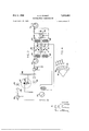
Fig. 1 1 is -=.'a. diagrammatic 1 view of a .::system:
. 3 employing conventional drum-type facsimile apparatus.
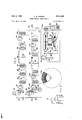
Fig. 2 illustrates a cam controlled optical generator for the transmitter and receiver of Fig. 1.
Fig. 3 illustrates'another form of variable-frequency generator that may be used in connection with the system shown in Fig. 1.
Fig. 4 is a fragmentary detail view of one the chopper discs of Fig. 3.
Figs. 5, 6 and 7 are graphs of thevoutput signals The generator shown in Fig. 2 is of the electrooptical type comprising a light source 20, a photoelectric cell 2| and interposed chopper wheel 22 and aperture plate 23 positioned to modulate the light from the source impinging upon the photocell 2|. The chopper wheel 22' is mounted on the rotating shaft 24 a'n'd" is adapted to rotate at a constant speed. The aperture plate 23 is mounted upon a shaft 25 which is arranged to obtained under certain conditions with the appa- 1 I beam directed'upon the photocell, thus increasing and decreasing the frequency of the impulses ratus of Fig. 3.
Fig. 8 illustrates a further modification.
Fig. 9 is a detail view of the optical discused in the system shown in Fig. 8.
Referring to Fig. 1, the facsimile system shown by way of examplecomprises a drum-type transmitter I0, a drum-type receiver H and a connecting wire or radio channel l2 of'any suitable'type. While the invention will be described in connecoscillate first in a clockwise and then in a countor-clockwise direction so that it alternately adds to and subtracts from the frequency of the light The result is the same as if the cell 2| and lamp 20 rotated with the shaft 25, and the plate 23 contained a tion with facsimile apparatus 'of this type for which it is essentially adapted; obviously it may be employed in many systems where trains of signals are distorted in accordance with'a prear- 1 ranged plan or coding for purposes of secrecy or other purposes.
The transmitter l0 and receiver H are each 3' 2 provided with a motor |5, [5A connected to turn a the associated drum l'6, |6A- respectively." I-n order that thedrum IBA of the receivenmay move in synchronism'with the drum I6 of the transmitter, "the motors l5 and |5A are exactlycontrolled in conventional systems to rotate uni- 3 formly atprecisely the same speed. In accordance with the present invention, the motors |5 and |5A are driven or controlled by variablefrequency impulse generators 11 and HA, which are identical and which have certain special:
characteristics as outlined below. Thus the speed of rotation'of the drum |6 is variedfrom} time to time so that the scanning rate of thetransmitted copy is varied to produce a relatively rapidand wide-range distortion" of the sig nal output. Since the drum |6A of the receiver is maintained insynchronismwith'the non-uni-' form rotative movement of the drum IS, the sig-: nals may be recorded upon the recording sheet carried by the drum ISA in such a manner that the distortion is practically eliminated and a true facsimile copy made.
In order to obtain satisfactory copies of ac'-' ceptable quality with the relatively'large distortion of the signals required for absolute secrecy, it is necessary to'match the characteristics of the generators H and HA with extreme accuracy throughout the entire transmission time and to reduce to a minimum the mechanical of impulse generators of identical construction would be employed in a complete system. One.
would be required for 'a transmitter andv one for each receiver, each. generator being like :that shown in Fig. 2.
single aperture directly in front of the cell. However, it is more convenient to employ the stationary lamp and cell, by providing a series of apertures in the aperture plateQThe variable frequency output of the cell 2| consisting of an uninterrupted train of substantially uniform pulses is amplified in an amplifier:2|, the output conductors 28 of which are connected tothe driving motor of the facsimile set.
In order to obtain a predetermined complex variation in the impulse frequency which may be accurately controlled although of relatively large magnitude and which may be duplicated in other generators of the same type, a plurality of cams 3|, 32 and 33 are provided to control the oscillation of theaperture plate '23. The cams 3|, 32 and 33 are driven by any suitable-means, such as worms 34, 35 and 36,'each engaging a'worm Wheel (shown in dotted lines) on the shaft of one of the cams.
' pairv preferably has adifferent ratio to avoid a frequent repetition ofthe distortion pattern.
The cams are further provided with cam -followers or rack members 31, 38 and 39, which are geared to the shaft 25 through differential gearing 4| and 42 whereby the angular movement of the shaft 25 is the resultant of the movements of same distortion characteristics if the sets of cams in each generator are alike and the gearing is accurately cutand-preloaded to obviate backlash. Also it will be noted that the variation 'pattern' of the impu se rate will not be repeated at frequent intervalsbecause of the use of a pluily changed.
rality of cams rotating at different speeds. If desired. new cams having different contours can be substituted from time to time for the cams 3|, 32 and 33 so that the scramblingpattern is read- The motor l5, which is driven by the output of the electro-optical generator, should be a synchronous motor and may. be of the phonic wheel type, similar to thatdisclcsed in my prior patent, Pat. No. 2,276,936, granted March 17, 1942. The rotative speed of the rotor of asynchronousmotor of this type will follow the variations in the frequency of the applied current. Therefore if the drum of the receiver is started at the same instant as the drum of the transmitter and the impulse generators are started or. released at the same instant from correspondingpositions, as disclosed rotative speeds will vary during transmission so that an unintelligible record will be received by a conventional receiver. Thus the invention pro- Each worm and worm wheel asiaaoe vides for secret" communication by' preventi-ng uniformly spaced teethoropenings, and varying the rotative speed of an aperture plate, achopper dis'c having'teeth or openings of variable spacing may. be used. This construction'simplifies-the problem of matching the characteristics of the generators at the transmitter'and receiver since the cam mechanism: is eliminated and the discs arerotate'd at a uniform. speed which may be exactly the same for each generator.
An electro-optical generator of this type 1 is illustratedin Figs. 3 and" 4. In the embodiment shown by way of illustration, two chopper wheels 55 and 36 are shown, but any desired numbermay be used, .as will'be explained. Discs A and E5 are-driven by a constant-speed motor 41, for example, at'diiferent rates through the gearing 48. Each of the chopper discs 45 and 46 is provided with a plurality ofteeth or apertures of variable spacingv arranged around the periphery of the disc. provided as indicated at'eil and 5| 'in Fig. .4, and the light source and photocell moved to a positionwhere oneor the other row of apertures is used, as desired. The distance between adjacent apertures in any particular row is variedso' that as the disc is turned at a uniform speed, the time interval between the impulses generated by the associated photo-electric means will gradually increase and decrease. Fig. 4, the distance or spacing between the successive apertures in the row 5i varies from dl to (in successively increasing steps or increments. It will be apparent that the rate of change of the spacing between the apertures is related to the rate of change in the speed of the motor driven by the optical generator.
The variably spaced apertures are laid 'out in accordance with a prearranged plan in order to obtain the desired speed variation. A master plate may be prepared by precision methods and employed to make any'number of duplicate plates, one of which is used at the transmitting station and'one at each receiving station. A separate and distinct aperture spacing plan or; layout is preferably used for each of'the rows of apertures on the different plates 45 and M3, and any other plates that may be employed:
As showninFig. 3, the chopper disc t5 is interposed between a lightsource 53 and a photocell 54 so that an uninterrupted train of frequency- Two or more rows of apertures may be Thus, as shown'in pr-ises'four'selenium rectifiers -6t,"-wnich are po1ed as well known in the art, to prevent-interaction between the two input circuits from =th'eamplifiers 5! and 581-- lnth-ismanner; the impuls'e fr'e qu'encies' are' combined andthe sumappearsin.
the secondary winding-of the transformer 63".: The average frequencies generated by-the' discs: t5 and dt may be 50-and EGG-cycles per; second respectivelygin which case a signaling-current 1 having an average frequency of 150 cycles per second may lee derivednomine -modulator 60;:
modulated electrical impulsesis generated in the output circuit of the photocell as the disc-rotates. The photocell 5% is connected to the input circuit of an amplifier 5?. Similarly the photocell 56 associated" with the second chopper disc 36 and light source 55 is connected to the input circuit of an amplifier 58.
In order to obtain a control current of varying frequency from the current-impulse trains generated by the chopper discs 45 and 36, the output circuits of the amplifiers 5? and 58 are combined in a mixeror modulator circuit 6! The modulator circuit 63 comprises input-and output transformers B2 and 63respectively, the amplifier 58 being connected to the primary winding of the transformer 6-2; and-the output of-theamplifier 51 being connected to the-centertap of the respective windings of the-transformers BZ-and 63 as-shown. The-modulator circuit fifl fur'ther com- Ifdesired, a-second modulator iiimaybe con-- nected in parallel-with-the modulator 60-; as; shown; through transformers fia and 69.- 1 The:
modulator S-lfis similar to themodulator 60, but
are connected in-such a manner that the-Outpu-t.
currents of each:modulator are 1 added=together. The total-outputcurrent-of themodulator is-impressed upen a band-pass fil-terlil which is ad dusted to pass the band-between and cycles. The-filtering and shaping circuit is conventional except for a voltage-limiter consisting of two oppositely-poled current limiting elements it, such as selenium rectifiers-Whichhave the property of'high resistance at low valuesof volt-.-
agea-nd rapidly decreasing resistance as the Voltage is increasedi This characteristic of the-voltage "limiting elements H 1 outs -off -the peaks of the 'signa-l 'waves and stabilizes the level of the. output signal. The variable-frequency output current is amplified -by an amplifier Hand used; to energize or control the-driving motor of the:
facsimile-set:
Phase shift effect in the modulating system i can be kept to aminimum by limiting thevoltages of- \both'---fr equencies* to about 0.2 volts If the voltage applied to the rectifier elementsofthe'modulator 60 is high the variable currents from the photoc ells Stand 56 may cancel each other when a -certain phase relation exists between-them-;- In thiscase, the output voltage of the transformer 63 'wil-lvary between'minimum and maXimum -val-uesas indicated by the graph 73in Fig. '5, the minimum value occurring at the point 14: Likewise the-terminal voltage across the transformer 159 will vary at the same time as indicated by the graph in Fig. 6; diminish ing at times to a'loW value as indicated at the point 18.; Sinceit is desirable to maintain the output current at a substantially constant level, the two modulators 60 and GI are connected in parallel as shown and arranged so that the voltages across both transformers 63 and 69 are added.-- This results in a substantially uniformlevel signaling current of varying frequency as indicated by the curve" in Fig. 7.
Ordinarily morethan two chopper discs would be employedin order to obtain a wider variation in the impulse rate and render the rope tition of ,the distortion pattern less: frequent.v The output currents fromleach additional. chopper Wheel would be combined withothe variable frequency current produced by the output amplifier 72 in the same manner as the output of the two photocells 54 audit are combined in the modulators 60 and BI. In this manner, a variable-frequency current having anaverage value of 200 cycles or greater may be obtained and utilized for driving a synchronous motorof 25 afacsimiletransmitter, and ail-identical current 7. derl'vedafrom a second generator-for controlling thegrecorder. 7
If desired, the Variable-frequencyoutput current-from each chopper wheel-photocell unit may be doubled before it is mixed with the current from another unit. This arrangement, which is illustrated in Fig. 8 has the advantage that therange of frequency variation is doubled and smaller discs may be used. InFig. 8 two lightmodulating discs 8I and 82 are shown although more could be employed if desired. These discs, instead of being toothed or perforated discs, are provided with alternately reflecting and nonreflecting segments, as shown in Fig. 9. These rows .of segments may be of the same width or of varying widths. In the latter case, the modulating disc would be rotated at constant speed.
However, as shown, the segments are all of the same width and'the variation in impulse frequency is obtained bymoving the light source and photocell around the axis of the rotating disc.
A frame 85, carrying the lamp-photocell unit is mounted in front of each of the discs 8|, 82,
etc. The frame 85 is pivoted on the axis of the shaft carrying the modulator disc and is oscillated back and forth by any suitable means such as by a cam 85 and link 81 pivoted at its upper end to a bar 88 carrying the frame 85. With this arrangement, it will be apparent that as the disc 8| or 82 rotates, the light reflected upon the photocell i interrupted by the non-reflecting segments of the disc and thereby an uninterrupted train of impulses is generated in the output circuit of the photocell. The oscillation of the frame 85 results in a cyclic variation of the impulse rate. The variable-frequency impulses from the photocell associated with the disc 8| are amplified in an amplifier 9| and impressed upon the frequency doubler "92. Thus, if the average frequency of the impulses in the output of the photocell is 50 cycles per second, the
output of the frequency doubler '92 will be anaverage frequency of 100 cycles per second,-varying in accordance with the variations in the original signal train. A second frequency doubler- 93 may be provided to obtain an average fre-' quency of 200 cycles per second. Each frequency doubler comprises two rectifier elements connected between input and output windings as shownto produce an alternating output voltage of double frequency. The rectifiers may be for example of the selenium-type.
The output current from-the frequency doub-' ler 93 is impressed upon a transformer 94,.the secondary winding of which is connected to=a conventional filter 95 toreduce the harmonics. The output terminals of :the filter 9-5 are connected through a transformer 96 and a voltage limiter' circuit to the control-"grid of an amplifier 9B. The limiter circuit may consist of two oppositely poled selenium rectifier elements 91, as shown. The amplified signals from the amplifier 98, through a transformer '99, are impressed upon a'second filter IN, the output of which is connected to the mixer; I02 where the signals are combined with those generated by the second photo-electric cell generator.
The signals generated by the;rotation of the disc 82 may be doubled as described above; butas shown, a different method is employed. After amplification in the amplifier I05, the signals are impressed upon a second tube I08, Which is-arranged to accentuate the third harmonic-of the fundamental frequency. For example, the-tube A9? an be a creen g d tub Whitby/operated 8 as a class B amplifier. Thus, if the variable-frequency;curr.ent.generated by the photocell unit hasanayerage frequenc of 50 cycles per second, the output current of the amplifier I86 has a large thirdharmonic' of an average frequency of 150 cycles per second. The third harmonic is passed throughthe filter I01 designed to pass the 150 cycle band, and through a transformer I68 and voltagelimiter I09, are impressed upon the control-grid of an amplifier I I0. The amplified current of an average frequency of 150' cycles per second,..througha transformer III,. is impressed ofthe stabilizer motor. as. connected toythe shaft through coupling springs I24, as more full disclosed in my prior upon fa 's'e cond. filter. I I2. Theoutput of the filter II2 isimpressed upon the mixer I02 where it is ;combined with the 200-cycle current passing through the filter IOI. The output of the mixer is filtered in the filter H3 and the 350-cycle component is amplified in. an amplifier H4 and utilized to drive a stabilizer unit I I5.
The purpose of this unit is to smooth out the V occasional turbulent variations of frequency which are of such magnitude that they might cause the synchronous driving motor of the facsimile. equipment to drop out of step. The sta 'bilizer unit isa motor-generator comprising a driving rotor II6, a flywheel Ill and a generator rotor II8 mounted for rotation on a single shaft. If additional discs similar to the discs 81 and 82 are employed, the output currents of the associated photocells are combined in the same manner as those shown and the current impressed upon the amplifier I I4..
The. output current from the amplifier I I4 travers'es. a parallel resonant circuit I I9 in series relation withvthe field magnet windings I20 and I2I The motor rotor is shown patent, No. 2,27 6,936 above referred to, which discloses the detailed construction of the motor shown as a part of the stabilizer unit. The motor circuit is'disclosed'and claimed in my prior patent, No. 2,257,158, dated September 30, 1941.
The toothed rotor II8, together with the field poles carrying windings I25 and I26, forms an inductor alternator for generating a current, the frequency of which is controlled by the rotative speed of the motor rotor H6. The frequency of the current may differ from that impressed upon the-motor, being determined by' the number of poles or teeth on the rotor I I8, and thus the stabilizer unit also serves as a frequency changer. The flywheel II'I, having considerable inertia,
serves to smooth out too rapid variations in the signal current from the amplifier H4 and, in the case of an occasional pulse of small amplitude from the mixer, maintains the rotation of the rotor I I8. Thus' the pulses from the alternator are nearly of uniform amplitude although their frequency changes in accordance with the variations produced by the electro-optical elements including discs BI and 82 because the driving motor :ltw l lbeapparent that the electro-optical g n. l
f. ndisc*"as::usiedein,connection with Fig. 3 isintendedrtoi-ncludethe useof the light-modulating frequency current to produce a distorted train of signals or impulses, varying precisely in a predetermined-manner, and to a secrecy" system utilizing such distorted signals. 1 Certain terms or phraseshave been used herein because their usuialmeaningsaptly describe: the apparatus .described. It is. notintended that these words :or
phrases beinterpreted in a restricted sense where toldo' so-wouldnnduly restrict- .the scope of the r invention. ;'The term synchronous -motor =m'eans an-alternating-current motor, the rotative speed of which isdetermined under all operating conditions by, the frequency ofthesupplycurrent and varies in accordance with fluctuations there- The phrase fchopper wheel or chopper -discs'ofFigs. 2. and,,8since-it-:-will be obvious that discs or chopperewheels of the 'difierent types illustrated all servelthe same purpose and are interchangeable.
Various modifications of the embodiments disclosed will -dccur to thoseskilledin the-art and may be made without departing from the scope of the invention.
I claim:
1. In a facsimile system for secret communication, in combination, a transmitter provided with a rotatable drum for supporting the copy or picture to be transmitted, a synchronous motor for driving said drum, scanning means associated with said drum, 2. variable-frequency generator of the pper ype connected'to said motor to vary the rotative speed of the drum and thereby distort the signal output of the transmitter as compared to a transmitter arranged to scan the copy at a uniform rate, said generator comprising a source of light, a photocell, a light chopper between said source and said photocell and means to vary the rate at which the light chopper interrupts the light on the photocell to cause an uninterrupted train of frequency-modulated impulses to be generated by the photocell, and a receiver provided with means including a second similar variable-frequency generator for correcting for the distortion of the signal output of the transmitter.
2. In a facsimile transmitter for secret com munication, in combination, a rotatable drum for supporting the copy or picture to be transmitted, a synchronous motor for driving said drum, scanning means associated with said drum and electro-optical impulse generating means connected to said motor to operate the same at variable speed, said electro-optical generating means comprising a light chopper and photocell arranged to generate an uninterrupted train of substantially uniform impulses spaced at varying predetermined intervals.
3. In a facsimile receiver for a system of the character described employing signals generated by scanning the copy at a non-uniform rate, in combination, recording mechanism, a synchronous driving motor therefor and an electro-opti- It will be cal impulse generator connected to operate said motor, said impulsegenerator comprising a rotatable variable-spacing chopper wheel arranged to generate a continuous train of frequency-modulated impulses andthereby drive the motor at a variable rotative speedcorresponding to the nonuniform rate of scanning the copy at the transmitter whereby the, recordingmech'anism.is controlled to correctthe signal distortion.
4. ,A scanning arrangement for a facsimilesystem comprising,. in combination, a rotatable scanning element, asynchronous motor for driving said rotatableelement and an electro-optical impulse generator, connected to said motor, said impulse generator. comprising aphotocell, a light chopper provided with a continuous series of apertures around theQperiphery thereof disposed in front of saidphotocell and means including said photocell and light chop er for generating an uninterrupted" train of frequency-modulated impulses adapted tofdrive the motor continuously with predetermined-fluctuations in speed and thereby vary the speed of the scanningelement.
5. A scanning arrangement for a facsimile system comprising, in combination, a rotatable scanning element, a. synchronousmotor forydriving said rotatablescanning element and, a'variablefrequency electro-optical generator connected "to said motor to impart predetermined speed variations to said scanning element, saidgenerator comprising a source of light, a photocell, a rotary chopper wheel interposed betweensaid light and .photocelland a plurality of cams arranged jointly to control the rotative speed of said chopper wheel.
6. A scanningarrangement for a facsimile system comprising, in combination, a scanning device, a member adjacent said scanning device for supporting the copy, synchronous motor means for producing relative movement between said scanning device and the copy, and a variablefrequency electro-optical impulse generator connected to said motor means to control the speed of the same, whereby to cause predetermined irregularities in the relative movement between the scanning device and the copy of relatively large magnitude, said impulse generator comprising a photocell, a light source for illuminating the cell and a rotatable chopper wheel disposed in front of said photocell to produce uninterrupted variable-rate impulse excitation of the photocell.
7. A scanning arrangement for a facsimile system comprising, in combination, a scanning device, a rotatable drum adjacent said scanning device for supporting the copy, a synchronous motor for driving the drum and a variable-frequency electro-optical impulse generator connected to said motor to control the rotative speed thereof, whereby to cause rotational variations in the movement of the drum of relatively large magnitude, said impulse generator comprising a photocell, a constant-speed chopper-wheel having a series of variably-spaced apertures around the periphery thereof and means including said photocell and chopper wheel to generate an uninterrupted train of variable-frequency current impulses.
8. In a facsimile system of the character described, a motor-driven transmitter of the drum type, a motor-driven recorder of the drum type, a transmission channel between said transmitter and said recorder, a variable-frequency alternating current generator having a frequencymodulated substantially symmetrical wave out- 11, put connected to the driving motor of the trans: mitter and a second variable-frequency alternating current generator having the same output current characteristics connected to the, driving motor of the recorder, each of said generators comprising impulse-generating means including a light-sensitive device andidentical light choppers operatively associated therewith. e
9. In a facsimile system of 'the'cha'racter described, a motor-driven transmitter of the drum type, a motor-driven recorder of'the drum type, a transmission channel between said transmitter and said recorder, a generator having a frequency-modulated substantially symmetrical wave output connected to the driving motor of the transmitter and a second substantially symmetrical wave generator having the same output current characteristics asthe .first-mentioned generator connected to the driving motor of the recorder, each of said generators comprising light-sensitive means, a plurality of chopper wheels for modulating the light impinging on said means, and means for'. combining the output currents from therespective chopper wheels;
10. In a facsimile system of the character described, a motor-driven transmitter of thedrum type, a motor-driven recorder of thedrum type, a transmission channel between said transmitter and said recorder, a generator having a frequency-modulated substantially symmetrical wave output connected to the driving motor of the transmitter and'a second generator having the same output current characteristicsas the first-mentioned generator connected to the driving motor of the recorder, each of said generators comprising a plurality of photocells, chopper REFERENCES CITED The following references are of vrecordln the file of this patent:
UNITED STATES PATENTS Number Name Date 1,164,015' Randall Dec. 14, 1915 1,475,583 Hoxie Nov. 27, 1923 1,648,687 Hoxie Nov. 8, 1927 1,727,194 Belin Sept. 3, 1929 1,885,728 Keith 2 Nov; 1, 1932 1,910,540 Hammond, Jr. May 23, 1933 1,991,522 Ranger Feb. 19, 1935 2,015,742 Cooley Oct. 1, 1935 2,108,983 Finch Feb. 22, 1938 2,265,848 Lewis Dec. 9, 1941 2,401,402 Bedford June 4, 1946 2,402,067 Mathes June 11,1946 2,406,811 Deloraine Sept.' 3, 1946 2,415,591 Hemoteau Feb. 11, 1947 2,425,076 Young Aug. 5, 1947 2,425,616 Hallborg Aug. 12, 1947 OTHER REFERENCES Electronics Magazine, April 1935, page 123.
Priority Applications (1)
| Application Number | Priority Date | Filing Date | Title |
|---|---|---|---|
| US590369A US2513402A (en) | 1945-04-26 | 1945-04-26 | Telefacsimile communication |
Applications Claiming Priority (1)
| Application Number | Priority Date | Filing Date | Title |
|---|---|---|---|
| US590369A US2513402A (en) | 1945-04-26 | 1945-04-26 | Telefacsimile communication |
Publications (1)
| Publication Number | Publication Date |
|---|---|
| US2513402A true US2513402A (en) | 1950-07-04 |
Family
ID=24361972
Family Applications (1)
| Application Number | Title | Priority Date | Filing Date |
|---|---|---|---|
| US590369A Expired - Lifetime US2513402A (en) | 1945-04-26 | 1945-04-26 | Telefacsimile communication |
Country Status (1)
| Country | Link |
|---|---|
| US (1) | US2513402A (en) |
Cited By (2)
| Publication number | Priority date | Publication date | Assignee | Title |
|---|---|---|---|---|
| US2797260A (en) * | 1952-01-30 | 1957-06-25 | Zenith Radio Corp | Subscription television system |
| US3463873A (en) * | 1966-11-30 | 1969-08-26 | Gen Dynamics Corp | Communication coding system |
Citations (16)
| Publication number | Priority date | Publication date | Assignee | Title |
|---|---|---|---|---|
| US1164015A (en) * | 1910-09-12 | 1915-12-14 | Westinghouse Electric & Mfg Co | System of electrical distribution. |
| US1475583A (en) * | 1921-05-20 | 1923-11-27 | Gen Electric | Variable-current generator |
| US1648687A (en) * | 1924-09-23 | 1927-11-08 | Gen Electric | Method and apparatus for the transmission of pictures and views |
| US1727194A (en) * | 1924-09-07 | 1929-09-03 | Belin Edouard | Electromagnetic signal transmission |
| US1885728A (en) * | 1930-06-19 | 1932-11-01 | Bell Telephone Labor Inc | Harmonic generating and selecting system |
| US1910540A (en) * | 1929-07-03 | 1933-05-23 | Jr John Hays Hammond | Secret television |
| US1991522A (en) * | 1931-03-30 | 1935-02-19 | Ranger Richard Howland | Apparatus for producing musical sounds |
| US2015742A (en) * | 1924-12-11 | 1935-10-01 | Rca Corp | Synchronizing apparatus for phototelegraphy, etc. |
| US2108983A (en) * | 1936-05-11 | 1938-02-22 | William G H Finch | Telepicture synchronizing system |
| US2265848A (en) * | 1940-07-27 | 1941-12-09 | Hazeltine Corp | Synchronizing-signal generator |
| US2401402A (en) * | 1942-08-29 | 1946-06-04 | Rca Corp | Secret communication system |
| US2402067A (en) * | 1941-10-30 | 1946-06-11 | Rca Corp | Device for secret communication |
| US2406811A (en) * | 1942-12-15 | 1946-09-03 | Standard Telephones Cables Ltd | Facsimile system |
| US2415591A (en) * | 1942-05-04 | 1947-02-11 | Henroteau Francois Char Pierre | Method and apparatus for measuring distance |
| US2425076A (en) * | 1944-02-26 | 1947-08-05 | Rca Corp | Secret facsimile system |
| US2425616A (en) * | 1943-06-19 | 1947-08-12 | Rca Corp | Facsimile synchronizing system |
-
1945
- 1945-04-26 US US590369A patent/US2513402A/en not_active Expired - Lifetime
Patent Citations (16)
| Publication number | Priority date | Publication date | Assignee | Title |
|---|---|---|---|---|
| US1164015A (en) * | 1910-09-12 | 1915-12-14 | Westinghouse Electric & Mfg Co | System of electrical distribution. |
| US1475583A (en) * | 1921-05-20 | 1923-11-27 | Gen Electric | Variable-current generator |
| US1727194A (en) * | 1924-09-07 | 1929-09-03 | Belin Edouard | Electromagnetic signal transmission |
| US1648687A (en) * | 1924-09-23 | 1927-11-08 | Gen Electric | Method and apparatus for the transmission of pictures and views |
| US2015742A (en) * | 1924-12-11 | 1935-10-01 | Rca Corp | Synchronizing apparatus for phototelegraphy, etc. |
| US1910540A (en) * | 1929-07-03 | 1933-05-23 | Jr John Hays Hammond | Secret television |
| US1885728A (en) * | 1930-06-19 | 1932-11-01 | Bell Telephone Labor Inc | Harmonic generating and selecting system |
| US1991522A (en) * | 1931-03-30 | 1935-02-19 | Ranger Richard Howland | Apparatus for producing musical sounds |
| US2108983A (en) * | 1936-05-11 | 1938-02-22 | William G H Finch | Telepicture synchronizing system |
| US2265848A (en) * | 1940-07-27 | 1941-12-09 | Hazeltine Corp | Synchronizing-signal generator |
| US2402067A (en) * | 1941-10-30 | 1946-06-11 | Rca Corp | Device for secret communication |
| US2415591A (en) * | 1942-05-04 | 1947-02-11 | Henroteau Francois Char Pierre | Method and apparatus for measuring distance |
| US2401402A (en) * | 1942-08-29 | 1946-06-04 | Rca Corp | Secret communication system |
| US2406811A (en) * | 1942-12-15 | 1946-09-03 | Standard Telephones Cables Ltd | Facsimile system |
| US2425616A (en) * | 1943-06-19 | 1947-08-12 | Rca Corp | Facsimile synchronizing system |
| US2425076A (en) * | 1944-02-26 | 1947-08-05 | Rca Corp | Secret facsimile system |
Cited By (2)
| Publication number | Priority date | Publication date | Assignee | Title |
|---|---|---|---|---|
| US2797260A (en) * | 1952-01-30 | 1957-06-25 | Zenith Radio Corp | Subscription television system |
| US3463873A (en) * | 1966-11-30 | 1969-08-26 | Gen Dynamics Corp | Communication coding system |
Similar Documents
| Publication | Publication Date | Title |
|---|---|---|
| US2391776A (en) | Intelligence transmission system | |
| US2403059A (en) | Secrecy telefacsimile system | |
| US2402067A (en) | Device for secret communication | |
| US2275974A (en) | Sweep circuit for cathode ray tube distributors | |
| US1790723A (en) | Facsimile system | |
| US2513402A (en) | Telefacsimile communication | |
| US2678347A (en) | Television control system | |
| US2409488A (en) | Facsimile communication system | |
| US2382055A (en) | Remote control system | |
| US2404566A (en) | Telephoto system | |
| US2212808A (en) | Signaling method and apparatus | |
| US1874200A (en) | Electrooptical image producing system | |
| US2052383A (en) | Synchronizing apparatus for phototelegraphy | |
| US1670375A (en) | Picture-transmitting system | |
| US2425950A (en) | Signal transmission device | |
| US2047817A (en) | Picture transmitting system | |
| US2143093A (en) | Wave generator | |
| US1885826A (en) | System of photography employing frequency modulation | |
| US1693508A (en) | Picture transmission | |
| US2439735A (en) | homrighous | |
| US2111159A (en) | Picture and sound apparatus | |
| US2707208A (en) | Secrecy facsimile system | |
| US2279242A (en) | Facsimile signal inverter | |
| US1590270A (en) | Method and apparatus for synchronizing in picture-transmission systems | |
| US2083245A (en) | Picture reproducing apparatus |