US251127A - Device foe magic lanterns - Google Patents
Device foe magic lanterns Download PDFInfo
- Publication number
- US251127A US251127A US251127DA US251127A US 251127 A US251127 A US 251127A US 251127D A US251127D A US 251127DA US 251127 A US251127 A US 251127A
- Authority
- US
- United States
- Prior art keywords
- picture
- slideways
- exhibited
- pieces
- shelf
- Prior art date
- Legal status (The legal status is an assumption and is not a legal conclusion. Google has not performed a legal analysis and makes no representation as to the accuracy of the status listed.)
- Expired - Lifetime
Links
- 241001465382 Physalis alkekengi Species 0.000 title description 2
- 230000000284 resting effect Effects 0.000 description 3
- 230000000694 effects Effects 0.000 description 1
- 230000005484 gravity Effects 0.000 description 1
- 238000004519 manufacturing process Methods 0.000 description 1
- 230000000717 retained effect Effects 0.000 description 1
Images

Classifications
-
- G—PHYSICS
- G03—PHOTOGRAPHY; CINEMATOGRAPHY; ANALOGOUS TECHNIQUES USING WAVES OTHER THAN OPTICAL WAVES; ELECTROGRAPHY; HOLOGRAPHY
- G03B—APPARATUS OR ARRANGEMENTS FOR TAKING PHOTOGRAPHS OR FOR PROJECTING OR VIEWING THEM; APPARATUS OR ARRANGEMENTS EMPLOYING ANALOGOUS TECHNIQUES USING WAVES OTHER THAN OPTICAL WAVES; ACCESSORIES THEREFOR
- G03B23/00—Devices for changing pictures in viewing apparatus or projectors
- G03B23/02—Devices for changing pictures in viewing apparatus or projectors in which pictures are removed from, and returned to, magazines; Magazines therefor
- G03B23/04—Devices for changing pictures in viewing apparatus or projectors in which pictures are removed from, and returned to, magazines; Magazines therefor with linear movement
Definitions
- the said slideways are preferably adapted to receive apieture below the 'picture which is in position to be exhibited in addition tothe one above, and the means yfor holding the pictures is such that the picture which -is in position to be exhibited and the one below it are held independently of each jother.
- the means foi ⁇ holding the pictures may be operated by hand, and-in using this pictureholder a picture is inserted in the slideways and secured in position to be exhibited, and another picture'is inserted in the slideways above it. Then the picture first insertedis released and allowed to descend by gravity out 3 5 of position, and the second picture is simultaneouslj77 allowed to descend onto the top of it, and consequently into a position to be exhibited. Then the second picture is secured in position.
- a third picture is inserted in the 4o Aslideways above it and rests on the top of the second picture, and the rst picture is released and delivered from the slideways.
- the second picture is n ext released, and it and the third are allowedto descend until the third isin 'position to be exhibited.
- a fourth picture is introduced and the second is delivered, and so on. I thus provide for arranging pic- Y tures in place so that they may be adjusted into position instantaneously.
- the pictures may be inserted ill the slideways by hand or 5o otherwise, and may be delivered into the hand or into any suitable receptacle.
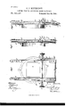
- Figure l is a back viewof a picture-holder embodying my improvements.
- Fig. 2 isacentral verticalsec- 55 tion of the same, and
- Fig. 3 is a side view thereof.
- A designates parallel open-ended slideways, 6o which are to be arranged ill an upright or approximately upright position ill a magic lantern or analogous article. They are arranged far enough apart to receive and support between them the pictures used in the magic lantern or analogous article, and they are shown as attached to a'circular plate, B, provided with an opening, a, which is designed to be located op-A posite the lens-tube ofthe magic lantern or other article.”
- ,C designates a shelf extending across the lower ends ofthe slideways A, and hinged to the forward side thereof, so that it may be turned or swung downward, as shown in Fig. 3, to perlllit pictures in the slideways to be delivered therefrom. It is preferably provided on its upper side with a facing of felt or otller soft materiahG D designates clamping-pieces arranged one ineach of the slideways, and serving to clamp 8o and hold a. picture in the slideways opposite the opening a in the plate B, so that it may be exhibited.
- clamping-pieces consist of spring-arms secured at oneA end, as here shown, the upper end to thebackor rear side of the slideways, and adapted to impinge at the other end against a picture arranged opposite the opening a ill the plate B.
- These clalnpillg-pieces alld the shelf ⁇ C may be operated in various ways to effect thefeed of the pictures.
- F desigllates arms mounted one nearthe outer side of each of the slideways A,'on a shaft, G, which extends through the slideways in rear of the guide-pieces E', and issupported thereby.
- These arms are shown as of segmental form, and they are provided with outwardly-extending pins b, which pass through slots c in rods H.
- the rods H are connected to pins d extending outwardly from the shelf C, rearward of the hinge of the latter.
- the pins b do not act upon the rods H so as to affect the shelf C when the shaft G is turned to throw or swing the said arms upward, but when the shaft G is turned in the reverse direction the said pins press the rods H downward and cause them to turn down the/shelf C. Any picture which may have been resting on the shelf will drop out of the slideways when the shelf is thus turned down.
- J designates springs connected with the pins d of the shelf (l, and with pins e extending fromthe outer sides of the slideways A. rIhese springs hold up the shelf C when it is not otherwise actuated, and by acting on the arms F through the connecting-rods H they shii't the said arms into such position that they will not interfere with the operation of the clampingpieces D. Knobs or hand-pieces G upon the ends of the shaft G forni a means whereby the shaft may be conveniently manipulated.
- the shaft Gis now turned in the reverse direction, so as to cause the vshelf C to be turned down to permit the first picture to be delivered from the slideways. This also is done during the exhibition of the second picture.
- the shaft G is now turned, as in the first instance, to cause the clamping-pieces to be swung back torelease the second picture, and thereupon the .second and third pictures descend until the third picture is in position to be exhibited. In this way the successive pictures are fed into and out of position to be exhibited, and the taneously.
- the pictures may be introduced into the slideways by hand or by means of a hopper, and may be delivered into any suitable receptacle.
- a picture-holder for a magic lantern or .analogous article the combination of slideways adapted to receive a picture in proper position to be exhibited and another picture inline with and resting upon the same, and means whereby the picture which is in position to be exhibited may be held in that position as long as desirable and then may be released, so that it will be delivered from the slideways and the other picture will drop into the proper position to be exhibited, ,substantially as specitied.
Landscapes
- Physics & Mathematics (AREA)
- General Physics & Mathematics (AREA)
- Toys (AREA)
Description
(No Model.)
E. J. MUYBRIDGE. PICTURE. EEEDINC DEVICE PCB, MAGIC LANTEENS. NC. 251,127. Patented DeC.'20,188l.
N. Finns Phnmumngmher. wnhmgwn. n4 C.
'UNITED STATES PATENT OFFICE.
.EDWARD J. MUYBRIDGD, or sAN FRANCISCO, CALIFORNIA, AssICfNonv To THE sCovILL MANUFACTURING COMPANY, or wATnnBUnY, CONN.
` PICTURE-FEEDING DEVICE FOR MAGIC'LANTERNS.
' s PECIFIcATIoN forming part'of Letters Patent No. 251,127, dated December 20,1881,
' Application filed July/2115181. (No model.)
To all whom it may concern: Be it known that I, EDWARD J. MUYBRIDGE,
. of San Francisco, in the county of San Francisco and State of California, llave invented certain new and usefullmprovements in Apparatus for Feeding' Pictures to Magic Lan! ited and another picture in line with and rest-- ing upon the same, and means whereby the picture which is in position to be exhibited may be held in that position as long as desirable and then may be released, so that it will be delivered from the slideways and the other picture will drop into the proper position 2o to be exhibited. The said slideways are preferably adapted to receive apieture below the 'picture which is in position to be exhibited in addition tothe one above, and the means yfor holding the pictures is such that the picture which -is in position to be exhibited and the one below it are held independently of each jother. i The means foi` holding the pictures may be operated by hand, and-in using this pictureholder a picture is inserted in the slideways and secured in position to be exhibited, and another picture'is inserted in the slideways above it. Then the picture first insertedis released and allowed to descend by gravity out 3 5 of position, and the second picture is simultaneouslj77 allowed to descend onto the top of it, and consequently into a position to be exhibited. Then the second picture is secured in position. A third picture is inserted in the 4o Aslideways above it and rests on the top of the second picture, and the rst picture is released and delivered from the slideways. The second picture is n ext released, and it and the third are allowedto descend until the third isin 'position to be exhibited. Then a fourth picture is introduced and the second is delivered, and so on. I thus provide for arranging pic- Y tures in place so that they may be adjusted into position instantaneously. The pictures may be inserted ill the slideways by hand or 5o otherwise, and may be delivered into the hand or into any suitable receptacle.
In the accompanying drawings, Figure l is a back viewof a picture-holder embodying my improvements. Fig. 2isacentral verticalsec- 55 tion of the same, and Fig. 3 is a side view thereof.
Similar letters of reference designate corresponding parts in all the figures.
A designates parallel open-ended slideways, 6o which are to be arranged ill an upright or approximately upright position ill a magic lantern or analogous article. They are arranged far enough apart to receive and support between them the pictures used in the magic lantern or analogous article, and they are shown as attached to a'circular plate, B, provided with an opening, a, which is designed to be located op-A posite the lens-tube ofthe magic lantern or other article."l
,C designates a shelf extending across the lower ends ofthe slideways A, and hinged to the forward side thereof, so that it may be turned or swung downward, as shown in Fig. 3, to perlllit pictures in the slideways to be delivered therefrom. It is preferably provided on its upper side with a facing of felt or otller soft materiahG D designates clamping-pieces arranged one ineach of the slideways, and serving to clamp 8o and hold a. picture in the slideways opposite the opening a in the plate B, so that it may be exhibited. These clamping-pieces consist of spring-arms secured at oneA end, as here shown, the upper end to thebackor rear side of the slideways, and adapted to impinge at the other end against a picture arranged opposite the opening a ill the plate B. The pictures, when inserted in the slideways,'pass bey tweell the forward side thereof and guide'- 9o pieces E EL These clalnpillg-pieces alld the shelf` C may be operated in various ways to effect thefeed of the pictures.
I will now proceed to vdescribe the particular lnechanism shown for operating them. F desigllates arms mounted one nearthe outer side of each of the slideways A,'on a shaft, G, which extends through the slideways in rear of the guide-pieces E', and issupported thereby. These arms are shown as of segmental form, and they are provided with outwardly-extending pins b, which pass through slots c in rods H. The rods H are connected to pins d extending outwardly from the shelf C, rearward of the hinge of the latter. Owing to the slots c the pins b do not act upon the rods H so as to affect the shelf C when the shaft G is turned to throw or swing the said arms upward, but when the shaft G is turned in the reverse direction the said pins press the rods H downward and cause them to turn down the/shelf C. Any picture which may have been resting on the shelf will drop out of the slideways when the shelf is thus turned down.
On the lower ends of the clamping-pieces D are lateral extensions, D', which pass through transverse slots s, in the outer sides of the slideways A, into the same planes as the arms F. When the shaft G is turned so that the arms I are swung upward the arms will move the clamping-pieces D backward, so that they will release any picture which may have been previously held by them.
J designates springs connected with the pins d of the shelf (l, and with pins e extending fromthe outer sides of the slideways A. rIhese springs hold up the shelf C when it is not otherwise actuated, and by acting on the arms F through the connecting-rods H they shii't the said arms into such position that they will not interfere with the operation of the clampingpieces D. Knobs or hand-pieces G upon the ends of the shaft G forni a means whereby the shaft may be conveniently manipulated.
It will be understood that when the shelf C is turned down the clamping-pieces operate to clamp and hold a picture, and that when the clamping-pieces D are caused to release a picture the shelf C is turned up to catch the pioture. rIhe slideways A are long enough to hold three pictures, one above another, and in such position that one will ibe opposite the opening a in the plate B, another below, and a third above that picture.
In using this picture-holder a picture is iirst inserted in the upper ends of the slideways, and the clamping-pieces D are moved backwardv by turning the shaft G, to allow the picture to descend to a position opposite the opening a in the plate B. Then the shaft G is released and the clamping-pieces impinge against the edge portions ofthe picture and hold it in position. A second picture is now inserted in the slideways and permitted to descend onto the top ofthe first. This may be done while the first picture is being exhibited. When the exhibition of the first picture is completed the shaft G is turned so as to cause the clamping-pieces to be swung back, and the two pictures drop downward until the first rests on the shelf C and the second one is in position to be exhib ited. rlhe change from the one picture to the .other is thus effected instantaneously,and without leaving the light from the lantern upon the scrern without a picture,so as to dazzle the eyes. As soon as the change is effected the shaft G is released and the clamping-pieces iinpinge upon and hold the. second picture. A third picture is introduced into the upper ends of the slideways and descends upon the second while the latter is being exhibited. The shaft Gis now turned in the reverse direction, so as to cause the vshelf C to be turned down to permit the first picture to be delivered from the slideways. This also is done during the exhibition of the second picture. The shaft G is now turned, as in the first instance, to cause the clamping-pieces to be swung back torelease the second picture, and thereupon the .second and third pictures descend until the third picture is in position to be exhibited. In this way the successive pictures are fed into and out of position to be exhibited, and the taneously.
The pictures may be introduced into the slideways by hand or by means of a hopper, and may be delivered into any suitable receptacle.
What I claim as my invention, and desire to secure by Letters Patent, is-
1. In a picture-holder for a magic lantern or .analogous article, the combination of slideways adapted to receive a picture in proper position to be exhibited and another picture inline with and resting upon the same, and means whereby the picture which is in position to be exhibited may be held in that position as long as desirable and then may be released, so that it will be delivered from the slideways and the other picture will drop into the proper position to be exhibited, ,substantially as specitied.
analogous article, the combination of openended slideways adapted to receive three pictures in line with each other, one in proper position to be exhibited, and one below and another above the same, and means for holding the picture which is in position to be exhibited and the one which is below it independently of each other, so that thelower may be released and delivered from the slideways While the one which is in position to be exhibited is retained there, and so that the latter may afterward be released to descend with the one above it till the latter is in position to lbe exhibited, substantially as specified.
3. In a picture-holder for a magiclantern or analogous article, the combination of the slideways A, the arms F, and the clamping-pieces D, withvtheir extensions D', substantially as specified.
4. In a picture-holder for a magic lantern or analogous article, the combination of the slideways A, the shelf C, and arms F, and the conneeting-rods H, substantially as specified.
- 5. In a picture-holder for a magic'lantern or analogous article, the combination of the slideways A, the shelf C, the connecting-rods H,
2. In a picture-holder for a magic lantern orI changes from one to another are eifected simul- IOC I ro
provided with the-slots c, and themms F, provided with the pins b, substantially as specied.
6. In a picture-holder for a magic lantern or analogous article, the combination of the slideways A, the shaft G, the arms F, connectingrods H, and thesprings J, substantially as Witnesses:
specified. FREDK. HAYNES,
7. In n.- pictureliolder for a nmgiclantern or T. J. KEANE.
analogous article, the combination of the slideio Ways A, the shelf C, the olalnping'pieces D, with their extensions D', the arms F, and the connectingmods H, substantially las specied.
EDVV. J. MUY BRIDGE.
Publications (1)
| Publication Number | Publication Date |
|---|---|
| US251127A true US251127A (en) | 1881-12-20 |
Family
ID=2320428
Family Applications (1)
| Application Number | Title | Priority Date | Filing Date |
|---|---|---|---|
| US251127D Expired - Lifetime US251127A (en) | Device foe magic lanterns |
Country Status (1)
| Country | Link |
|---|---|
| US (1) | US251127A (en) |
-
0
- US US251127D patent/US251127A/en not_active Expired - Lifetime
Similar Documents
| Publication | Publication Date | Title |
|---|---|---|
| US251127A (en) | Device foe magic lanterns | |
| US793978A (en) | Copy-holder. | |
| US1141704A (en) | Easel. | |
| US959943A (en) | Check-assorter. | |
| US595165A (en) | Magic lantern | |
| US1341666A (en) | Projection apparatus | |
| US762164A (en) | Folding photographic camera. | |
| US1341665A (en) | Projection apparatus | |
| US749048A (en) | Slide-carrier for stereopticons | |
| US181387A (en) | Improvement in machines for receiving and drying sheets from printing-presses | |
| US780590A (en) | Camera. | |
| US694080A (en) | Photographic camera. | |
| US564397A (en) | Caleb stickney | |
| US226445A (en) | Photographic stand and album | |
| US195555A (en) | Improvement in spoke-polishing machines | |
| US744928A (en) | Panoramic camera. | |
| US470783A (en) | dobbs | |
| US1041101A (en) | Book-holder. | |
| US673329A (en) | Kinetoscope. | |
| US366008A (en) | kline | |
| US900650A (en) | Photographic vignetter. | |
| US243497A (en) | Thibd to wendell zumsteg | |
| US558039A (en) | carlton | |
| US559400A (en) | tucker | |
| US150497A (en) | Improvement in photographic-printing frames |