US251095A - Weather-strip - Google Patents
Weather-strip Download PDFInfo
- Publication number
- US251095A US251095A US251095DA US251095A US 251095 A US251095 A US 251095A US 251095D A US251095D A US 251095DA US 251095 A US251095 A US 251095A
- Authority
- US
- United States
- Prior art keywords
- strip
- door
- weather
- lever
- closed
- Prior art date
- Legal status (The legal status is an assumption and is not a legal conclusion. Google has not performed a legal analysis and makes no representation as to the accuracy of the status listed.)
- Expired - Lifetime
Links
- 230000000994 depressogenic effect Effects 0.000 description 7
- 238000010009 beating Methods 0.000 description 1
- 239000000428 dust Substances 0.000 description 1
- 230000000694 effects Effects 0.000 description 1
- 230000006870 function Effects 0.000 description 1
- 239000002184 metal Substances 0.000 description 1
- 230000000284 resting effect Effects 0.000 description 1
- XLYOFNOQVPJJNP-UHFFFAOYSA-N water Substances O XLYOFNOQVPJJNP-UHFFFAOYSA-N 0.000 description 1
Images
Classifications
-
- E—FIXED CONSTRUCTIONS
- E06—DOORS, WINDOWS, SHUTTERS, OR ROLLER BLINDS IN GENERAL; LADDERS
- E06B—FIXED OR MOVABLE CLOSURES FOR OPENINGS IN BUILDINGS, VEHICLES, FENCES OR LIKE ENCLOSURES IN GENERAL, e.g. DOORS, WINDOWS, BLINDS, GATES
- E06B7/00—Special arrangements or measures in connection with doors or windows
- E06B7/16—Sealing arrangements on wings or parts co-operating with the wings
- E06B7/18—Sealing arrangements on wings or parts co-operating with the wings by means of movable edgings, e.g. draught sealings additionally used for bolting, e.g. by spring force or with operating lever
- E06B7/20—Sealing arrangements on wings or parts co-operating with the wings by means of movable edgings, e.g. draught sealings additionally used for bolting, e.g. by spring force or with operating lever automatically withdrawn when the wing is opened, e.g. by means of magnetic attraction, a pin or an inclined surface, especially for sills
Definitions
- This invention relates to an improvement in that class of weather-strips which are adapted to be attached to the bottom of outside doors as a protection against drafts, rain, dust, 850.
- the special features of my improvement consist in means whereby this hinging is effected so as to prevent the obstruction of the working of the strip by snow and ice; in means for maintaining the strip in an elevated position when the door is thrown open; in means for moving the strip to and securing it in its depressed or closed position, and for changing it from such condition to its elevated or open state, all as hereinafter more fully described.
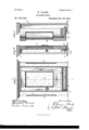
- Figure 1 is a front elevation of a door provided with my invention.
- Fig. 2 is a vertical sectionalview of the door closed, showing the strip in its depressed or closed state.
- Fig. 3 is a similar view of the door partly open, showing the strip raised;
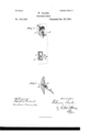
- Figs. 4 and 5 are details of the invention hereinafter described.
- A represents the door-frame, B the door, and G the door-sill.
- D designates the weather-strip, hinged or loosely hung to the face of the door upon the screws or.
- the strip is made of metal and with acurvedformation. (Shownin Figs. 2,3, and5.)
- E is a water-cap, attached to the lower por- (No model.)
- F is an opening post or projection
- G a closing-plate
- the lever H is a'spring-lever, the-outer endof which is provided with a right-angled projection, h.
- the lever H is inserted at the lower outer corner of the door, being pivoted within a frame, I. (Shown part cularly in Fig. 4.)
- the inner end of the lever is curved or made concave, and rests against a plate-spring, b, the effect of which is by hearing against the end of the le- Ver to hold it in the position to which it is brought.
- the strip D is in the raised position shown in Figs. 3 and 5, and is supported by the lever H, occupying a horizontal position, as shown in Fig. 4.
- the lever H is swung upon its hinges until the front or lower curve of the outer end of the strip strikesthe closing-plate G, attached to the inner side of the door-frame, and as the door is closed the strip is gradually depressed until it assumes the angle of the inner face of the closing-plate.
- the lever H is thrown to the position indicated in Fig.
- a particular advantage of this invention is in the mode of hanging the strip to the door, which prevents its operation being retarded by ice or snow, the connection being a free or loose one.
- This mode of hanging the strip to the door prevents friction and insures the free action of the strip when the door is opened or closed.
- Another feature of improvement is in the arrangement of the lever H, which, when the strip is closed dowp, is constructed so as not to exert any outward pressure upon the strip which would tend to deert ase the efficiency of the strip.
- Another feature is in the mode of securing the inner lower corner of the strip in its closed position by means of a stop, as described.
- Awater-eap having its lower edge turned inward, and aweather-strip loosely hung to the door and provided with an upward and outward curve, which, when the strip is depressed, forms a close joint with the inner side of the water-cap, combined with a spring-lever, the latter being adapted to support the strip in a horizontal position, and when the strip -is brought to its closed or depressed position to be removed from contact therewith, substantially as specified.
- a stop inserted at the junction of door-sill and frame, for the purpose of confining said eorner of the Weatherstrip in its closed position, substantially as specified.
Landscapes
- Engineering & Computer Science (AREA)
- Civil Engineering (AREA)
- Structural Engineering (AREA)
- Seal Device For Vehicle (AREA)
Description
(No Model.)
2 Sheets-Sheet 1.
W. CLARK.
WEATHER STRIP.
Patented Dec. 20,1881.
Q kRN (No Model.)
2 Sheets-Sheet 2 W. CLARK.
WEATHER STRIP.
No.25L095.
Patented Dec. 20,1881.
N FEYERS. Phuwumc n lur. Wnhinglnm D4 0.
UNITED STATEs PATENT Grates.
IVILLIAM CLARK, OF HAYS CITY, KANSAS.
. WEATHER-STRIP.
"SPECIFICATION forming part of Letters Patent No. 251,095, dated December. 20, 1881.
Application filed August 10, 1881.
To all whom it may concern Beit known that I, WILLIAM CLARK, a citizen of the United States, residing at Hays Uity, in the county of Ellis and State of Kansas, have invented certain new and useful Im-' I enable others skilledin the art to which it appertains to make and use the sanie, reference being bad to the accompanying drawings, and
to the letters or figures of reference marked thereomwhich form a part of this specification.
This invention relates to an improvement in that class of weather-strips which are adapted to be attached to the bottom of outside doors as a protection against drafts, rain, dust, 850.
In carrying out my invention I have endeavored to avoid com plication of par-ts and to construct the device in as simple, cheap, and durable a manner as is consistent with the functions to be performed.
- The invention relating to that class in which the strip is hinged or secured to the bottom of the door, the special features of my improvement consist in means whereby this hinging is effected so as to prevent the obstruction of the working of the strip by snow and ice; in means for maintaining the strip in an elevated position when the door is thrown open; in means for moving the strip to and securing it in its depressed or closed position, and for changing it from such condition to its elevated or open state, all as hereinafter more fully described.
In the accompanying drawings, Figure 1 is a front elevation of a door provided with my invention. Fig. 2 is a vertical sectionalview of the door closed, showing the strip in its depressed or closed state. Fig. 3 is a similar view of the door partly open, showing the strip raised; Figs. 4 and 5 are details of the invention hereinafter described.
Similar letters of reference indicate similar parts in the different figures.
A represents the door-frame, B the door, and G the door-sill.
D designates the weather-strip, hinged or loosely hung to the face of the door upon the screws or. The strip is made of metal and with acurvedformation. (Shownin Figs. 2,3, and5.)
E is a water-cap, attached to the lower por- (No model.)
tion of the door above the upper edge of the weather-strip. This cap projects forward at an angle, covering theupper edge of the weatherstrip D, the lower edge of the cap being bent inwardly, the inner edge preferably resting for support within the slots of the screws to which the weather-strip is hung. This mode of se-' curing the edge of the water-cap is, however, not essential to my invention.
F is an opening post or projection, and G a closing-plate. t I
H is a'spring-lever, the-outer endof which is provided with a right-angled projection, h. The lever H is inserted at the lower outer corner of the door, being pivoted within a frame, I. (Shown part cularly in Fig. 4.) The inner end of the lever is curved or made concave, and rests against a plate-spring, b, the effect of which is by hearing against the end of the le- Ver to hold it in the position to which it is brought.
In the description of the operation of my in vention which follows certain features not hereinbefore mentioned will be described.
Supposing the door to be open, and it is desired to close it, the strip D is in the raised position shown in Figs. 3 and 5, and is supported by the lever H, occupying a horizontal position, as shown in Fig. 4. lhe door is swung upon its hinges until the front or lower curve of the outer end of the strip strikesthe closing-plate G, attached to the inner side of the door-frame, and as the door is closed the strip is gradually depressed until it assumes the angle of the inner face of the closing-plate. At the same time the lever H is thrown to the position indicated in Fig. 2, to which it is held by its plate-spring I) out of contact with the inner portion of the weather-strip, thus relieving the strip of any pressure which wouldtend to remove it from the door-sill. At the same time the upper edge of the strip is brought in close contact with the inner side of the water-cap, thus forming a close joint, which prevents water or snow. beating under the door into the apartment. This condition of the parts is shown in Fig. 2. The lower corner of the inner end. of
the weather-stri p is confined to its closed posi- IOO tieity ofthe metallic strip permitting this movement. This end of the strip is rounded to adapt it to pass the stop 0. Supposing it is now desired to open the door, and thus bring the parts from the position shown in Fig. 2 to that shown in'Fig. 3, the door is swung back on its hinges, when the right-angled projection h of the arm H is caused to engage with the opening-post F. This contact carries the lever H up to a horizontal position, the plate-spring I) being sprung back; but the spring, by its elasticity recovering its position, holds the lever B to the horizontal position shown in Fig, 4, the lever supporting the strip D in the position shown in Figs. 3 and 5. It is thus seen that the lower edge of the strip is raised abovethe sill and opening-post F, and -that '[llGliOOl is therefore free to open.-
A particular advantage of this invention is in the mode of hanging the strip to the door, which prevents its operation being retarded by ice or snow, the connection being a free or loose one. This mode of hanging the strip to the door prevents friction and insures the free action of the strip when the door is opened or closed.
Another feature of improvement is in the arrangement of the lever H, which, when the strip is closed dowp, is constructed so as not to exert any outward pressure upon the strip which would tend to deert ase the efficiency of the strip. Another feature is in the mode of securing the inner lower corner of the strip in its closed position by means of a stop, as described.
It is evident that whenthe door is closed the rain ea'nnot beat under the door by reason of the close joints formed between the strip and sill and strip and water-cap, and that the rain is effectually shed by the angles of the cap and strip.
I claim as my inventioni 1. The combination, with a door, of a watercap, weather-strip, and spring-lever, the latter adapted to support the strip in a horizontal position, and when the strip is brought to its closed or depressed position to be removed from contact therewith, substantially as specified.
2. Awater-eap having its lower edge turned inward, and aweather-strip loosely hung to the door and provided with an upward and outward curve, which, when the strip is depressed, forms a close joint with the inner side of the water-cap, combined with a spring-lever, the latter being adapted to support the strip in a horizontal position, and when the strip -is brought to its closed or depressed position to be removed from contact therewith, substantially as specified.
3. The combination ofa weather-strip loosely hung to the door,a spring-lever having a rightangledfront projection, said lever supporting the strip when raised, and an opening-post inserted in the door-sill, operating with the rightangled projection of the spring-lever to lift the latter to its elevated position at the commencement'of the opening movement of the door, substantially as specified.
4. A water-cap and a weather-strip loosely hung to the door and having a straight exterior surface and a lower convex edge, combined with a spring-lever, an opening-post, and with an inclined closing-plate, which, when the weather-strip is closed or depressed, bears upon the straight exterior surface of the strip and presses its lower edge against the door'sill, substantially as specified.
5. In combination with a weather-strip having a lower convex surface or edge and a rounded inner corner, a stop inserted at the junction of door-sill and frame, for the purpose of confining said eorner of the Weatherstrip in its closed position, substantially as specified.
In testimony whereof 'I affix my signature in presence of two witnesses.
WILLIAM CLARK.
Witnesses:
A. M. PETRIE, HARRY 0. FREEsE.
Publications (1)
| Publication Number | Publication Date |
|---|---|
| US251095A true US251095A (en) | 1881-12-20 |
Family
ID=2320396
Family Applications (1)
| Application Number | Title | Priority Date | Filing Date |
|---|---|---|---|
| US251095D Expired - Lifetime US251095A (en) | Weather-strip |
Country Status (1)
| Country | Link |
|---|---|
| US (1) | US251095A (en) |
-
0
- US US251095D patent/US251095A/en not_active Expired - Lifetime
Similar Documents
| Publication | Publication Date | Title |
|---|---|---|
| US600301A (en) | Combined threshold and weather strip | |
| US1797839A (en) | Door seal | |
| US251095A (en) | Weather-strip | |
| US394864A (en) | Weather-strip | |
| US733295A (en) | Weather-strip. | |
| US1520584A (en) | Weather strip | |
| US583834A (en) | Weather-strip | |
| US829168A (en) | Weather-strip for doors. | |
| US319121A (en) | Weather-strip | |
| US314855A (en) | Weather-strip | |
| US619587A (en) | Weather or door strip | |
| US239049A (en) | William b | |
| US419249A (en) | Weather-strip | |
| US692014A (en) | Weather-strip. | |
| US221454A (en) | Improvement in weather-strips | |
| US328479A (en) | Weather-strip | |
| US329226A (en) | Weather-strip | |
| US483076A (en) | Weather-strip | |
| US302095A (en) | Weather-strip | |
| US860032A (en) | Weather-strip. | |
| US318437A (en) | Weather-strip | |
| US400813A (en) | Weather-strip | |
| US549448A (en) | Weather-strip | |
| US1526693A (en) | Wind and water excluder | |
| US349787A (en) | Weather-strip |