US2500176A - Drill chip breaker - Google Patents
Drill chip breaker Download PDFInfo
- Publication number
- US2500176A US2500176A US734475A US73447547A US2500176A US 2500176 A US2500176 A US 2500176A US 734475 A US734475 A US 734475A US 73447547 A US73447547 A US 73447547A US 2500176 A US2500176 A US 2500176A
- Authority
- US
- United States
- Prior art keywords
- casing
- axial
- cam
- drill
- bearings
- Prior art date
- Legal status (The legal status is an assumption and is not a legal conclusion. Google has not performed a legal analysis and makes no representation as to the accuracy of the status listed.)
- Expired - Lifetime
Links
Images

Classifications
-
- B—PERFORMING OPERATIONS; TRANSPORTING
- B23—MACHINE TOOLS; METAL-WORKING NOT OTHERWISE PROVIDED FOR
- B23B—TURNING; BORING
- B23B47/00—Constructional features of components specially designed for boring or drilling machines; Accessories therefor
- B23B47/34—Arrangements for removing chips out of the holes made; Chip- breaking arrangements attached to the tool
-
- Y—GENERAL TAGGING OF NEW TECHNOLOGICAL DEVELOPMENTS; GENERAL TAGGING OF CROSS-SECTIONAL TECHNOLOGIES SPANNING OVER SEVERAL SECTIONS OF THE IPC; TECHNICAL SUBJECTS COVERED BY FORMER USPC CROSS-REFERENCE ART COLLECTIONS [XRACs] AND DIGESTS
- Y10—TECHNICAL SUBJECTS COVERED BY FORMER USPC
- Y10T—TECHNICAL SUBJECTS COVERED BY FORMER US CLASSIFICATION
- Y10T74/00—Machine element or mechanism
- Y10T74/18—Mechanical movements
- Y10T74/18024—Rotary to reciprocating and rotary
Definitions
- the present invention relates to improvements in drill chip breakers, and has particular reference to a breaker adapted to be interposed in the rotary drive for the drill, and operable approximately once in each drill rotation to relieve momentarily over a minor portion of said rotation the axial feed pressure on the drill, whereby to permit the latter to idle or to retract out of normal position for the purpose of severing a previously formed chip curl.
- One of the objects of the invention is to provide a drill chip breaker which is unusually simple in construction, highly resistant to wear, and efficient and reliable in operation.
- Another object is to provide a drill chip breaker in which the driven element carrying the drill is supported therein for rotation and axial movement, and has a positive slot and tang rotary driving connection with the power drive element.
- a further object is to provide a drill chip breaker in which a plurality of levers revoluble with the drive element are arranged for coaction with an encircling cam to impart acentralized balanced axial thrust sustaining the driven element against the cutting reaction on the drill.
- the cam having a like number of drop grooves coacting respectively with the levers to oscillate them simultaneously once over a minor portion of each revolution whereby temporarily to relieve the axial thrust on the driven element.
- Another object is to provide a drill chip breaker in which the cam actuated levers are arranged to act against opposite ends of an equalizing'bar extending through a diametrical slot in the driven element and having a central transverse rocker edge engaging the bottom of the slot across the axis of rotation.
- Figure l is a side elevational view of a drill chip breaker embodying the features of the present invention.
- Fig. 2 is a plan view of the drill chip breaker
- Fig. 3 is a fragmentary axial sectional view taken along the line 3-3 of Fig. 2;
- Fig. 4 is a fragmentary sectional view taken along line 44 of Fig. 3;
- Fig. 5 is a view similar to Fig. 3 but illustrating the rotary elements in side elevation
- Fig. 6 is a transverse sectional view taken along line B-6 of Fig. 5, and illustrating the cam in plan.
- Fig. 7 is an enlarged section of the cam with one of the followers in engagement therewith.
- the chip breaker constituting the exemplary embodiment of the invention, comprises an outer casing in having a body section II and a flanged cover section l2 secured together in assembled relation by means of bolts 13.
- the drive element 16 has an externally tapered shank I8 adapted to be removably inserted in a complemental axial socket IS in the end of the spindle l1, and is provided at the extreme end with a diametrical driving tang 20.
- the spindle I! may be supported within the head for rotary drive and for axial feed therein or therewith.
- the sleeve bushing I4 is formed at the inner end with a peripheral flange 2
- An oil cup 23 is threaded into one side of the cover section l2, and is connected through a passage 24 to the exposed innermost face of the flange 2i, and through a branch passage 25 to a labyrinth groove 26 in the shaft portion of the drive element 16 within the bushing
- Extending rotatably and slidably through a sleeve bushing 21 fixed in a centra1 or axial opening 28 in the outer end of the body section H of the casing I0 is a driven element 29 adapted to support a rotary cutting tool, such as a drill 3B, in axial relation.
- the driven element 29 may be of any suitable character depending on the manner in which the tool 30 is to be supported, and in the present instance is shown as supporting a drill chuck 3
- the inner end of the bushing 21 is formed with an outside peripheral flange 32 which seats positively against the inner face of the contiguous end wall of the body section II, and which is disposed as a stop abutment for engagement by an enlargement or peripheral flange or rib 33 constituting a stop shoulder on the inner end of the driven element 29.
- the drive and driven shaft elements It and 29 are axially aligned, and are interconnected within the casing Ill for positive joint rotation and for relative axial sliding movement. More particularly, the driven shaft or element 29 is provided with an inward cylindrical axial extension 34 which is flattened at opposite Sides, as indicated at 35, to define a diametrical tang, and the extreme inner end of the drive element I6 is formed with a diametrical slot 36 of rectangular cross-section complemental to and slida-bly receiving the tang.
- the casing l houses a mechanism operable automatically, as an incident to-the rotation of the drive element It relative thereto, to exert an outward thrust normally maintaining the drive element 29 in projected cutting position, and to:
- the inner end portion of the drive element is peripherally enlarged to constitute. a spider 3'! which supports and revolves a plurality of levers 38 coacting with an. encircling cam element 39, and acting. on the driven element. 29. outwardly in an axial direction.
- two levers 38 located in diametrically opposite relation are provided so as to obtain a balanced centralized thrust, and each is of bell-crank type pivoted on a pin 40-withina longitudinal slot 4
- Each lever 38 has a relatively long arm 42 extending longitudinally of the slot 4i, and carrying at its end a follower roller 43. for engagement with the cam element 39, and a relatively short transverse arm or heel 44 arranged to coact with the driven shaft element 29.
- the inwardly extending radial arms 44 aredisposed in engagement with opposite ends of a transverse equalizing bar 45 extending through a diametrical slot 45 in the extension 34.
- the slot 2-5 traversesthe flatted sides 35 of the extension 34, and preferably is rectangular in crosssection and in side engagement with the bar 45.
- the lower or. outermost longitudinal edge of the bar 45 is of a wide V-shaped formto provide a transverse rocker edge 41 in direct central bearing engagement with. the bottom. surface of the slot 46 across the axis of the driven element 29.
- the outer ends of the bar 45 are notched in the top surface, indicated at 48, to. receive the ends of the arms 44 and thereby insure that the bar will be maintained in. centered position.
- the cam element 39 is held against rotation,
- the casing III is in effect supported in axially suspended relationv from the drive element I6 through engagement of the flange 2
- a bearing washer 50 is interposed between the flange 2
- the cam element 39 is seated withincomplee m'entary grooves in the contacting edge surfaces of the casing sections II and I2 concen-- trically about the axis of the-elements l 6 and 29,
- the followers 43 are staggered or offset longitudinally of the axis-of the cam element 39 so that one of the followers will contact the cam face 52 and the faceof the upper shroud ring, and the other of the followers will similarly contact the cam face and the inner surface of the lower shroud ring 56.
- the shroud rings 55 and 56 are formed in the holdout faces respectively with single clearance grooves 51 and 58 diametrically apart, and registering respectively with the drop grooves 53 and 54 in the cam face 52.
- the groove 51 will permit the upperm'ost follower roller 43.to enter the drop groove 53, and the diametrically opposite groove 58 will simultaneouslypermit the. lowermost roller to enter the drop groove54.
- the levers will be oscillated simultaneously and but once in each. revolution.
- the shroud rings 55 and.- 53 are separated from the intermediate cam face 52 by two inner peripheral grooves 59.
- Axial displacement of the follower rollers 43 may be conveniently obtained by providing rollers of like constructionv each with a reduced hub portion, and by mounting the rollers respectively in reversed position on the shaft ends of associated lever arms 42.
- the drill shifting levers 38 are symmetrically arranged with reference to the axis of revolution, and coact. with the cam. element 39 for simultaneous oscillation-to maintain an outward thrust on the driven shaft element 29 during most of each revolution, and to relieve the thrust over a minor portion of each revolution.
- the thrust is centered on the axis and accurately balanced at alltimes regardless-of the difference in effective lengths of the lever arms 42, and regardless of anymechanical aberrations in the construction.
- the tang 34 and the slot 35 afforda simple and.
- a drill chip breaker comprising, in combination, a casing having sleeve bearings fixed in and opening to opposite ends thereof, a drive shaft element journalled in one of said bearings andextending therethrough'into said casing, and being formed in the inner end with a diametrical longitudinal slot, a driven shaft element for axially supporting the drill journalled in the other of said hearings in axial alinement with said I driveelement for.
- a drill chip breaker comprising, in combination, a casing having bearings in and opening to opposite ends thereof, a drive shaft element journalled in one of said bearings and extending therethrough into said casing, and being formed in the inner end with a transverse slot, a driven shaft element for axially supporting the drill journalled in the other of said bearings in axial alinement With said drive element for rotation and axial displacement and extending therethrough into said casing, and being formed with an inner end extension slidably engaging in said slot for joint rotation in all relative axial positions, separable abutment means on said oasing and said driven element engageable to define the outermost axial stop position of said driven element, and cam-actuated means operable in response to relative rotation between said drive element and said casing for exerting a thrust to maintain said abutment means positively in engagement over the major portion of each revolution, and for releasing said thrust to permit in- Ward movement of said driven element out of said stop position over the remaining minor portion of each revolution.
- a drill chip breaker comprising, in combination, a casing having sleeve bearings fixed in and opening to opposite ends thereof, a drive shaft element journalled in one of said bearings and extending therethrough into said casing, and being formed in the inner end with a diametrical slot, a driven shaft element for axially supporting the drill journalled in the other of said bearings in axial alinement with said drive element for rotation and axial displacement and extending therethrough into said casing, and being formed with an inner axial flat extension slidably engaging in said slot, said driven element having a peripheral stop shoulder disposed for abutting engagement with a fixed stop in said casing to define the outermost axial stop position of said driven element, said extension being formed with a diametrical rectangular slot opening therethrough, an equalizer bar extending through said last mentioned slot and having a transverse rocker edge engaging the bottom surface thereof across the axis of rotation of said driven element, the opposite ends of said bar being formed in the top surface with inwardly facing notches, two bellcrank
- a drill chip breaker comprising, in com-- bination, a casing having bearings in and opening to opposite ends thereof, a drive shaft element journalled in one of said bearings and extending therethrough into said casing, and being formed in the inner end with a diametrical slot, a driven shaft element for axially supporting the drill journalled in the other of said bearings in axial alinement with said drive element for rotation and axial displacement and extending therethrough into said casing, and being formed with an inner end extension slidably engaging in said slot for joint rotation in all relative axial positions, said driven element having a peripheral stop shoulder disposed for abutting engagement with a fixed stop in said casing to define the outermost axial stop position of said driven element, said extension being formed with a diametrical slot opening therethrough, an equalizer bar extending through said last mentioned slot and having a transverse rocker engagement with the bottom surface thereof across the axis of rotation of said driven element, two bell-crank levers pivotally supported in diametrically opposed relation on said
- a drill chip breaker comprising, in combination, a casing having bearings in and opening to opposite ends thereof, a drive shaft element journalled in one of said bearings and extending therethrough into said casing, a driven shaft element for axially supporting the drill journalled in the other of said bearings in axial alinement with said drive element for rotation and axial displacement and extending therethrough into said casing, and being provided with an inner extension connected for rotary drive with and relative axial sliding adjustment to said drive element, a coacting stop on said driven element and casing for limiting outward movement of said driven element to define a normal stop position, an equalizer element extending transversely of said driven element and in rocking engagement therewith substantially on the axis of rotation, a plurality of levers pivotally supported in spaced relation on said drive element for revolution therewith and having arms extending generally inward into engagement re spectively with said equalizing element, and cam means fixed in said casing and coacting with said levers upon rotation of said drive element in said casing whereby alternatively to thrust
- a drill chip breaker comprising, in combination, a casing having bearings in and opening to opposite ends thereof, a drive shaft element journalled in one of said bearings and extending therethrough into said casing, a driven shaft element for axially supporting the tool journalled in the other of said bearings for r0- tation and axial displacement and extending therethrough into said casing, and being operatively connected to said drive element for rota-- tion therewith and axial movement relative thereto, abutment means limiting outward movement of said driven element, a circular camele ment fixed in said casing.
- a drill chip breaker comprising, in combination, a casing having hearings in and opening to opposite ends thereof, a drive element journalled in one of said bearings and extending therethrough into said casing, a driven element for axially supporting the drill journalled in the other of said bearings for rotation andaxialdisplacement and extending therethrough into said casing, and being connected with said drive element for rotation therewith and axial movement relatively thereto, means defining an axial stop position for said driven element, a circular cam element fixed in said casing and havingan annular cam face concentrically encircling said drive element and formed therein at uniformly spaced points with a plurality of drop grooves each extending through a minor portion of the circumference, a plurality of shroud rings on said cam element having annular holdout faces of substantially the same diameter as said cam face, each of said holdout faces being formed with a clearance groove, said clearance grooves being in registry respectively with said drop grooves, a plurality of levers pivotally supported on said drive element for revolution therewith
- a drill chip breaker comprising, in combination, a casing having bearings in and opening to opposite ends thereof, a drive element journalled in one of said bearings and extending therethrough into said casing, a driven element for axially supporting the drill journalled in the other of said bearings for rotation and axial displacement and extending therethrough into said casing, and being connected with said driveelement for rotation therewith andiaxial movement relatively thereto, means defining an axial stop position for said driven element, a circular cam element fixed in said casing and having an internal annular cam face concentrically encircling said drive element and formed therein at diametrically opposite points respectively with two drop grooves extending through a minor portion of the circumference, two shroud rings on said cam element having internal annular holdout faces of substantially the same diameter as-said cam face, eachof-said holdout faces being formed with a clearance groove, said two clearance grooves being in registry respectively with said drop grooves, a spider on said drive-element, two levers pivotally supported at diametrically
- a drill chip breaker comprising, in combination, a casing having bearings in and opening to opposite ends thereof, a drive element journalled in one of said" bearings and extending therethrough into said casing, a driven element for axially supporting the drill journalled in the other of said bearings for rotation and axial displacement and extending therethrough into said casing, and being connected with said drive element for rotation therewith and axial movement relatively thereto, means defining an axial stop position for said driven element, a circular cam element fixed in said casing and having an annularcam face concentrically encircling said drive element and formed therein at uniformly spaced points with a plurality of drop grooves each extending through a minor portion of the circumference, a plurality of shroud rings on said cam element having annular holdout faces, each of said holdout faces being formed with a clearance groove, said clearance grooves being in registry respectively with said drop grooves, and a plurality of levers pivotally supported on said drive element for revolution therewith and coacting with said cam face and respectively with
- a drill chip breaker comprising, in combination, a casing having bearings in and opening to opposite ends thereof, a drive element journalled in one of said bearings and extending therethrough into said casing, a driven element for axially supporting the drill journalled in the other of said bearings for rotation and axial displacement and extending therethrough into said casing, and being connected with said drive element for rotation therewith and axial movement relatively thereto, means defining an axial stop position for said driven element, a circular cam element fixed in said casing and having an annular cam facerconcentrically encircling said drive element and formed therein at uniformly spaced points with a plurality of drop rooves each extending through aminor portion of the circumference, a plurality of levers pivotally supported on said drive element for revolution therewith and coacting with said cam face and said driven element normally to urge the latter into said stop position and when engaged in said drop grooves to relieve the thrust on said driven element, and holdout means for preventing said levers from engaging in some and respectively different drop
- a drill chip breaker comprising, in combination, a casing having bearings in and opening to opposite ends thereof, a drive element journalled in one of .said bearings and extending therethrough into said casing, a driven element for axially supporting the drill journalled in the other of said bearings for rotation and axial displacement and extending therethrough into said casing, and being connected with said drive element for rotation therewith and axial movement relatively thereto, means defining an axial stop position for said driven element, a circular cam element fixed in said casing and having an annular configurated surface extending concentrically about the axis of said drive element and formed with a plurality of drop grooves in uniformly peripheral spaced relation, a plurality of levers pivotally supported on said drive element in uniformly peripheral spaced relation about said axis and having follower means coacting with said cam surface in a direction to urge said driven element into said stop position, and holdout means coacting respectively with said follower means to prevent each of said follower means individually from entering more than one of said drop grooves
- a drill chip breaker comprising, in combination, a casing having bearings in and opening to opposite ends thereof, a drive element journalled in one of said bearings and extending therethrough. into said casing, a driven element for axially supporting the drill journalled in the J Number i0 other of said bearings for rotation and axial displacement and extending therethrough into said casing, and being connected with said drive element for rotation therewith and axial movement relatively thereto, means defining an axial stop position for said driven element, a circular cam element fixed in said casing and having an internal annular configurated surface encircling the axis of said drive element, and a plurality of levers pivotally supported on said drive element in peripherally spaced relation about said axis and coasting with said cam element and said driven element in a direction to urge said driven element into said stop position, said cam element a being formed with drop grooves for simultaneous- 1y relieving said levers once during each revolution to permit movement of said driven element out of said stop position.
Description
March 14, 1950 E. HALLDEN 2,500,176
DRILL CHIP BREAKER Filed March 13, 1947 2 Sheets-Sheet 1 I 4 29 MIMI! I lg 1k BNTQ Fatentecl Mar. 14, 1950 DRILL CHIP BREAKER Erik Hallden, Detroit, Mich., assignor to Ex- Cell-O Corporation, Detroit, Mich., a corporation of Michigan Application March 13, 1947, Serial N0. 734,475
12 Claims.
The present invention relates to improvements in drill chip breakers, and has particular reference to a breaker adapted to be interposed in the rotary drive for the drill, and operable approximately once in each drill rotation to relieve momentarily over a minor portion of said rotation the axial feed pressure on the drill, whereby to permit the latter to idle or to retract out of normal position for the purpose of severing a previously formed chip curl.
One of the objects of the invention is to provide a drill chip breaker which is unusually simple in construction, highly resistant to wear, and efficient and reliable in operation.
Another object is to provide a drill chip breaker in which the driven element carrying the drill is supported therein for rotation and axial movement, and has a positive slot and tang rotary driving connection with the power drive element.
A further object is to provide a drill chip breaker in which a plurality of levers revoluble with the drive element are arranged for coaction with an encircling cam to impart acentralized balanced axial thrust sustaining the driven element against the cutting reaction on the drill. the cam having a like number of drop grooves coacting respectively with the levers to oscillate them simultaneously once over a minor portion of each revolution whereby temporarily to relieve the axial thrust on the driven element.
Another object is to provide a drill chip breaker in which the cam actuated levers are arranged to act against opposite ends of an equalizing'bar extending through a diametrical slot in the driven element and having a central transverse rocker edge engaging the bottom of the slot across the axis of rotation.
Further objects and advantages will become apparent as the description proceeds.
In the accompanying drawings:
Figure l is a side elevational view of a drill chip breaker embodying the features of the present invention;
Fig. 2 is a plan view of the drill chip breaker;
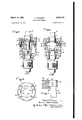
Fig. 3 is a fragmentary axial sectional view taken along the line 3-3 of Fig. 2;
Fig. 4 is a fragmentary sectional view taken along line 44 of Fig. 3;
Fig. 5 is a view similar to Fig. 3 but illustrating the rotary elements in side elevation;
Fig. 6 is a transverse sectional view taken along line B-6 of Fig. 5, and illustrating the cam in plan.
Fig. 7 is an enlarged section of the cam with one of the followers in engagement therewith.
Referring more particularly to the drawings, the chip breaker, constituting the exemplary embodiment of the invention, comprises an outer casing in having a body section II and a flanged cover section l2 secured together in assembled relation by means of bolts 13. Extending rotatably through a sleeve bushing l4 fixed in a central or axial opening IS in the cover section [2 is a rotary drive element [5 adapted for connection with and support from a spindle or quill I! incorporated in a transmission head (not shown). In the present instance, the drive element 16 has an externally tapered shank I8 adapted to be removably inserted in a complemental axial socket IS in the end of the spindle l1, and is provided at the extreme end with a diametrical driving tang 20. It will be understood that the spindle I! may be supported within the head for rotary drive and for axial feed therein or therewith.
The sleeve bushing I4 is formed at the inner end with a peripheral flange 2| seated within an annular groove 22 in the inner face of the cover section [2. An oil cup 23 is threaded into one side of the cover section l2, and is connected through a passage 24 to the exposed innermost face of the flange 2i, and through a branch passage 25 to a labyrinth groove 26 in the shaft portion of the drive element 16 within the bushing Extending rotatably and slidably through a sleeve bushing 21 fixed in a centra1 or axial opening 28 in the outer end of the body section H of the casing I0 is a driven element 29 adapted to support a rotary cutting tool, such as a drill 3B, in axial relation. The driven element 29 may be of any suitable character depending on the manner in which the tool 30 is to be supported, and in the present instance is shown as supporting a drill chuck 3| on the outer end. The inner end of the bushing 21 is formed with an outside peripheral flange 32 which seats positively against the inner face of the contiguous end wall of the body section II, and which is disposed as a stop abutment for engagement by an enlargement or peripheral flange or rib 33 constituting a stop shoulder on the inner end of the driven element 29.
The drive and driven shaft elements It and 29 are axially aligned, and are interconnected within the casing Ill for positive joint rotation and for relative axial sliding movement. More particularly, the driven shaft or element 29 is provided with an inward cylindrical axial extension 34 which is flattened at opposite Sides, as indicated at 35, to define a diametrical tang, and the extreme inner end of the drive element I6 is formed with a diametrical slot 36 of rectangular cross-section complemental to and slida-bly receiving the tang.
The casing l houses a mechanism operable automatically, as an incident to-the rotation of the drive element It relative thereto, to exert an outward thrust normally maintaining the drive element 29 in projected cutting position, and to:
relieve said thrust temporarily over a minor portion of each rotation whereby to permit adwell or slight retraction of the element sufficient to. sever the chip formed as a curhby the tool30;
during substantially the preceding portion of each rotation. In the present embodiment. of the invention, the inner end portion of the drive element is peripherally enlarged to constitute. a spider 3'! which supports and revolves a plurality of levers 38 coacting with an. encircling cam element 39, and acting. on the driven element. 29. outwardly in an axial direction. Preferably, two levers 38, located in diametrically opposite relation are provided so as to obtain a balanced centralized thrust, and each is of bell-crank type pivoted on a pin 40-withina longitudinal slot 4| in the spider 37. Each lever 38 has a relatively long arm 42 extending longitudinally of the slot 4i, and carrying at its end a follower roller 43. for engagement with the cam element 39, and a relatively short transverse arm or heel 44 arranged to coact with the driven shaft element 29.
To insure that the normally balanced thrust. jointly applied by the two levers38 will be absolutely equalized axially of the driven element 29, the inwardly extending radial arms 44 aredisposed in engagement with opposite ends of a transverse equalizing bar 45 extending through a diametrical slot 45 in the extension 34. The slot 2-5 traversesthe flatted sides 35 of the extension 34, and preferably is rectangular in crosssection and in side engagement with the bar 45. The lower or. outermost longitudinal edge of the bar 45 is of a wide V-shaped formto provide a transverse rocker edge 41 in direct central bearing engagement with. the bottom. surface of the slot 46 across the axis of the driven element 29. Preferably, the outer ends of the bar 45 are notched in the top surface, indicated at 48, to. receive the ends of the arms 44 and thereby insure that the bar will be maintained in. centered position.
The cam element 39 is held against rotation,
and, to this end, is secured rigidly withinthe casing Ill, which in turn is held against rotation by means of an arm 49 projecting externally therefrom for engagement with a suitable fixed obstruction (not shown). Also, the casing III is in effect supported in axially suspended relationv from the drive element I6 through engagement of the flange 2| with the spider 31. Preferably, a bearing washer 50 is interposed between the flange 2| and the spider 31.
The cam element 39 is seated withincomplee m'entary grooves in the contacting edge surfaces of the casing sections II and I2 concen-- trically about the axis of the-elements l 6 and 29,
and is rigidly clamped between said sections,-
When adapted for coaction With two levers 38, it is formed with aninner-peripheral-cam face diametrically opposite points.
stood that the followers 43 are normally in roll-- levers will be oscillated as the followers move into and out of the grooves 53 and 54 to permit axial retraction of the driven shaft element 29, and after a short period to return the latter to normal cutting position. Also formed in the inner surface of the annular cam element 39 and at opposite sides of the cam face 52, respectively, are two integral shroud rings55 and 56- having inner peripheral holdout faces of substantially the same diameter as the cam face 52 for preventing each of the followers 43 from entering more than one of the drop grooves 53 and 54 per revolution. Thus, the followers 43 are staggered or offset longitudinally of the axis-of the cam element 39 so that one of the followers will contact the cam face 52 and the faceof the upper shroud ring, and the other of the followers will similarly contact the cam face and the inner surface of the lower shroud ring 56. The shroud rings 55 and 56 are formed in the holdout faces respectively with single clearance grooves 51 and 58 diametrically apart, and registering respectively with the drop grooves 53 and 54 in the cam face 52. As a consequence, the groove 51 will permit the upperm'ost follower roller 43.to enter the drop groove 53, and the diametrically opposite groove 58 will simultaneouslypermit the. lowermost roller to enter the drop groove54. It willthus be evident that while the cam face is formed with two drop grooves to accommodate the two levers, the levers will be oscillated simultaneously and but once in each. revolution. Preferably, the shroud rings 55 and.- 53 are separated from the intermediate cam face 52 by two inner peripheral grooves 59. Axial displacement of the follower rollers 43 may be conveniently obtained by providing rollers of like constructionv each with a reduced hub portion, and by mounting the rollers respectively in reversed position on the shaft ends of associated lever arms 42.
It will be evident that I have produced a new and improved, drill chip breaker which is extremely simple and inexpensive in construction. The drill shifting levers 38 are symmetrically arranged with reference to the axis of revolution, and coact. with the cam. element 39 for simultaneous oscillation-to maintain an outward thrust on the driven shaft element 29 during most of each revolution, and to relieve the thrust over a minor portion of each revolution. Through the medium of the equalizing bar 45, the thrust is centered on the axis and accurately balanced at alltimes regardless-of the difference in effective lengths of the lever arms 42, and regardless of anymechanical aberrations in the construction.
The tang 34 and the slot 35 afforda simple and.
positive rotary drive connection between the drive and driven shaft elements 16 and 29, and at the same time permit free axial reciprocation of the latter under the control of the cam element 39 into and out of the normal cutting position which is determined by engagement of the shoulder 33 with the flange 32 on the bushing2'l.
I claim as my invention:
1. A drill chip breaker comprising, in combination, a casing having sleeve bearings fixed in and opening to opposite ends thereof, a drive shaft element journalled in one of said bearings andextending therethrough'into said casing, and being formed in the inner end with a diametrical longitudinal slot, a driven shaft element for axially supporting the drill journalled in the other of said hearings in axial alinement with said I driveelement for. rotationand axial displace-- ing contact with the cam face.52, and that the ,:ment and extending therethrough into said case ing, and being formed with an inner cylindrical extension with oppositely flattened sides slidably engaging in said slot, said driven element having a peripheral stop shoulder disposed for abutting engagement with the inner end of the associated bearing sleeve to define the outermost axial stop position of said driven element, and cam aotuated means operable in response to relative rotation between said drive element and said casing for exerting a thrust to maintain said driven element positively in said stop position over the major portion of each revolution, and for releasing said thrust to permit inward axial movement of said driven element out of said stop position over the remaining minor portion of each revolution.
2. A drill chip breaker comprising, in combination, a casing having bearings in and opening to opposite ends thereof, a drive shaft element journalled in one of said bearings and extending therethrough into said casing, and being formed in the inner end with a transverse slot, a driven shaft element for axially supporting the drill journalled in the other of said bearings in axial alinement With said drive element for rotation and axial displacement and extending therethrough into said casing, and being formed with an inner end extension slidably engaging in said slot for joint rotation in all relative axial positions, separable abutment means on said oasing and said driven element engageable to define the outermost axial stop position of said driven element, and cam-actuated means operable in response to relative rotation between said drive element and said casing for exerting a thrust to maintain said abutment means positively in engagement over the major portion of each revolution, and for releasing said thrust to permit in- Ward movement of said driven element out of said stop position over the remaining minor portion of each revolution.
3. A drill chip breaker comprising, in combination, a casing having sleeve bearings fixed in and opening to opposite ends thereof, a drive shaft element journalled in one of said bearings and extending therethrough into said casing, and being formed in the inner end with a diametrical slot, a driven shaft element for axially supporting the drill journalled in the other of said bearings in axial alinement with said drive element for rotation and axial displacement and extending therethrough into said casing, and being formed with an inner axial flat extension slidably engaging in said slot, said driven element having a peripheral stop shoulder disposed for abutting engagement with a fixed stop in said casing to define the outermost axial stop position of said driven element, said extension being formed with a diametrical rectangular slot opening therethrough, an equalizer bar extending through said last mentioned slot and having a transverse rocker edge engaging the bottom surface thereof across the axis of rotation of said driven element, the opposite ends of said bar being formed in the top surface with inwardly facing notches, two bellcrank levers pivotally supported in diametrically opposed relation on said drive element for revolution therewith and having relatively long arms extending generally longitudinally of said drive element and relatively short arms extending generally radially inward into engagement respectively in said notches, and cam means fixed in said casing and coacting with said long arms to oscillate said levers upon rotation of said drive element in said casing whereby alternatively to thrust said driven element into said stop position and to release said driven element for movement out of stop position.
4. A drill chip breaker comprising, in com-- bination, a casing having bearings in and opening to opposite ends thereof, a drive shaft element journalled in one of said bearings and extending therethrough into said casing, and being formed in the inner end with a diametrical slot, a driven shaft element for axially supporting the drill journalled in the other of said bearings in axial alinement with said drive element for rotation and axial displacement and extending therethrough into said casing, and being formed with an inner end extension slidably engaging in said slot for joint rotation in all relative axial positions, said driven element having a peripheral stop shoulder disposed for abutting engagement with a fixed stop in said casing to define the outermost axial stop position of said driven element, said extension being formed with a diametrical slot opening therethrough, an equalizer bar extending through said last mentioned slot and having a transverse rocker engagement with the bottom surface thereof across the axis of rotation of said driven element, two bell-crank levers pivotally supported in diametrically opposed relation on said drive element for revolution therewith and having arms engaging opposite ends of said bar, and cam means fixed in said casing and coacting with said levers to oscillate said levers upon rotation of said drive element in said casing whereby alternatively to thrust said driven element into said stop position and relieve said thrust.
5. A drill chip breaker comprising, in combination, a casing having bearings in and opening to opposite ends thereof, a drive shaft element journalled in one of said bearings and extending therethrough into said casing, a driven shaft element for axially supporting the drill journalled in the other of said bearings in axial alinement with said drive element for rotation and axial displacement and extending therethrough into said casing, and being provided with an inner extension connected for rotary drive with and relative axial sliding adjustment to said drive element, a coacting stop on said driven element and casing for limiting outward movement of said driven element to define a normal stop position, an equalizer element extending transversely of said driven element and in rocking engagement therewith substantially on the axis of rotation, a plurality of levers pivotally supported in spaced relation on said drive element for revolution therewith and having arms extending generally inward into engagement re spectively with said equalizing element, and cam means fixed in said casing and coacting with said levers upon rotation of said drive element in said casing whereby alternatively to thrust said driven element into said stop position and release said thrust.
6. A drill chip breaker comprising, in combination, a casing having bearings in and opening to opposite ends thereof, a drive shaft element journalled in one of said bearings and extending therethrough into said casing, a driven shaft element for axially supporting the tool journalled in the other of said bearings for r0- tation and axial displacement and extending therethrough into said casing, and being operatively connected to said drive element for rota-- tion therewith and axial movement relative thereto, abutment means limiting outward movement of said driven element, a circular camele ment fixed in said casing. and having an internal annular'cam face concentrically encircling said drive element and formed therein at diametrically opposite points respectively withtwo drop grooves each'extending through a minor portion of the circumference, two shroud rings on said cam element having internal annular holdout faces of substantially the same diameter as and located at opposite sides of said cam face, each of said holdout faces being formed with a clearance groove, said two clearance grooves being in registry respectively with said drop grooves, a spider on the inner end of said drive element, two bell-crank levers pivotally supported at diametrically opposite points on said spider for revolution therewith, and having relatively long arms extending generally longitudinally of said drive element, and relatively short-arms extending generally radially inward into balanced engagement with said driven element, and follower rollers on the ends of said long arms, one roller being in rolling contact with said cam face and one of said holdout faces, and the other roller being in rolling contact with said cam face and the other of said holdout faces.
'7. A drill chip breaker comprising, in combination, a casing having hearings in and opening to opposite ends thereof, a drive element journalled in one of said bearings and extending therethrough into said casing, a driven element for axially supporting the drill journalled in the other of said bearings for rotation andaxialdisplacement and extending therethrough into said casing, and being connected with said drive element for rotation therewith and axial movement relatively thereto, means defining an axial stop position for said driven element, a circular cam element fixed in said casing and havingan annular cam face concentrically encircling said drive element and formed therein at uniformly spaced points with a plurality of drop grooves each extending through a minor portion of the circumference, a plurality of shroud rings on said cam element having annular holdout faces of substantially the same diameter as said cam face, each of said holdout faces being formed with a clearance groove, said clearance grooves being in registry respectively with said drop grooves, a plurality of levers pivotally supported on said drive element for revolution therewith, and having arms extending into engagement with said driven element, and follower members 'on said levers, said members being in contact with said cam face and respectively in contact with 'said holdout faces.
8. A drill chip breaker comprising, in combination, a casing having bearings in and opening to opposite ends thereof, a drive element journalled in one of said bearings and extending therethrough into said casing, a driven element for axially supporting the drill journalled in the other of said bearings for rotation and axial displacement and extending therethrough into said casing, and being connected with said driveelement for rotation therewith andiaxial movement relatively thereto, means defining an axial stop position for said driven element, a circular cam element fixed in said casing and having an internal annular cam face concentrically encircling said drive element and formed therein at diametrically opposite points respectively with two drop grooves extending through a minor portion of the circumference, two shroud rings on said cam element having internal annular holdout faces of substantially the same diameter as-said cam face, eachof-said holdout faces being formed with a clearance groove, said two clearance grooves being in registry respectively with said drop grooves, a spider on said drive-element, two levers pivotally supported at diametrically opposite points on said spider for revolution therewith, and having first arms extending generally longitudinally of said drive element, and second arms extending into engagement with said driven element, and follower members on the ends of said first arms, one member being in contact with said cam face and one of said holdout faces, and the other member being in contact with said cam face and the other of said holdout faces.
9. A drill chip breaker comprising, in combination, a casing having bearings in and opening to opposite ends thereof, a drive element journalled in one of said" bearings and extending therethrough into said casing, a driven element for axially supporting the drill journalled in the other of said bearings for rotation and axial displacement and extending therethrough into said casing, and being connected with said drive element for rotation therewith and axial movement relatively thereto, means defining an axial stop position for said driven element, a circular cam element fixed in said casing and having an annularcam face concentrically encircling said drive element and formed therein at uniformly spaced points with a plurality of drop grooves each extending through a minor portion of the circumference, a plurality of shroud rings on said cam element having annular holdout faces, each of said holdout faces being formed with a clearance groove, said clearance grooves being in registry respectively with said drop grooves, and a plurality of levers pivotally supported on said drive element for revolution therewith and coacting with said cam face and respectively with said holdout faces to control the axial position of said driven element.
1-0. A drill chip breaker comprising, in combination, a casing having bearings in and opening to opposite ends thereof, a drive element journalled in one of said bearings and extending therethrough into said casing, a driven element for axially supporting the drill journalled in the other of said bearings for rotation and axial displacement and extending therethrough into said casing, and being connected with said drive element for rotation therewith and axial movement relatively thereto, means defining an axial stop position for said driven element, a circular cam element fixed in said casing and having an annular cam facerconcentrically encircling said drive element and formed therein at uniformly spaced points with a plurality of drop rooves each extending through aminor portion of the circumference, a plurality of levers pivotally supported on said drive element for revolution therewith and coacting with said cam face and said driven element normally to urge the latter into said stop position and when engaged in said drop grooves to relieve the thrust on said driven element, and holdout means for preventing said levers from engaging in some and respectively different drop grooves, whereby said levers will be oscillated simultaneously a predetermined number of times per revolution less than the number of said drop grooves.
11. A drill chip breaker comprising, in combination, a casing having bearings in and opening to opposite ends thereof, a drive element journalled in one of .said bearings and extending therethrough into said casing, a driven element for axially supporting the drill journalled in the other of said bearings for rotation and axial displacement and extending therethrough into said casing, and being connected with said drive element for rotation therewith and axial movement relatively thereto, means defining an axial stop position for said driven element, a circular cam element fixed in said casing and having an annular configurated surface extending concentrically about the axis of said drive element and formed with a plurality of drop grooves in uniformly peripheral spaced relation, a plurality of levers pivotally supported on said drive element in uniformly peripheral spaced relation about said axis and having follower means coacting with said cam surface in a direction to urge said driven element into said stop position, and holdout means coacting respectively with said follower means to prevent each of said follower means individually from entering more than one of said drop grooves, while permitting said follower means respectively to enter different ones of said drop grooves, whereby said levers will be simultaneously oscillated once during each revolution to relieve the thrust on said driven element.
12. A drill chip breaker comprising, in combination, a casing having bearings in and opening to opposite ends thereof, a drive element journalled in one of said bearings and extending therethrough. into said casing, a driven element for axially supporting the drill journalled in the J Number i0 other of said bearings for rotation and axial displacement and extending therethrough into said casing, and being connected with said drive element for rotation therewith and axial movement relatively thereto, means defining an axial stop position for said driven element, a circular cam element fixed in said casing and having an internal annular configurated surface encircling the axis of said drive element, and a plurality of levers pivotally supported on said drive element in peripherally spaced relation about said axis and coasting with said cam element and said driven element in a direction to urge said driven element into said stop position, said cam element a being formed with drop grooves for simultaneous- 1y relieving said levers once during each revolution to permit movement of said driven element out of said stop position.
ERIK HALLDEN.
REFERENCES CITED The following references are of record in the file of this patent:
UNITED STATES PATENTS Name Date Glassford Mar. 19, 1935 FOREIGN PATENTS Country Date Great Britain Jan. 3, 1946 Number
Priority Applications (1)
| Application Number | Priority Date | Filing Date | Title |
|---|---|---|---|
| US734475A US2500176A (en) | 1947-03-13 | 1947-03-13 | Drill chip breaker |
Applications Claiming Priority (1)
| Application Number | Priority Date | Filing Date | Title |
|---|---|---|---|
| US734475A US2500176A (en) | 1947-03-13 | 1947-03-13 | Drill chip breaker |
Publications (1)
| Publication Number | Publication Date |
|---|---|
| US2500176A true US2500176A (en) | 1950-03-14 |
Family
ID=24951844
Family Applications (1)
| Application Number | Title | Priority Date | Filing Date |
|---|---|---|---|
| US734475A Expired - Lifetime US2500176A (en) | 1947-03-13 | 1947-03-13 | Drill chip breaker |
Country Status (1)
| Country | Link |
|---|---|
| US (1) | US2500176A (en) |
Cited By (1)
| Publication number | Priority date | Publication date | Assignee | Title |
|---|---|---|---|---|
| DE1206270B (en) * | 1957-11-04 | 1965-12-02 | Hurth Masch Zahnrad Carl | Feed gear with chip breaker brake |
Citations (2)
| Publication number | Priority date | Publication date | Assignee | Title |
|---|---|---|---|---|
| US1995027A (en) * | 1932-04-22 | 1935-03-19 | Chrysler Corp | Grinding tool |
| GB574400A (en) * | 1942-08-20 | 1946-01-03 | Bastian Blessing Co | Improvements in or relating to methods of and devices or machines for drilling |
-
1947
- 1947-03-13 US US734475A patent/US2500176A/en not_active Expired - Lifetime
Patent Citations (2)
| Publication number | Priority date | Publication date | Assignee | Title |
|---|---|---|---|---|
| US1995027A (en) * | 1932-04-22 | 1935-03-19 | Chrysler Corp | Grinding tool |
| GB574400A (en) * | 1942-08-20 | 1946-01-03 | Bastian Blessing Co | Improvements in or relating to methods of and devices or machines for drilling |
Cited By (1)
| Publication number | Priority date | Publication date | Assignee | Title |
|---|---|---|---|---|
| DE1206270B (en) * | 1957-11-04 | 1965-12-02 | Hurth Masch Zahnrad Carl | Feed gear with chip breaker brake |
Similar Documents
| Publication | Publication Date | Title |
|---|---|---|
| US1907447A (en) | Flexible driving connection | |
| US1782633A (en) | Flexible driving connection for tool holders | |
| US2500176A (en) | Drill chip breaker | |
| US2673730A (en) | Spring for spring clutches | |
| US3791659A (en) | Expandable chuck or mandrel | |
| US2514759A (en) | Drill chip breaker | |
| US3904005A (en) | Overrunning clutch | |
| US1298560A (en) | Means for transmitting rotary motion. | |
| US1782272A (en) | Lathe center | |
| SE462118B (en) | SPRING DEVICE BY SYNCRONDON | |
| US2106212A (en) | Apparatus for broaching an aperture in an article relative to its outer dimension | |
| US1448157A (en) | Bearing | |
| US1564768A (en) | Chuck | |
| US2261380A (en) | Collet actuating mechanism | |
| US2295135A (en) | Contour machining tool | |
| JPH11210783A (en) | Sprag group | |
| US1764289A (en) | Spindle for chuck devices | |
| US3021733A (en) | Cutting tool | |
| US3739651A (en) | Variable speed pulley assembly | |
| US2795904A (en) | Arbor and sleeve for mounting same | |
| US2750196A (en) | Internal grip collet | |
| US2891799A (en) | Quick acting chuck | |
| US2961764A (en) | Method of making universal joint spiders | |
| US4202507A (en) | Chuck assembly | |
| US2129253A (en) | Crankshaft grinder |