US2492485A - Injection system for internal-combustion engines - Google Patents
Injection system for internal-combustion engines Download PDFInfo
- Publication number
- US2492485A US2492485A US577409A US57740945A US2492485A US 2492485 A US2492485 A US 2492485A US 577409 A US577409 A US 577409A US 57740945 A US57740945 A US 57740945A US 2492485 A US2492485 A US 2492485A
- Authority
- US
- United States
- Prior art keywords
- pressure
- fuel
- liquid
- supercharger
- exhaust
- Prior art date
- Legal status (The legal status is an assumption and is not a legal conclusion. Google has not performed a legal analysis and makes no representation as to the accuracy of the status listed.)
- Expired - Lifetime
Links
Images

Classifications
-
- F—MECHANICAL ENGINEERING; LIGHTING; HEATING; WEAPONS; BLASTING
- F02—COMBUSTION ENGINES; HOT-GAS OR COMBUSTION-PRODUCT ENGINE PLANTS
- F02D—CONTROLLING COMBUSTION ENGINES
- F02D19/00—Controlling engines characterised by their use of non-liquid fuels, pluralities of fuels, or non-fuel substances added to the combustible mixtures
- F02D19/12—Controlling engines characterised by their use of non-liquid fuels, pluralities of fuels, or non-fuel substances added to the combustible mixtures peculiar to engines working with non-fuel substances or with anti-knock agents, e.g. with anti-knock fuel
-
- Y—GENERAL TAGGING OF NEW TECHNOLOGICAL DEVELOPMENTS; GENERAL TAGGING OF CROSS-SECTIONAL TECHNOLOGIES SPANNING OVER SEVERAL SECTIONS OF THE IPC; TECHNICAL SUBJECTS COVERED BY FORMER USPC CROSS-REFERENCE ART COLLECTIONS [XRACs] AND DIGESTS
- Y02—TECHNOLOGIES OR APPLICATIONS FOR MITIGATION OR ADAPTATION AGAINST CLIMATE CHANGE
- Y02T—CLIMATE CHANGE MITIGATION TECHNOLOGIES RELATED TO TRANSPORTATION
- Y02T10/00—Road transport of goods or passengers
- Y02T10/10—Internal combustion engine [ICE] based vehicles
- Y02T10/12—Improving ICE efficiencies
Definitions
- the invention relates to apparatus for supplying a supplemental liquid, usually an antidetonant, to the fuel delivered to internal combustion engines.
- a supplemental liquid such as water or other anti-detonant
- One object of the invention is to provide an improved system for introducing the supplemental liquid into the fuel line prior to entry into the carburetor and which can be selectively controlled by the pilot through the same means used for starting and stopping the turbo-supercharger.
- Another object of the invention is to provide an improved system for injecting supplemental liquid to the fuel by which said liquid will be thoroughly mixed with the fuel in transit to the carburetor.
- Another object of the invention is to provide an improved injection system for supplemental liquid to the fuel which includes a reservoir which contains the liquid which is not under pressure and an automatically controlled pump for drawing the liquid from the reservoir and forcing it to the fuel for safe operation when the supplemental liquid contains an explosive constituent such as alcohol which is added to the water to lower the freezing point thereof to prevent freezing.
- a still further object of the invention is to provide an improved injector system for supplemental liquid to the fuel in which the speed of the supercharger is automatically increased when the injection system becomes operative.
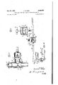
- Fig. l is a diagrammatic view of the equipment for an internal combustion engine embodying the invention.
- Fig. 2 is a section of the mixing valve for the supplemental liquid and the fuel.
- Fig. 3 is a detail, partly in section, of the ventvalve and connections for bleeding pressure from a connection communicatively connected to the exhaust pressure line used for controlling the turbo-supercharger and the anti-detonant pressure pipe.
- Fig. 4 is a detail of a modification in which the diaphragm for controlling the switch for the motor which operates the pump for the detonant is controlled by the pressure in the pipe for the exhaust gases from the turbo-supercharger.
- the invention is exemplified with equipment for an internal combustion engine which comprises: a carburetor a from which the combustible mixture is delivered to the engine cylinders in any suitable manner; a pipe b which is connected to the exhaust manifold or forms an extension thereof, through which exhaust gases flow from the engine cylinders; a turbo-supercharger which includes a turbine c driven by exhaust gases from pipe b and an air impeller or compressor d driven by said turbine; an air intake d for the impeller; a duct e between the discharge side of impeller housing d and the air intake side of the carburetor; an inter-cooler e included in duct e; a gate I buretor;
- This liquid from tank 9 is delivered to the fuel supply line 1' by a suitable pump l which has its intake connected to draw liquid through a pipe I I from supply tank Sand its discharge connected by a pipe l2 to a mixing valve l3 which is connected to the fuel supply line I.
- the mixing valve l3, as shown, is located ahead of the carburetor to effect mixing of the antidetonant with the fuel prior to entry into the carburetor and thereby effecting a beter distribution of the antl-detonant.
- Former methods for providing antl-detonant include feeding the antidetonant directly into the intake manifold. This results in poor distribution, some cylinders getting more than others, consequently resulting in overheating.
- the mixing valve l3 comprises a casing-section M which contains a check -valve I5 for preventing the flow of fuel from line 1 into the pipe l2 when there is no pressure in pipe 12.
- the mixing valve comprises a casing-section l6, containing an annular inlet member or sleeve H which is coupled to the pipe I from the booster pump m and an annular outlet member or sleeve which is coupled to the pipe 1' between valve [3 and pump m.
- members l1 and 68 are annular and tapered and have an annular space I 9 between them for producing a jet action by which water from casing I6 will be entrained with the stream of fuel flowing to pump m.
- This construction provides a valve whereby the water or anti-detonant liquid will be substantially thoroughly mixed with the liquid fuel in transit to the pump m.
- Member I! is screw-threaded to casing-section l6 and to pipe I so it can be adjusted to and from member ill for varying the area of the annular space l9 and the volume of water entrained with the fuel.
- a lock nut 20 is provided for securing member IT in its adjusted position.
- This mixing valve insures uniform and thorough mixing and prevents the feeding of alternate slugs of water and fuel to the engine.
- the fuel and anti-detonant are additionally mixed in passing through the engine-driven pump 11:.
- Pump I0 is driven by an electric motor 2
- the motoroperating circuit includes conductors 25, 26 and a relay operable switch 24.
- the coil of relay switch 24 is included in an electric circuit 23 which also includes a switch 22 for closing said circuit to actuate the relay switch 24.
- a pressure responsive device 21 which may be of the diaphragm type, is connected by a pipe 28 to the intake manifold 41 so that the diaphragm will be responsive to a predetermined increase in pressure in said manifold and is provided with a stem for closing switch 22 and causing the operation of motor 2
- Device 21 is non-responsive to fluctuations of pressure in manifold 41 during the operation of the engine 48 at normal powers, so that it will close the circuit and cause the operation of motor 2
- thepilot will 4 shift lever h slightly beyond its normal working range to cause the regulator 72 to shift gate 9 to increase the exhaust gas flow through the turbine c of the supercharger for increasing the speed of the supercharger. This enables the pilot to control the delivery of water to the fuel by the manipulation of the lever h which controls the regulator h for the turbo-supercharger.
- an increase of pressure in the manifold 41 for example, approximately one inch mercury absolute above the normal range of pressure can be utilized to control the operation of the means for delivering the water to the fuel and this can be done by the same lever or instrumentality which is used to render the regulator operative and inoperative.
- the liquid fuel is automatically leaned by the displacement of a volume of the liquid fuel with a volume of anti-detonant or water.
- the invention includes a bleedvalve 32 which is responsive to the pressure of water in the pipe 12 through which it fiows to the mixing valve l3.
- the bleeding operation causes a reduction in the actuating pressure for turbo control h, which will cause supercharger c to speed up until an increase in intake manifold pressure equal to the amount of pressure drop due to the bleed action of valve 32 is obtained.
- the bleed valve 32 comprises a chamber 30', a vent 38, and a diaphragm 3H for moving valve 30, the diaphragm 3
- a metering orifice 31 is connected to the bottom of valve 32.
- An increase of pressure in the pipe l2 while water is flowing to the mixing valve opens a line or pipe 34 to atmosphere through the metering orifice 31 and vent 38 which pipe 34 is connected at one end of the tail pipe b of the exhaust system and to the supercharger regulator 71 at its other end.
- the pressure bled from this line is dependent upon the excess boost above maximum normal power wanted.
- the means for bleeding the line comprises, in addition to the injection water operated valve 32 and the metering orifice 37 which are interposed between exhaust pressure tube 34 and the water pipe l2, a metering orifice 4
- valve 30 When valve 30 is opened by the pressure in pipe I2 acting against the bellows diaphragm some of the exhaust pressure in pipe 34 is bled off through metering orifice 37 into chamber 30' of valve 32 and out into the atmosphere through port 38.
- the by-pass altitude safety valve 45 is introduced into the bleeder system, said by-pass valve 45 comprising a housing containing a spring loaded poppet valve 44.
- the lever h In the operation of the engine for aircraft at normal speeds, for example at optimum or cruising speed, the lever h will be set in its normal operating position by the pilot to cause the regulator h to control the supercharger so that the pressure of the gases in intake manifold 41 will be insufficient to shift the diaphragm in the pressure responsive device 21, switch 22 will remain open, the relay switch 24 for the circuit for operating motor 2
- the supercharger is controlled to operate above normal speed.
- the pilot manually shifts lever it beyond its normal operating position to control the regulator h to shift gate g for an increase of approximately one inch of mercury absolute, in the pressure of the intake manifold 41.
- This will increase the speed of the supercharger and the amount of air delivered to the carburetor a.
- This increase in the speed of the turbo-supercharger will produce an increase of pressure in the intake manifold 41 and pipe 28, which will act on the diaphragm of the pressure responsive device 21 to close the circuit 23 which energizes the coil of the relay switch 24 which closes the motor circuit.
- will then drive pump Ill to force water from tank 9 via pipe l2 and under pressure to the mixing valve 13 and through check valve I5 to the annular space between members I! and I8 where the water is entrained with the liquid fuel flowing to the engine-operated pump m.
- the water will be substantially uniformly mixed A with the liquid-fuel in the mixing valve to prevent the alternate feeding of slugs of fuel and water to the pump which additionally mixes the water and fuel in transit to the carburetor.
- the displacement with water of some of the liquid fuel passing through pipe I will automatically reduce the richness of the fuel air mixture.
- the pilot When the engine is to be operated within normal power ranges without the addition of water to the fuel, the pilot will set the lever h for controlling the regulator h. for the operation of the turbine c of the turbo-supercharger at a speed which will produce sufficient pressure in the intake manifold 41 to permit the diaphragm 21 to open switch 22 for opening the relay switch 24 and stopping the motor 2
- the pressure drop in pipe l2 resulting from the stopping of the pump will permit check valve 30 to close and discontinue the bleeding of pressure from the pipe 34, thereby cutting supercharger speed and lowering manifold pressure.
- the engine will then be operated without anti-detonant or water from tank 9 until the pilot again sets the supercharger regulator to produce the necessary predetermined increase in pressure in the intake manifold 41 for starting the water injection system.
- reservoir for the supplemental liquid means for forcing the liquid to the fuel for delivery to the engine; means for bleeding pressure from the line to the regulator for varying the speed of the supercharger, and means responsive to the pressure of the supplemental liquid passing to the fuel for controlling the bleed-means.
- Apparatus for supplying a supplemental liquid to the fuel for use in operating an internal combustion engine equipped with a turbo-supercharger driven by exhaust from the engine, a regulator for the turbo-supercharger, responsive to manifold pressure, a pressure line associated with the regulator, and means for controlling the operation of the regulator comprising: a reservoir for the supplemental liquid; means for forcing the liquid to the fuel for delivery to the engine; means for bleeding pressure from the line to the regulator for varying the speed of the supercharger; and means for controlling the regulator including a vent for bleeding pressure from the exhaust, and means responsive to pressure of the supplemental liquid, passing to the fuel, for controlling the vent.
- Apparatus for supplying a supplemental liquid to the fuel for use in operating an internal combustion engine equipped with a turbo-supercharger driven by exhaust from the engine, a regulator for the turbo-supercharger responsive to pressure of the exhaust, and means for controlling the operation of the regulator comprising: a reservoir for the supplemental liquid; means for forcing the liquid to the fuel for delivery to the engine; means responsive to the pressure of the intake manifold for controlling the delivery of the supplemental liquid to the fuel; means for bleeding pressure from the exhaust; and means responsive to the pressure of the supplemental liquid passing to the fuel for controlling the bleed-means.
- Apparatus for supplying a supplemental liquid to the fuel for use in operating an internal combustion engine equipped with a turbo-supercharger driven by exhaust from the engine, a regulator for the turbo-supercharger responsive to pressure of the exhaust, and means for controlling the operation of the regulator comprising: a reservoir for the supplemental liquid; means for forcing the liquid to the fuel for delivery to the engine; means responsive to the pressure of the intake manifold for controlling the delivery of the supplemental liquid to the fuel; means for bleeding fluid from the exhaust; and means for controlling the regulator including a vent for bleeding fluid from the exhaust, and means responsive to pressure of the supplemental liquid flowing to the fuel, for controlling the vent.
- Apparatus for supplying a supplemental liquid to the fuel for use in operating an internal combustion engine equipped with a carburetor, a turbo-supercharger driven by exhaust from the engine, a regulator for the turbo-supercharger responsive to pressure of the exhaust, and means for controlling the operation of the regulator comprising: a reservoir for the supplemental liquid; means for forcing the liquid to the fuel for delivery to the engine; meansresponsive to the pressure of the intake manifold for controlling the delivery of the supplemental liquid to the fuel; a duct connected to the exhaust, a
- Apparatus for supplying a supplemental liquid to liquid fuel for use in operating an internal combustion engine equipped with a turbosupercharger, an exhaust pipe from the engine to the supercharger, a regulator for the supercharger connected to the exhaust duct and responsive to the pressure in said pipe, and means for controlling the operation of the regulator comprising: means for delivering the supplemental liquid to the fuel for delivery to the engine; means controlled by a predetermined increase of the pressure of the exhaust in said duct for controlling the operation of the liquid delivery means; a duct connected and responsive to the pressure of the exhaust flowing to the regulator; a vent for bleeding fluid from the regulator duct; and means responsive to the pressure of the supplemental liquid for controlling the vent.
- Apparatus for supplying a supplemental liquid to liquid fuel for use in operating an internal combustion engine equipped with a carburetor, a turbo-supercharger, an exhaust pipe from the engine to the supercharger, a regulator for the supercharger connected to the exhaust duct and responsive to the pressure in said pipe, and means for controlling the operation of the regulator comprising: means for delivering the supplemental liquid to the fuel for delivery to the engine; means controlled by a predetermined increase of the pressure of the exhaust for controlling the operation of the liquid delivery means; a duct connected to the exhaust flowing to the regulator and to the air being delivered to the carburetor; a vent for bleeding fluid from the duct; and means responsive to the pressure of the supplemental liquid for controlling the vent.
- Apparatus for supplying a supplemental liquid to the fuel used in operating an internal combustion engine equipped with a turbo-supercharger driven by exhaust from the engine, and means for controlling the speed of the supercharger comprising: a reservoir for the supplemental liquid; a pump for drawing liquid from the reservoir and forcing it to the fuel; a motor for driving the pump; and means responsive to a predetermined increase in the pres-sure of the exhaust to the turbo-supercharger, for controlling the operation of the motor to drive the pump and the delivery of the supplemental liquid to the fuel.
- Apparatus for supplying a supplemental liquid to the fuel used in operating an internal combustion engine equipped with a turbo-supercharger driven by exhaust from a pipe from the engine, and means for controlling the speed of the supercharger comprising: a reservoir for the supplemental liquid; a pump for drawing liquid from the reservoir and forcing it to the fuel; a motor for driving the pump; and means responsive to a predetermined increase in the pressure in said pipe for controlling the operation of the motor to drive the pump and the delivery of the liquid to the fuel.
- Apparatus for supplying a supplemental liquid to the fuel used in operating an internal combustoin engine equipped with an exhaust duct from the engine, and means for controlling the pressure in the exhaust duct comprising: a reservoir for said liquid; a pump for drawing liquid from the pump and forcing it to the fuel; a motor for operating said pump; and fluid pressure means responsive to variations in the pressure in the exhaust from the engine for starting and stopping the motor and the pump, to control the delivery of liquid to the fuel.
- Apparatus for supplying supplemental liquid fuel used in operating an internal combustion engine provided with means for delivering liquid fuel under pressure for the operation of the engine comprising: a reservoir for the supplemental liquid; a pump for drawing liquid from the reservoir and forcing it to the fuel; a motor for driving said pump; a mixing valve between said pump and the fuel delivery means, and means responsive to predetermined increase in pressure of the exhaust from the engine, for controlling the operation of the motor.
- Apparatus for supplying supplemental liquid to'fuel used in operating an internal combustion engine provided with means for delivering liquid fuel under pressure for the operation of the engine comprising: a reservoir for the supplemental liquid; a pump for drawing liquid from the reservoir and forcing it to the fuel; a motor for driving said pump; a mixing valve between said pump and the fuel delivery means, said valve comprising annular inlet and discharge members with an annular gap between them through which the supplemental liquid flows to the fuel, and means responsive to a predeter-' mined increase in pressure of the exhaust from the engine, for controlling the operation of the motor.
- Apparatus for supplying supplemental liquid to fuel used in operating an internal combustion engine provided with means for delivering liquid fuel under pressure for the operation of the engine comprising: a reservoir for the supplemental liquid; a pump for drawing liquid from 10 operation of the motor, responsive to a predetermined increase in pressure in the exhaust pipe from the engine.
- Apparatus for supplying supplemental liquid to fuel used in operating an internal com- I bustion engine provided with means for delivering fuel under pressure to the engine, a turbos'upercharger, and an exhaust duct between the engine and the supercharger, comprising: a reservoir for the supplemental liquid; means for delivering liquid from the reservoir to the fuel; and means, responsive to the pressure of the liquid passing to the fuel, for bleeding exhaust from said exhaust duct and varying the speed of the turbo-supercharger.
- Apparatus liquid to fuel used in operating an internal combustion engine provided with means for delivering fuel under pressure to the engine, a turbosupercharger, and an exhaust duct between the engine and the supercharger comprising: a reservoir for the supplemental liquid; means for delivering liquid from the reservoir to the fuel; a connection for discharging fluid from such exhaust duct, including a vent-valve, and means responsive to the pressure of the liquid passing to the fuel for controlling said valve.
- a motor I for driving said pump; a mixing valve between said pump and the fuel-delivery means; means for adlusting the valve to vary the volume of liquid mixed with the fuel; and means responsive to a predetermined increase in pressure of the exhaust from the engine, for controlling the operation of the motor.
- Apparatus for supplying supplemental liquid to fuel used in operating an internal combustion engine provided with means for delivering liquid fuel under pressure to the engine, a turbo-supercharger and an exhaust pipe from the engine to the supercharger comprising: a reservoir for the supplemental liquid; a pump for drawing supplemental liquid from the reservoir and forcing it to the fuel; a motor for driving 0 1,803,097
- Apparatus for supplying supplemental liquid to fuel used in operating an internal combustion engine provided with means for delivering fuel under pressure to the engine, a turbosupercharger, and an exhaust duct between the engine and the supercharger comprising: a reservoir for the supplemental liquid; means for delivering liquid from the reservoir tothe fuel:
- connection for discharging fluid from said ex haust duct including a vent-valve and a flxed leak-orifice, for controlling the discharge of exhaust fluid from the exhaust duct, and means responsive to the pressure of the liquid passing to the fuel, for controlling said valve.
Description
2,492,485 INJECTION SYSTEM FOR INTERNAL-COMBUSTION ENGINES Filed Feb. ;2, 1945 H. F. KING Dec. 2'7,v 1949 2 Sheets-Sheet 1 I H. F. KING Dec. 27 1949 INJECTION SYSTEM FOR INTERNAL-COMBUSTION ENGINES 2 Sheets-Shet 2 Filed Feb. l2, 1945 IN VEN T06. ward.
III
Patented Dec'. 27, 1949 S PATENT OFFICE INJECTION SYSTEM FOR INTERNAL- COMBUSTION ENGINES Howard F. King, Coronado, Calii'., assignor to Consolidated Vultee Aircraft Corporation, San Diego, Calif., a corporation of Delaware Application February 12, 1945, Serial No. 577,409
17 Claims. 1
The invention relates to apparatus for supplying a supplemental liquid, usually an antidetonant, to the fuel delivered to internal combustion engines.
In the operating of supercharged internal combustion engines used on aircraft it has been found advantageous to inject a supplemental liquid, such as water or other anti-detonant, to the fuel delivered to the carburetor when the engine is operated at predetermined high speeds for takeoff, climbing or other emergency operations.
One object of the invention is to provide an improved system for introducing the supplemental liquid into the fuel line prior to entry into the carburetor and which can be selectively controlled by the pilot through the same means used for starting and stopping the turbo-supercharger.
Another object of the invention is to provide an improved system for injecting supplemental liquid to the fuel by which said liquid will be thoroughly mixed with the fuel in transit to the carburetor.
Another object of the invention is to provide an improved injection system for supplemental liquid to the fuel which includes a reservoir which contains the liquid which is not under pressure and an automatically controlled pump for drawing the liquid from the reservoir and forcing it to the fuel for safe operation when the supplemental liquid contains an explosive constituent such as alcohol which is added to the water to lower the freezing point thereof to prevent freezing.
A still further object of the invention is to provide an improved injector system for supplemental liquid to the fuel in which the speed of the supercharger is automatically increased when the injection system becomes operative.
Other objects of the invention will appear from the detailed description.
The invention consists in the several novel features hereinafter set forth and more particularly defined by claims at the conclusion hereof.
In the drawings:
Fig. l is a diagrammatic view of the equipment for an internal combustion engine embodying the invention.
Fig. 2 is a section of the mixing valve for the supplemental liquid and the fuel.
Fig. 3 is a detail, partly in section, of the ventvalve and connections for bleeding pressure from a connection communicatively connected to the exhaust pressure line used for controlling the turbo-supercharger and the anti-detonant pressure pipe.
Fig. 4 is a detail of a modification in which the diaphragm for controlling the switch for the motor which operates the pump for the detonant is controlled by the pressure in the pipe for the exhaust gases from the turbo-supercharger.
The invention is exemplified with equipment for an internal combustion engine which comprises: a carburetor a from which the combustible mixture is delivered to the engine cylinders in any suitable manner; a pipe b which is connected to the exhaust manifold or forms an extension thereof, through which exhaust gases flow from the engine cylinders; a turbo-supercharger which includes a turbine c driven by exhaust gases from pipe b and an air impeller or compressor d driven by said turbine; an air intake d for the impeller; a duct e between the discharge side of impeller housing d and the air intake side of the carburetor; an inter-cooler e included in duct e; a gate I buretor;
g at the discharge terminal of the turbine c by which the volume of the exhaust gases flowing through said turbine can be controlled for varying the speed of the impeller in housing d and the volume of air flowing through duct e to the cara supercharger-regulator h which is adapted to shift the gate g through a link and crank connection 9 which is connected by pipes h to oil under engine-system pressure for rendering the regulator responsive to such pressure; a tube 34 between the exhaust pipe b and the regulator h for rendering the regulator responsive to variations of pressure in the exhaust pipe b; and lever h shiftable by the pilot or operator, and a connection h operable by lever h for rendering the regulator operative for regulated control of the speed of the turbine and rendering it inoperative because of the by-passing of the gases through the tailpipe rather than the passing thereof through the wheel of the turbine; a supply line I for liquid fuel to which the fuel is delivered by a booster pump m; an engine driven pump m connected to line I for delivering the fuel to the carburetor a; and a tank or reservoir 9 for a supply of anti-detonant, such as water or other suitable mixture, for selective operation of 3 alumina silicates, both natural and synthetic, may be employed. This liquid from tank 9 is delivered to the fuel supply line 1' by a suitable pump l which has its intake connected to draw liquid through a pipe I I from supply tank Sand its discharge connected by a pipe l2 to a mixing valve l3 which is connected to the fuel supply line I. The mixing valve l3, as shown, is located ahead of the carburetor to effect mixing of the antidetonant with the fuel prior to entry into the carburetor and thereby effecting a beter distribution of the antl-detonant. Former methods for providing antl-detonant include feeding the antidetonant directly into the intake manifold. This results in poor distribution, some cylinders getting more than others, consequently resulting in overheating. Another method was to feed directly into the cylinder intake valve ports; the system for doing so is very complicated and furthermore it is difficult to control the amount of antidetonant that is fed to each cylinder. The pump may have a capacity of 200 gallons per hour at a pressure ranging from 2 to pounds. The mixing valve l3 comprises a casing-section M which contains a check -valve I5 for preventing the flow of fuel from line 1 into the pipe l2 when there is no pressure in pipe 12. The mixing valve comprises a casing-section l6, containing an annular inlet member or sleeve H which is coupled to the pipe I from the booster pump m and an annular outlet member or sleeve which is coupled to the pipe 1' between valve [3 and pump m. The contiguous ends of members l1 and 68 are annular and tapered and have an annular space I 9 between them for producing a jet action by which water from casing I6 will be entrained with the stream of fuel flowing to pump m. This construction provides a valve whereby the water or anti-detonant liquid will be substantially thoroughly mixed with the liquid fuel in transit to the pump m. Member I! is screw-threaded to casing-section l6 and to pipe I so it can be adjusted to and from member ill for varying the area of the annular space l9 and the volume of water entrained with the fuel. A lock nut 20 is provided for securing member IT in its adjusted position. This mixing valve insures uniform and thorough mixing and prevents the feeding of alternate slugs of water and fuel to the engine. The fuel and anti-detonant are additionally mixed in passing through the engine-driven pump 11:.
Pump I0 is driven by an electric motor 2| which is automatically controlled by the pressure of the charge in the intake manifold 41. The motoroperating circuit includes conductors 25, 26 and a relay operable switch 24. The coil of relay switch 24 is included in an electric circuit 23 which also includes a switch 22 for closing said circuit to actuate the relay switch 24. A pressure responsive device 21 which may be of the diaphragm type, is connected by a pipe 28 to the intake manifold 41 so that the diaphragm will be responsive to a predetermined increase in pressure in said manifold and is provided with a stem for closing switch 22 and causing the operation of motor 2| and pump Ill to deliver liquid from tank 9 to mixing valve l3. Device 21 is non-responsive to fluctuations of pressure in manifold 41 during the operation of the engine 48 at normal powers, so that it will close the circuit and cause the operation of motor 2| and pump Ill only when said pressure is selectively exceeded. When it is desired to supply water to the fuel thepilot will 4 shift lever h slightly beyond its normal working range to cause the regulator 72 to shift gate 9 to increase the exhaust gas flow through the turbine c of the supercharger for increasing the speed of the supercharger. This enables the pilot to control the delivery of water to the fuel by the manipulation of the lever h which controls the regulator h for the turbo-supercharger. In practice, an increase of pressure in the manifold 41, for example, approximately one inch mercury absolute above the normal range of pressure can be utilized to control the operation of the means for delivering the water to the fuel and this can be done by the same lever or instrumentality which is used to render the regulator operative and inoperative.
The liquid fuel is automatically leaned by the displacement of a volume of the liquid fuel with a volume of anti-detonant or water.
To cause supercharger c to operate beyond its normal speed the invention includes a bleedvalve 32 which is responsive to the pressure of water in the pipe 12 through which it fiows to the mixing valve l3. The bleeding operation causes a reduction in the actuating pressure for turbo control h, which will cause supercharger c to speed up until an increase in intake manifold pressure equal to the amount of pressure drop due to the bleed action of valve 32 is obtained. The bleed valve 32 comprises a chamber 30', a vent 38, and a diaphragm 3H for moving valve 30, the diaphragm 3| being operable in response to the water pressure in the pipe 52. A metering orifice 31 is connected to the bottom of valve 32. An increase of pressure in the pipe l2 while water is flowing to the mixing valve opens a line or pipe 34 to atmosphere through the metering orifice 31 and vent 38 which pipe 34 is connected at one end of the tail pipe b of the exhaust system and to the supercharger regulator 71 at its other end. The pressure bled from this line is dependent upon the excess boost above maximum normal power wanted.
The means for bleeding the line comprises, in addition to the injection water operated valve 32 and the metering orifice 37 which are interposed between exhaust pressure tube 34 and the water pipe l2, a metering orifice 4| with a parallel bypassing altitude safety valve 45, serially connected into exhaust pressure tube 34. When valve 30 is opened by the pressure in pipe I2 acting against the bellows diaphragm some of the exhaust pressure in pipe 34 is bled off through metering orifice 37 into chamber 30' of valve 32 and out into the atmosphere through port 38. Before the exhaust gases in pipe 34 reach orifice 31 they are metered through a primary metering orifice 4| in by-pass pipe 42, said orifice 4i acting as a restrictor to limit the volume flow of gases into that section of pipe 34 which is connected to the supercharger regulator h, so that a relatively small bleed opening in orifice 31 will suffice to accomplish the required pressure drop before the exhaust gas pressures reach the supercharger regulator h. In order to prevent excessive supercharger speeds during high altitude operation, the by-pass altitude safety valve 45 is introduced into the bleeder system, said by-pass valve 45 comprising a housing containing a spring loaded poppet valve 44. During high altitude operation the absolute pressure in the exhaust pipe and the turbo supercharger control pipe 34 remains substantially the same as at low altitude operation; however the atmospheric back pressure acting against orifice 31 through port 38 when valve 30 is open is greatly reduced so that there is a great pressure differential between the two sides of the metering orifice 31 which results in increased bleeding off of pressure delivered to the supercharger control beyond the desired amount, thereby effecting undesirable supercharger speeds. By-pass valve 44 prevents this condition by causing spring loaded poppet 45 to open and thereby allowing additional exhaust gas to be delivered to bleed orifice 31, and thus maintaining substantially equal pressure on the supercharger regulator h at all altitudes.
The operation will be as follows: In the operation of the engine for aircraft at normal speeds, for example at optimum or cruising speed, the lever h will be set in its normal operating position by the pilot to cause the regulator h to control the supercharger so that the pressure of the gases in intake manifold 41 will be insufficient to shift the diaphragm in the pressure responsive device 21, switch 22 will remain open, the relay switch 24 for the circuit for operating motor 2| will be open, the pump Ill will be idle, and no water will be pumped from tank 9 to the mixing chamber l3 or to the fuel delivered to the carburetor a by pump m. There will be no water pressure from pipe l2 against diaphragm 3! so that vent-valve 30 in casing 32 will be closed and there will be no bleeding of pressure from the pipe 34 and no increase in supercharger speed. The engine will then operate without anti-detonant or water.
During take-off, or a climb of the aircraft, the supercharger is controlled to operate above normal speed. For this purpose the pilot manually shifts lever it beyond its normal operating position to control the regulator h to shift gate g for an increase of approximately one inch of mercury absolute, in the pressure of the intake manifold 41. This will increase the speed of the supercharger and the amount of air delivered to the carburetor a. This increase in the speed of the turbo-supercharger will produce an increase of pressure in the intake manifold 41 and pipe 28, which will act on the diaphragm of the pressure responsive device 21 to close the circuit 23 which energizes the coil of the relay switch 24 which closes the motor circuit. Motor 2| will then drive pump Ill to force water from tank 9 via pipe l2 and under pressure to the mixing valve 13 and through check valve I5 to the annular space between members I! and I8 where the water is entrained with the liquid fuel flowing to the engine-operated pump m. The water will be substantially uniformly mixed A with the liquid-fuel in the mixing valve to prevent the alternate feeding of slugs of fuel and water to the pump which additionally mixes the water and fuel in transit to the carburetor. The displacement with water of some of the liquid fuel passing through pipe I will automatically reduce the richness of the fuel air mixture.
While water under pressure is being forced to the mixing valve 13, diaphragm 3| will be operated to open vent-valve 30. Pressure will then be bled from pipe 34 which is connected to the exhaust gas in duct 1). The amount of pressure bled from pipe 34 is dependent upon the increase in pressure developed by the engine in the exhaust pipe b over the normal take-off or emergency power. This venting will cause the turbosupercharger regulator h to shift the gate g to cause the speed of the turbo-supercharger to be increased to compensate for the loss of pressure in tail pipe b. This bleeding of pressure will 6 continue until the fluid from tank 9 has been exhausted or the control lever h is restored to its setting for controlling the regulator for operation of the engine at normal speed.
If the water in tank 9 becomes exhausted, the pump ill, which is of a type which will not produce pressure without the presence of liquid, will no longer produce pressure in pipe l2 and diaphragm 3| will close vent-valve 30, whereupon the bleeding of pressure from pipe 34 will cease and the engine will be operated without the addition of water to the fuel. When this bleeding stops, the speed of the supercharger will be reduced because of an increase in pressure of the regulator h. This reduction in speed will reduce the pressure in intake manifold 4! and cause switch 22 to stop the motor 2| and pump [0.
When the engine is to be operated within normal power ranges without the addition of water to the fuel, the pilot will set the lever h for controlling the regulator h. for the operation of the turbine c of the turbo-supercharger at a speed which will produce sufficient pressure in the intake manifold 41 to permit the diaphragm 21 to open switch 22 for opening the relay switch 24 and stopping the motor 2| and the pump. The pressure drop in pipe l2 resulting from the stopping of the pump will permit check valve 30 to close and discontinue the bleeding of pressure from the pipe 34, thereby cutting supercharger speed and lowering manifold pressure. The engine will then be operated without anti-detonant or water from tank 9 until the pilot again sets the supercharger regulator to produce the necessary predetermined increase in pressure in the intake manifold 41 for starting the water injection system.
The preceding specification and drawings show an embodiment of this invention as applied to anti-detonant injection means controlled 'by the intake manifold pressure of an engine with the supercharger being controlled by the pressure in the exhaust pipe b. It is to be understood that this invention may also be applied to antidetonant injection means which are controlled by the exhaust manifold pressures of an engine. This may be accomplished by a pipe 28' which is communicatively connected to the pipe b through which exhaust gases flow from the engine to the casing for the diaphragm 21 so that the switch 22 which controls the operation of motor 2| and pump ID will be responsive to exhaust manifold pressures, as shown in Fig. 4.
The embodiment of the invention as described in the specification and as shown in the accompanying drawings is preferable inasmuch as it makes the power response of the system more direct than by controlling it through the exhaust pressure.
The invention is not to be understood as restricted to the details set forth, since these may be modified within the scope of the appended claims without departing from the spirit and scope of the invention.
Having thus described the invention what I claim as new and desire to secure by Letters Patent is:
1. Apparatus for supplying a supplemental liquid to the fuel for use in operating an internal combustion engine equipped with a turbo-supercharger driven by exhaust from the engine, a regulator for the turbo-supercharger, responsive to manifold pressures, a pressure line associated with the regulator, and means for controlling the operation of the regulator, comprising: a
reservoir for the supplemental liquid; means for forcing the liquid to the fuel for delivery to the engine; means for bleeding pressure from the line to the regulator for varying the speed of the supercharger, and means responsive to the pressure of the supplemental liquid passing to the fuel for controlling the bleed-means.
2. Apparatus for supplying a supplemental liquid to the fuel for use in operating an internal combustion engine equipped with a turbo-supercharger driven by exhaust from the engine, a regulator for the turbo-supercharger, responsive to manifold pressure, a pressure line associated with the regulator, and means for controlling the operation of the regulator, comprising: a reservoir for the supplemental liquid; means for forcing the liquid to the fuel for delivery to the engine; means for bleeding pressure from the line to the regulator for varying the speed of the supercharger; and means for controlling the regulator including a vent for bleeding pressure from the exhaust, and means responsive to pressure of the supplemental liquid, passing to the fuel, for controlling the vent.
3. Apparatus for supplying a supplemental liquid to the fuel for use in operating an internal combustion engine equipped with a turbo-supercharger driven by exhaust from the engine, a regulator for the turbo-supercharger responsive to pressure of the exhaust, and means for controlling the operation of the regulator, comprising: a reservoir for the supplemental liquid; means for forcing the liquid to the fuel for delivery to the engine; means responsive to the pressure of the intake manifold for controlling the delivery of the supplemental liquid to the fuel; means for bleeding pressure from the exhaust; and means responsive to the pressure of the supplemental liquid passing to the fuel for controlling the bleed-means.
4. Apparatus for supplying a supplemental liquid to the fuel for use in operating an internal combustion engine equipped with a turbo-supercharger driven by exhaust from the engine, a regulator for the turbo-supercharger responsive to pressure of the exhaust, and means for controlling the operation of the regulator, comprising: a reservoir for the supplemental liquid; means for forcing the liquid to the fuel for delivery to the engine; means responsive to the pressure of the intake manifold for controlling the delivery of the supplemental liquid to the fuel; means for bleeding fluid from the exhaust; and means for controlling the regulator including a vent for bleeding fluid from the exhaust, and means responsive to pressure of the supplemental liquid flowing to the fuel, for controlling the vent.
5. Apparatus for supplying a supplemental liquid to the fuel for use in operating an internal combustion engine equipped with a carburetor, a turbo-supercharger driven by exhaust from the engine, a regulator for the turbo-supercharger responsive to pressure of the exhaust, and means for controlling the operation of the regulator, comprising: a reservoir for the supplemental liquid; means for forcing the liquid to the fuel for delivery to the engine; meansresponsive to the pressure of the intake manifold for controlling the delivery of the supplemental liquid to the fuel; a duct connected to the exhaust, a
- vent connected to said duct, and means responsive to the pressure of the supplemental liquid passing to the fuel, for controlling the vent.
6. Apparatus for supplying a supplemental liquid to liquid fuel for use in operating an internal combustion engine equipped with a turbosupercharger, an exhaust pipe from the engine to the supercharger, a regulator for the supercharger connected to the exhaust duct and responsive to the pressure in said pipe, and means for controlling the operation of the regulator, comprising: means for delivering the supplemental liquid to the fuel for delivery to the engine; means controlled by a predetermined increase of the pressure of the exhaust in said duct for controlling the operation of the liquid delivery means; a duct connected and responsive to the pressure of the exhaust flowing to the regulator; a vent for bleeding fluid from the regulator duct; and means responsive to the pressure of the supplemental liquid for controlling the vent.
7. Apparatus for supplying a supplemental liquid to liquid fuel for use in operating an internal combustion engine equipped with a carburetor, a turbo-supercharger, an exhaust pipe from the engine to the supercharger, a regulator for the supercharger connected to the exhaust duct and responsive to the pressure in said pipe, and means for controlling the operation of the regulator comprising: means for delivering the supplemental liquid to the fuel for delivery to the engine; means controlled by a predetermined increase of the pressure of the exhaust for controlling the operation of the liquid delivery means; a duct connected to the exhaust flowing to the regulator and to the air being delivered to the carburetor; a vent for bleeding fluid from the duct; and means responsive to the pressure of the supplemental liquid for controlling the vent.
8. Apparatus for supplying a supplemental liquid to the fuel used in operating an internal combustion engine equipped with a turbo-supercharger driven by exhaust from the engine, and means for controlling the speed of the supercharger comprising: a reservoir for the supplemental liquid; a pump for drawing liquid from the reservoir and forcing it to the fuel; a motor for driving the pump; and means responsive to a predetermined increase in the pres-sure of the exhaust to the turbo-supercharger, for controlling the operation of the motor to drive the pump and the delivery of the supplemental liquid to the fuel.
9. Apparatus for supplying a supplemental liquid to the fuel used in operating an internal combustion engine equipped with a turbo-supercharger driven by exhaust from a pipe from the engine, and means for controlling the speed of the supercharger comprising: a reservoir for the supplemental liquid; a pump for drawing liquid from the reservoir and forcing it to the fuel; a motor for driving the pump; and means responsive to a predetermined increase in the pressure in said pipe for controlling the operation of the motor to drive the pump and the delivery of the liquid to the fuel.
10. Apparatus for supplying a supplemental liquid to the fuel used in operating an internal combustoin engine equipped with an exhaust duct from the engine, and means for controlling the pressure in the exhaust duct comprising: a reservoir for said liquid; a pump for drawing liquid from the pump and forcing it to the fuel; a motor for operating said pump; and fluid pressure means responsive to variations in the pressure in the exhaust from the engine for starting and stopping the motor and the pump, to control the delivery of liquid to the fuel.
11. Apparatus for supplying supplemental liquid fuel used in operating an internal combustion engine provided with means for delivering liquid fuel under pressure for the operation of the engine comprising: a reservoir for the supplemental liquid; a pump for drawing liquid from the reservoir and forcing it to the fuel; a motor for driving said pump; a mixing valve between said pump and the fuel delivery means, and means responsive to predetermined increase in pressure of the exhaust from the engine, for controlling the operation of the motor.
12. Apparatus for supplying supplemental liquid to'fuel used in operating an internal combustion engine provided with means for delivering liquid fuel under pressure for the operation of the engine comprising: a reservoir for the supplemental liquid; a pump for drawing liquid from the reservoir and forcing it to the fuel; a motor for driving said pump; a mixing valve between said pump and the fuel delivery means, said valve comprising annular inlet and discharge members with an annular gap between them through which the supplemental liquid flows to the fuel, and means responsive to a predeter-' mined increase in pressure of the exhaust from the engine, for controlling the operation of the motor.
13. Apparatus for supplying supplemental liquid to fuel used in operating an internal combustion engine provided with means for delivering liquid fuel under pressure for the operation of the engine comprising: a reservoir for the supplemental liquid; a pump for drawing liquid from 10 operation of the motor, responsive to a predetermined increase in pressure in the exhaust pipe from the engine.
15. Apparatus for supplying supplemental liquid to fuel used in operating an internal com- I bustion engine provided with means for delivering fuel under pressure to the engine, a turbos'upercharger, and an exhaust duct between the engine and the supercharger, comprising: a reservoir for the supplemental liquid; means for delivering liquid from the reservoir to the fuel; and means, responsive to the pressure of the liquid passing to the fuel, for bleeding exhaust from said exhaust duct and varying the speed of the turbo-supercharger.
16. Apparatus liquid to fuel used in operating an internal combustion engine provided with means for delivering fuel under pressure to the engine, a turbosupercharger, and an exhaust duct between the engine and the supercharger comprising: a reservoir for the supplemental liquid; means for delivering liquid from the reservoir to the fuel; a connection for discharging fluid from such exhaust duct, including a vent-valve, and means responsive to the pressure of the liquid passing to the fuel for controlling said valve.
the reservoir and forcing it to the fuel; a motor I for driving said pump; a mixing valve between said pump and the fuel-delivery means; means for adlusting the valve to vary the volume of liquid mixed with the fuel; and means responsive to a predetermined increase in pressure of the exhaust from the engine, for controlling the operation of the motor.
14. Apparatus for supplying supplemental liquid to fuel used in operating an internal combustion engine provided with means for delivering liquid fuel under pressure to the engine, a turbo-supercharger and an exhaust pipe from the engine to the supercharger comprising: a reservoir for the supplemental liquid; a pump for drawing supplemental liquid from the reservoir and forcing it to the fuel; a motor for driving 0 1,803,097
17. Apparatus for supplying supplemental liquid to fuel used in operating an internal combustion engine provided with means for delivering fuel under pressure to the engine, a turbosupercharger, and an exhaust duct between the engine and the supercharger comprising: a reservoir for the supplemental liquid; means for delivering liquid from the reservoir tothe fuel:
a connection for discharging fluid from said ex haust duct including a vent-valve and a flxed leak-orifice, for controlling the discharge of exhaust fluid from the exhaust duct, and means responsive to the pressure of the liquid passing to the fuel, for controlling said valve.
HOWARD 1''. KING.
REFERENCES CITED The following references are of record in the flle of this patent:
UNITED STATES PATENTS Number Name Date Critchlow Apr. 28, 1931 2,073,887 Strancke Mar. 16, 198'! 2,392,565 Anderson Jan. 8, 1946 for supplying supplemental-
Priority Applications (1)
| Application Number | Priority Date | Filing Date | Title |
|---|---|---|---|
| US577409A US2492485A (en) | 1945-02-12 | 1945-02-12 | Injection system for internal-combustion engines |
Applications Claiming Priority (1)
| Application Number | Priority Date | Filing Date | Title |
|---|---|---|---|
| US577409A US2492485A (en) | 1945-02-12 | 1945-02-12 | Injection system for internal-combustion engines |
Publications (1)
| Publication Number | Publication Date |
|---|---|
| US2492485A true US2492485A (en) | 1949-12-27 |
Family
ID=24308591
Family Applications (1)
| Application Number | Title | Priority Date | Filing Date |
|---|---|---|---|
| US577409A Expired - Lifetime US2492485A (en) | 1945-02-12 | 1945-02-12 | Injection system for internal-combustion engines |
Country Status (1)
| Country | Link |
|---|---|
| US (1) | US2492485A (en) |
Cited By (4)
| Publication number | Priority date | Publication date | Assignee | Title |
|---|---|---|---|---|
| US3196606A (en) * | 1961-10-30 | 1965-07-27 | Garrett Corp | Antidetonant control for turbocharged engines |
| US3845745A (en) * | 1972-07-03 | 1974-11-05 | C Dunlap | Water injection system for an internal combustion engine |
| US4557238A (en) * | 1982-08-09 | 1985-12-10 | Miller-Woods Inc. | Apparatus for supplying fuel to an engine |
| US20050056012A1 (en) * | 2001-09-13 | 2005-03-17 | Ernst Wild | Method and device for operating at least one turbocharger on an internal combustion engine |
Citations (3)
| Publication number | Priority date | Publication date | Assignee | Title |
|---|---|---|---|---|
| US1803097A (en) * | 1928-01-07 | 1931-04-28 | Walter G Critchlow | Humidifying device for internal-combustion engines |
| US2073887A (en) * | 1932-07-22 | 1937-03-16 | Strancke Charles | Charge modifying attachment for engine intake manifolds |
| US2392565A (en) * | 1941-07-23 | 1946-01-08 | Bristol Aeroplane Co Ltd | Supercharged internal-combustion engine |
-
1945
- 1945-02-12 US US577409A patent/US2492485A/en not_active Expired - Lifetime
Patent Citations (3)
| Publication number | Priority date | Publication date | Assignee | Title |
|---|---|---|---|---|
| US1803097A (en) * | 1928-01-07 | 1931-04-28 | Walter G Critchlow | Humidifying device for internal-combustion engines |
| US2073887A (en) * | 1932-07-22 | 1937-03-16 | Strancke Charles | Charge modifying attachment for engine intake manifolds |
| US2392565A (en) * | 1941-07-23 | 1946-01-08 | Bristol Aeroplane Co Ltd | Supercharged internal-combustion engine |
Cited By (5)
| Publication number | Priority date | Publication date | Assignee | Title |
|---|---|---|---|---|
| US3196606A (en) * | 1961-10-30 | 1965-07-27 | Garrett Corp | Antidetonant control for turbocharged engines |
| US3845745A (en) * | 1972-07-03 | 1974-11-05 | C Dunlap | Water injection system for an internal combustion engine |
| US4557238A (en) * | 1982-08-09 | 1985-12-10 | Miller-Woods Inc. | Apparatus for supplying fuel to an engine |
| US20050056012A1 (en) * | 2001-09-13 | 2005-03-17 | Ernst Wild | Method and device for operating at least one turbocharger on an internal combustion engine |
| US7540148B2 (en) * | 2001-09-13 | 2009-06-02 | Robert Bosch Gmbh | Method and device for operating at least one turbocharger on an internal combustion engine |
Similar Documents
| Publication | Publication Date | Title |
|---|---|---|
| US3196606A (en) | Antidetonant control for turbocharged engines | |
| US3921403A (en) | Auxiliary air supply system and method for turbocharged engines | |
| US3441045A (en) | Variable orifice nozzle mixing ejector | |
| US2313258A (en) | Two-stage carburetor | |
| US2559814A (en) | Cooling combustion-engine air supply by ammonia | |
| US3056259A (en) | Engine liquid fuel supply system | |
| US3100964A (en) | Water injection system for a multistage compressor | |
| US2492485A (en) | Injection system for internal-combustion engines | |
| US2922408A (en) | Toxic exhaust gas preventing device for an internal combustion engine | |
| US3541784A (en) | Control system for turbo charged internal combustion engine | |
| US4078535A (en) | Modification to an internal combustion engine to reduce both fuel consumption and air pollutants | |
| US2968348A (en) | Multi-pump system having speed and pressure rise responsive by-pass means | |
| US2946190A (en) | Gas turbine engine fuel system and method | |
| US3386427A (en) | Fuel systems | |
| US2444670A (en) | Method and apparatus for forming internal-combustion engine fuel charges | |
| US2447793A (en) | Auxiliary charge regulating device | |
| US2125886A (en) | Fuel control means | |
| US2578275A (en) | Air-free lubricant pump discharge system | |
| US2463828A (en) | Engine fuel system or other fluid transfer systems | |
| US3593736A (en) | Slug pump and pressurizing valve for fuel control system | |
| US3365878A (en) | Turbocharger waste gate controller | |
| US3913542A (en) | Simplified turbo charger system for aircraft | |
| US2880790A (en) | Starting fuel control for gas turbine engines | |
| USRE22254E (en) | Fuel control means | |
| US2642719A (en) | Engine fuel control for internal expansion engine fuel systems |