US2490913A - Pipe-line valve - Google Patents
Pipe-line valve Download PDFInfo
- Publication number
- US2490913A US2490913A US631877A US63187745A US2490913A US 2490913 A US2490913 A US 2490913A US 631877 A US631877 A US 631877A US 63187745 A US63187745 A US 63187745A US 2490913 A US2490913 A US 2490913A
- Authority
- US
- United States
- Prior art keywords
- valve
- piston
- opening
- pipe
- passage
- Prior art date
- Legal status (The legal status is an assumption and is not a legal conclusion. Google has not performed a legal analysis and makes no representation as to the accuracy of the status listed.)
- Expired - Lifetime
Links
Images


Classifications
-
- F—MECHANICAL ENGINEERING; LIGHTING; HEATING; WEAPONS; BLASTING
- F16—ENGINEERING ELEMENTS AND UNITS; GENERAL MEASURES FOR PRODUCING AND MAINTAINING EFFECTIVE FUNCTIONING OF MACHINES OR INSTALLATIONS; THERMAL INSULATION IN GENERAL
- F16K—VALVES; TAPS; COCKS; ACTUATING-FLOATS; DEVICES FOR VENTING OR AERATING
- F16K25/00—Details relating to contact between valve members and seat
- F16K25/04—Arrangements for preventing erosion, not otherwise provided for
-
- Y—GENERAL TAGGING OF NEW TECHNOLOGICAL DEVELOPMENTS; GENERAL TAGGING OF CROSS-SECTIONAL TECHNOLOGIES SPANNING OVER SEVERAL SECTIONS OF THE IPC; TECHNICAL SUBJECTS COVERED BY FORMER USPC CROSS-REFERENCE ART COLLECTIONS [XRACs] AND DIGESTS
- Y10—TECHNICAL SUBJECTS COVERED BY FORMER USPC
- Y10T—TECHNICAL SUBJECTS COVERED BY FORMER US CLASSIFICATION
- Y10T137/00—Fluid handling
- Y10T137/8593—Systems
- Y10T137/86928—Sequentially progressive opening or closing of plural valves
- Y10T137/86936—Pressure equalizing or auxiliary shunt flow
Definitions
- My invention relates; to fluid pressure systems and has special reference to means for control ⁇ - ling the flow of fiui'd's through the pipes of the system.
- My invention is particularly adapted for use in pipeline systems for'transmitting'fiuids under high pressures.
- One object of my invention is toprovid'ea valve-of a type in which the piston reciprocates to its open and closed positions to permit or'to check the flow or a-fi-uid; gas or liquid, through the system.
- Another object is to prevent or materially reduce the excessive wear on certain parts of'the valve due to the. cutting action of the fluid, especially as the valve begins, to open, under high pressure of the fluid.
- offmy invention is'to provide auxiliary means associated with; the" reciprocating piston to materially check theqflow of" fluid through the valve during the initial opening of the valve.
- Still another object of my invention is to provide means to automatically control the movement of the auxiliary means relative to the longitudinal movements of the reciprocating'pi's'ton.
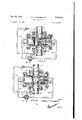
- Fig. 1 is a topplanviewof one embodiment of; my invention shown as interposed in api'pe' line and includingv operating and control means for opening: and' closing the valve.
- Fig. 2 is a. longitudinal view in partial section of; one embodiment of my invention showninEig l and in closed condition; manually operable.
- control means is schematically. shown for operating. the valve to its open or its closed positions; the control: means is shown as,preventing.vv the admis sion of fluid pressure. to the valve to operate the same.
- Fig, 3 is a view similar to.Fig.2. in. partial section except the piston-is shown. ashaving made a.
- the manually operable eon-trolmeans is schematically shown as: admitting fluid pressure to. the valve to. movethe piston: to;- its: fully open position.
- Fig. 4 isza longitudinal, viewin partial section with the pistoninits. full openposition and the: valve fully open; the manually operable and; schematically shown control: means;- is.- shown as: preventing the admission of fluid pressure tosthe valve as the valve. is. fully open.
- Thea-control; means, needs not be: closed butmay beleft open if desired as later explained.
- Figs. 5 and fi are sections taken on the; lines 5" and 6' respectively" of Fig: 2.
- Fig. 9 is a schematic view of the direction con: trol valve 'setfor moving the piston to its closed position;
- valves or the reciprocating piston type are-usedto control-- the new offluicls-such asoils or other fluids which may-containabrasive materials such asgrit orsand that the wear on the piston and valve body may be excessive.
- Thls wear is: foundto at and during the initial opening of the valve.
- This means comprises a butterfly type of valve" rotatable in the port of the piston.
- Wherr'the butterfly valve isslightly open athrottling act-ion occurs within the port of the piston thus'transferring the Wear from the body to the wall or the piston port and edge of the" butterfly valve.
- This wear on thepi'ston-port wall and edgeof the butterfly valve may be greatly reducedand inmany' caseseliminated by inserting a replaceable nam in the piston port and providing the butterfly valvewith-acover, in whole or part, of wear resisting material.
- the preferred embodiment of my invention comprises the body I which may be of any dimensions to meet requirements.
- the body is closed at the ends by the head members 2 and 2', which are secured in place by bolts and nuts.
- the body is provided with a cylindrical bore 3 in which is mounted a reciprocating member or piston provided with a port or through opening 5, preferably round in cross-section, and which registers with the inlet opening 6 and the outlet opening 1, also preferably round in cross-section, in the valve body I.
- Fig. 2 the valve is shown closed and in Fig. 4 the valve is shown as open.
- the said sections may be square.
- the piston 4 is provided with circumferential grooves in which may be placed rubber, leather or metal packing rings or other suitable packing 9. With properly close fit between body I and piston 4 the packing 9 may be omitted and grease grooves alone may be employed as well known in the art.
- the reciprocating piston is prevented from rotating by a dowel I! which is fixed to and projects through the body and into the longitudinal groove ll.
- control valve l2, 1 As I am not claiming the construction of the control valve l2, 1 have shown schematically herein a specified form of control valve which is of the rotary type and is operable manually to the three positions as shown schematically in Figs. 2, 3 and 9.
- the control valve l2 may be placed anywhere convenient, either adjacent to or remote from the valve l and under proper manual operation by the handle 13 to admit fluid pressure to either end of the valve 1 and at the same time exhaust air from the other end of valve l to atmosphere.
- control valve In Fig. 3, the control valve is shown as admitting fluid pressure from the supply pipe 16 to the cylinder, thus moving the piston to its open position.
- Fig. 4 if the control valve D is set as in Fig. 9 and the valve l8 opened, the fluid pressure would be permitted to flow to the other end of the cylinder as shown by dotted lines in the piping and would move the piston to its closed position.
- valve i In connecting valve i into a pipe line, I prefer to install a by-pass pipe l5around valve l conmeeting the main pipes l6 and I1. I introduce into the by-pass pipe two valves 18 and I9 and connect the by-pass pipe to the control valve 12 as shown in Figs. 1 to 4 inclusive.
- valve 1 Should pressure fail entirely on both sides of the main valve I so that operation of valve 1 from either pipe it or ll is impossible, I have provided a pipe and valve 20 at each end of the valve body communicating with the interior of the valve body and by means of which pressure may be introduced into the valve body by means of a hand operated air pressure pump or other convenient means.
- control valve I2 is set for moving the piston and the by-pass valve l8 opened, thereby permitting fluid pressure to flow from the pipe 4 it into the pipe [4 and 2
- This will move the piston from the position shown in Fig. 2 to that shown in Fig. 4 in which the valve is fully open for the flow of fluid pressure from line pipe it into line pipe ll.
- the by-pass valve 18 may be closed and the control valve 12 moved to its neutral position as in Fig. 4.
- control valve 12 will be set as in Fig. 9 and the valve I8 opened thus putting fluid pressure into the right hand end of the cylinder through pipe I4 and 22 and exhausting air from the other end of the cylinder to the atmosphere through pipes 2
- valve H! is opened and the valve 18 closed.
- the normal position of the main valve I is with the longitudinal axis of the piston in a horizontal position.
- fluid pressure I refers to such fluids under pressure as gas, air, water, oil, volatile liquids, etc.
- the pipes I6 and H are shown attached to the valve body by means of flanges 24 but the connection may be made by direct threading or other means.
- An important feature of my invention as previously stated is to provide means to prevent damage to the valve body by the action thereon of the fluids flowing through the valve as the valve starts to open with practically no pressure in the outlet line H, especially when the pressure is high and the fluid carries abrasive particles.
- valve parts may be made of the usual standard materials for such purpose namely, cast iron, cast steel and bronze.
- valve 25 of the butterfly type which is mounted on a shaft 25 to rotate therewith through degrees.
- the operation of the valve 25 is automatic and relative to the longitudinal movement of the piston a.
- valve 25 When the piston is in its closed position the valve 25. is set to close the opening 5 (Fig. 2) and when the piston is in its fuily open position the valve 25 is in its fully open position (Fig. 4)
- the tube 21 is provided with a slot 28 and the shaft 26 is provided with a guide pin 26 secured to the shaft and extending into the slot 28.
- the slot 28 is curved which causes the valve 25 to rotate when the piston reciprocates and the form of the slot determines the rate of movement of the valve 25 relative to the movement of the piston,
- Thelciirvature: of. the .slot may be: such as to start. thevalve 25.; to open.- atz-any .point; during the movement of the piston in its opening-.direce tion.- In .Fig; 3 thepistonzis shown aseaboutonethird: open and the .-butterfly;valve is still closed butta. glance at .theslot 28 :will show. that the slot starts to curve withrespeotto the pin 26, therefore: the :valve .25 will now. begin to rotate .to its openposition. -,This allows the; piston to becwell pastits fcracking":positionebefore the flow of the fluidqpressure .begins.
- plastic.materials-such as' ruhber, etc. are-resilient and the abrasive particles re-. bound from same without-materially affecting it.
- the shaft .-.26 and tubeZ'l may beinterchanged inwhich case-thepin 26 will be stationary andthe. tube and slot will move with the piston,. or other equivalent means to-autcmatically. rotate the valve 25 (01230) maybe used.
- the piston i is so designed withrespec-t to the length ofthe bore. 3 that the;pis ton will contact theend members 2 and-2' to act as stops when the passage 5 is properly positioned with respect to the. ports .6 and-l.
- valve 25.. concealed withinthebody, .a compact device is the result and-.thesaid means -is free from injury but easy of access thereto by removal of head 2.
- valve for a fluid, pressure pipeline comprising a cylinder having: ports in the i side Wall thereof and a piston slidable in saidcylinder'for controlling the ports andadapted to 1 close the ports in one. position of saidpistonandthe iston having means. ion-connecting saidports in another positiontopermittherflow of a fluid therethrough .and means; for. effecting movement of;the saidpistongto the. said twopositions, the combination withv the saidpistonoi automatically controlled means" to. check the flow of fluid through. theports. until the. piston has uncovered the .ports a predetermined: amount. and means to move the said automatically. .controlled means after'the piston hasiuncovered the ports said predetermined amount-to remove said check .to the flow of'fluidszthrough thevalveby the time the piston reachesits fully open position.
- a .valve fora fluid pressurepipe. line comprising a body havinga boreland ports in the sidewalls of the body,-a. reciprocating piston slidable: in :said bore .and' having .means to :close. the ports when in one position and.:having other means to connect the. ports when its other posit-ion,;still other means associatedwiththe piston to maintainsaid zvalve .closed until the. piston has uncovered the ports a predetermined amount andmeanswholly within-said bore to automaticallymovethe lastsaidmeansto efijecta full opening of the: :valve by; the .time the piston reachattid other position,
- valve fora fluid pressure pipe 'line comprisingwa cylinder :having ports in the side Walls thereof,: a piston-slidable in the cylinder and adapted to'close the ports in one position of the piston, .the piston having. .an opening therethrough for connectingtheuports .in another. position of the piston, means positioned in the openingand operable to :twopositions. to control the openingthrough the. piston andmeans to automatically control the movements of the last said means: .as the: piston. moves from .either position to .its other position.
- a pipeline opening and closing valve comprising a, body having a bore provided with an inlet andan. outletopening and means for 'attaching the adjacent ends of the pipe line to the inlet and to the outlet, a reciprocating piston valve in the bore movable across the openings, the piston in one position closing the openings and having a transverse passage adapted to connect the openings when the piston valve is in the other position, control -means associated Withthe piston and positioned within the said passagei-to control theflow of: fluid pressure piston moves back and I through the passage, the control means closing the passage when the piston is in said one position and opening the passage when the piston is in the said other position, means to automatically move the control means from its closed position to its open position at a predetermined rate relative to the rate of movement of the piston and means connected to the ends of the bore whereby fluid under pressure from the pipe line may be applied to the bore to move the piston to either of its positions.
- a pipe line opening and closing valve comprising a body having a bore provided with an inlet and an outlet opening and means for attaching the adjacent ends of the pipe line to the inlet and to the outlet, a reciprocating piston valve in the bore movable across the openings, the piston in one position closing the openings and having a transverse through passage adapted to connect the openings when the piston valve is in the other position, control means associated with the piston and positioned within the said passage to control the flow of fluid pressure through the passage, operating means associated with the control means to automatically efieot a rotational movement thereof as the piston valve moves from one position to its other position and means connected to the ends of the bore whereby fluid under pressure from the pipe line may be applied to the bore to move the piston to either of its positions.
- a pipe line opening and closing valve comprising a body having a bore provided with an inlet and an outlet opening and means for attaching the adjacent ends of the pipe line to the inlet and to the outlet, a reciprocating piston valve in the bore movable across the openings, the piston in one position closing the openings and having a transverse through passage adapted to connect the openings when the piston valve is in the other position, control means associated with the piston and positioned within the said passage to control the flow of fluid pressure through the passage, operating means associated with the control means to automatically effect a rotational movement thereof as the piston valve moves from one position to its other position, the operating means provided with means to effect a predetermined rate of rotation of the control means and means connected to the ends of the bore whereby fluid under pressure from the pipe line may be applied to the bore to move the piston to either of its positions.
- a valve comprising a body having transversely disposed passages, closing means at the ends of one passage and means at each end of the other passage to attach pipes thereto, the said one passage constituting a bore with a nonrotatable longitudinally movable piston valve mounted in the bore and of less length than the bore, a transverse opening through the piston and arranged to fully register with the said other passage only when the piston is at one end of its stroke, the piston being arranged to close the said other passage when the piston is at the other end of its stroke, a rotatable valve positinned in the transverse opening in the piston, elongated means associated with one of the closing means, elongated means associated with the rotatable valve and telescopically associated with the first said elongated means and means on one elongated means cooperating with means on the other elongated means to automatically effect the rotation of the rotatable valve as the piston moves from end to end .of the bore whereby the trans- 8 verse opening will be fully open when the said opening fully
- a valve for a fluid pressure pipe line comprising a cylinder having ports in the side wall thereof, a non-rotatable piston slidable in said cylinder to two positions and adapted to close the ports in one position of the piston, the piston having a passage therethrough for connecting the ports in the other position of the piston, a rotatable auxiliary valve in the said passage to close the passage while the piston is in said one position and to open said passage while the piston is in said other position, means to rotate the valve and fixed means secured to the cylinder within the cylinder and cooperating with the first means to effect a rotation of the auxiliary valve to its open position from its closed position and vice versa.
- a valve according to claim 10 characterized by the said cooperating means being so constructed and related that the movement of the auxiliary valve shall be other than uniform with the movement of the piston.
- a valve for a pipe line comprising a body having a bore provided with inlet and outlet openings, a reciprocating non-rotatable piston valve in the bore movable across the openings, the piston in one position closing the openings and having a transverse passage adapted to connect the openings when the piston is in the other position, a rotatable valve positioned within the passage to open and close the passage and means associated with the rotatable valve, other means associated with the body and cooperating with the first means to move the rotatable valve to its two positions, one of the said means provided with a cam like means to control the rate of rotation of the rotatable means, and means to control the supply of fluid pressure to the ends of said bore to effect movement of the piston to either of its two positions.
- a piston for a reciprocating type of valve body comprising an elongated cylindrical memher having a transverse opening at one end of the member and the other end longitudinally recessed back to the wall of said opening, a butterfly valve positioned in the opening, rotatable means to which the butterfly valve is secured to mount the valve in said opening and to rotate with the rotatable means, the said rotatable means extending through the wall of the said opening and projecting into the said longitudinal recess and means on the rotatable means adapted to cooperate with fixed means within the valve body to effect rotation of the rotatable means whereby the opening in the piston may be automatically opened and closed as the piston moves back and forth in said valve body.
Description
DecQlS, 1949 J. T. LUSIGNAN, JR 2,490,913
PIPE LINE VALVE Filed Nov 30, 1945 3 Sheets-Sheet 1 In 0 e n for JOSEPH Z LZISIG'NHN JR.
Attorney Dec. 13, 1949 J. T. LUSIGNAN, JR
PIPE LINE VALVE 3 Sheets-Sheet 5 Filed Nov. 30, 1945 [n we n for JOSEPH Z ZUSIGNAN JR.
Attorney Patented Dec. 13, 1949 to The Ohio Brass Co J12, Mansfield,"- Ohio, assignor any; Mansfield, Ohio; at-
corporatimizofiNew Jersey Application November 30, 1945; Serial No; 631,877"
1:3 Claims. I
My invention relates; to fluid pressure systems and has special reference to means for control{- ling the flow of fiui'd's through the pipes of the system. My invention is particularly adapted for use in pipeline systems for'transmitting'fiuids under high pressures.
One object of my invention is toprovid'ea valve-of a type in which the piston reciprocates to its open and closed positions to permit or'to check the flow or a-fi-uid; gas or liquid, through the system.
Another object is to prevent or materially reduce the excessive wear on certain parts of'the valve due to the. cutting action of the fluid, especially as the valve begins, to open, under high pressure of the fluid.
Still another object, offmy invention is'to provide auxiliary means associated with; the" reciprocating piston to materially check theqflow of" fluid through the valve during the initial opening of the valve.
Still another object of my invention is to provide means to automatically control the movement of the auxiliary means relative to the longitudinal movements of the reciprocating'pi's'ton.
Other objects of'my-inventionwil'l be disclosed; asthe description, of my invention proceeds.
Fig. 1 is a topplanviewof one embodiment of; my invention shown as interposed in api'pe' line and includingv operating and control means for opening: and' closing the valve.
Fig. 2 is a. longitudinal view in partial section of; one embodiment of my invention showninEig l and in closed condition; manually operable. control means is schematically. shown for operating. the valve to its open or its closed positions; the control: means is shown as,preventing.vv the admis sion of fluid pressure. to the valve to operate the same.
Fig, 3 is a view similar to.Fig...2. in. partial section except the piston-is shown. ashaving made a.
partial, opening but. the valve'is. still closed. as,
later explained; the manually operable eon-trolmeans is schematically shown as: admitting fluid pressure to. the valve to. movethe piston: to;- its: fully open position.
Fig... 4 isza longitudinal, viewin partial section with the pistoninits. full openposition and the: valve fully open; the manually operable and; schematically shown control: means;- is.- shown as: preventing the admission of fluid pressure tosthe valve as the valve. is. fully open. Thea-control; means, needs not be: closed butmay beleft open if desired as later explained.
2. Figs. 5 and fi are sections taken on the; lines 5" and 6' respectively" of Fig: 2.
7 and 8 are sections taken on thelines- 1- and 'respectively'of' Fig: 4.
Fig. 9 is a schematic view of the direction con: trol valve 'setfor moving the piston to its closed position;
Fig.- 10" of the piston and auxiliary valve as later ex-'- plained;
Experience has shown" that when valves or the reciprocating piston type are-usedto control-- the new offluicls-such asoils or other fluids which may-containabrasive materials such asgrit orsand that the wear on the piston and valve body may be excessive.
This: is particularly true when there is no pres sure' or practically none on theou-tlet side ofthe valve;- as the piston is moved' to its open position.
This wear is greatest on thevalve body over an areaadjacent the point a: (Fig: 3') ontheoutlet side of the valve and the result of the high velocity of thefluidand-the impact of the abra-- sive'" particles against such area.-
Thls wear is: foundto at and during the initial opening of the valve.
Afterthe piston has moved to a position vvhere' the valveis' substantially" open orpressure builds up'ln the outlet'side of the valve this'-wearis greatly reduced or practically nil.
As pointed outthis-wear is particularlysevere onthe bodyporticnof thevalvetowhich the pipe line is-attached therefore I provide means which protectthe body" portionfrom thiswear, and any wear whichthen takes place is in connection with the piston which is much more easily and* economically replaced or repaired.
This means comprises a butterfly type of valve" rotatable in the port of the piston. Wherr'the butterfly valve isslightly open athrottling act-ion occurs within the port of the piston thus'transferring the Wear from the body to the wall or the piston port and edge of the" butterfly valve. When the fluidsa-refree of abrasive particles this wear is 'quiteinconsequentia-P for a long period" of time:
This wear on thepi'ston-port wall and edgeof the butterfly valve may be greatly reducedand inmany' caseseliminated by inserting a replaceable nam in the piston port and providing the butterfly valvewith-acover, in whole or part, of wear resisting material.
l fthe opening of the butterfly'valve is delayed. for'a' time to permit apartial' opening offthe pistom-port thewear upon the body will be substane isa sectional view of a modificationtake place prii-icipal1y 3 tially eliminated, therefore I provide means to automatically open the butterfly valve after the piston has moved to its open position a predetermined amount.
The preferred embodiment of my invention comprises the body I which may be of any dimensions to meet requirements. The body is closed at the ends by the head members 2 and 2', which are secured in place by bolts and nuts. The body is provided with a cylindrical bore 3 in which is mounted a reciprocating member or piston provided with a port or through opening 5, preferably round in cross-section, and which registers with the inlet opening 6 and the outlet opening 1, also preferably round in cross-section, in the valve body I. In Fig. 2, the valve is shown closed and in Fig. 4 the valve is shown as open. The said sections may be square.
The piston 4 is provided with circumferential grooves in which may be placed rubber, leather or metal packing rings or other suitable packing 9. With properly close fit between body I and piston 4 the packing 9 may be omitted and grease grooves alone may be employed as well known in the art.
The reciprocating piston is prevented from rotating by a dowel I!) which is fixed to and projects through the body and into the longitudinal groove ll.
As I am not claiming the construction of the control valve l2, 1 have shown schematically herein a specified form of control valve which is of the rotary type and is operable manually to the three positions as shown schematically in Figs. 2, 3 and 9.
The control valve l2 may be placed anywhere convenient, either adjacent to or remote from the valve l and under proper manual operation by the handle 13 to admit fluid pressure to either end of the valve 1 and at the same time exhaust air from the other end of valve l to atmosphere.
In Fig. 3, the control valve is shown as admitting fluid pressure from the supply pipe 16 to the cylinder, thus moving the piston to its open position. In Fig. 4, if the control valve D is set as in Fig. 9 and the valve l8 opened, the fluid pressure would be permitted to flow to the other end of the cylinder as shown by dotted lines in the piping and would move the piston to its closed position.
In connecting valve i into a pipe line, I prefer to install a by-pass pipe l5around valve l conmeeting the main pipes l6 and I1. I introduce into the by-pass pipe two valves 18 and I9 and connect the by-pass pipe to the control valve 12 as shown in Figs. 1 to 4 inclusive. By this arrangement I am able to utilize fluid pressure from either pipe H5 or II by proper manipulation of the valves [B or [9.
Should pressure fail entirely on both sides of the main valve I so that operation of valve 1 from either pipe it or ll is impossible, I have provided a pipe and valve 20 at each end of the valve body communicating with the interior of the valve body and by means of which pressure may be introduced into the valve body by means of a hand operated air pressure pump or other convenient means.
In the arrangement shown. in Fig. 2 the piston is in extreme closed position and the valve closed and the by-pass valves closed and the control valve is in its neutral position.
In Fig. 3 the control valve I2 is set for moving the piston and the by-pass valve l8 opened, thereby permitting fluid pressure to flow from the pipe 4 it into the pipe [4 and 2| to one end of the cylinder as shown by the arrows, and the air in the other end of the cylinder will flow through the pipes 22 and 23 to atmosphere as shown by the arrows. This will move the piston from the position shown in Fig. 2 to that shown in Fig. 4 in which the valve is fully open for the flow of fluid pressure from line pipe it into line pipe ll. In this position the by-pass valve 18 may be closed and the control valve 12 moved to its neutral position as in Fig. 4.
If it is now desired to close the main valve, the control valve 12 will be set as in Fig. 9 and the valve I8 opened thus putting fluid pressure into the right hand end of the cylinder through pipe I4 and 22 and exhausting air from the other end of the cylinder to the atmosphere through pipes 2| and 23 to move the piston to its closed position after which the by-pass and control valves may be set as in Fig. 2.
If desired to operate the valve 1' by means of fluid pressure from line pipe ll, then the valve H! is opened and the valve 18 closed.
The normal position of the main valve I is with the longitudinal axis of the piston in a horizontal position.
By fluid pressure I refer to such fluids under pressure as gas, air, water, oil, volatile liquids, etc.
The pipes I6 and H are shown attached to the valve body by means of flanges 24 but the connection may be made by direct threading or other means.
An important feature of my invention as previously stated is to provide means to prevent damage to the valve body by the action thereon of the fluids flowing through the valve as the valve starts to open with practically no pressure in the outlet line H, especially when the pressure is high and the fluid carries abrasive particles.
If the fluids are free of abrasives, the valve parts may be made of the usual standard materials for such purpose namely, cast iron, cast steel and bronze.
To overcome the undesirable wear on the body I referred to above I provide in the opening 5 of the piston, means to prevent or substantially check the flow until the piston has moved a predetermined distance toward its fully open position.
To accomplish this improvement I introduce into the opening 5 a valve 25 of the butterfly type which is mounted on a shaft 25 to rotate therewith through degrees. The operation of the valve 25 is automatic and relative to the longitudinal movement of the piston a.
When the piston is in its closed position the valve 25. is set to close the opening 5 (Fig. 2) and when the piston is in its fuily open position the valve 25 is in its fully open position (Fig. 4)
To effect movement of the butterfly valve 25 relative to the movement of the piston l, there is secured to the head 2 a tube-like member 2'! as by welding, threading or otherwise. The shaft 25 is telescopically mounted in the tube 21' to move relative thereto with the movement of the piston.
The tube 21 is provided with a slot 28 and the shaft 26 is provided with a guide pin 26 secured to the shaft and extending into the slot 28. The slot 28 is curved which causes the valve 25 to rotate when the piston reciprocates and the form of the slot determines the rate of movement of the valve 25 relative to the movement of the piston,
Thelciirvature: of. the .slot: may be: such as to start. thevalve 25.; to open.- atz-any .point; during the movement of the piston in its opening-.direce tion.- In .Fig; 3 thepistonzis shown aseaboutonethird: open and the .-butterfly;valve is still closed butta. glance at .theslot 28 :will show. that the slot starts to curve withrespeotto the pin 26, therefore: the :valve .25 will now. begin to rotate .to its openposition. -,This allows the; piston to becwell pastits fcracking":positionebefore the flow of the fluidqpressure .begins.
As the valve- 25- begins::t open,-.and=.thesfiuid under-pressure begins to flow,any. cutting;.or abrasive-actionwill; takesplace intrher walliof :;the opening at the rim-oftthezivalve;25.and alsoon the.- .edge-. of:the valve-'25.: :-..However thisrmay-be almost if not entirely overcome bynplacing, a re.-. newablelining 29 (Fig-:1 0). 11in; the piston: for the opening 5 made of a wear resisting materialsuch as:-;white or .hardroast ironsorrsome chrome alloy of .steel and: by making the. waive-.30 of :the. same material.
If the wear..ontheriliningi29izor.the valve3il (Fig. when madeoofewear resistingimaterial should become. .excessive zthey1 are: .quite. easily replacedcompared: to .that ;of replacing the. entire valve or bodymembers.
This .29.- could: beamade. of:.=natura1.-.or synthetic rubber .;orl other-plastic not afiected by the flowing .material :and the uv-alve 25 :could :have a covering-of the:.same;material.
The construction; zandematerial .used... in. .the valve .should be .chosen with regard." to the fluid.- to .be controlled and; theramount and nature. of abrasive materials it maycarry.
Many of the plastic.materials-such as' ruhber, etc. are-resilient and the abrasive particles re-. bound from same without-materially affecting it.
White .orhard. cast, iron; chromium alloysteels, etc. resist 'wear due to their great'hardnessh For use with fluids freeifromabrasive particles, valves of ordinary cast.:.iron, -cast steel, bronze. etc. will be entirely satisfactory-when.provided with the cam-like means. to effiect proper movement of the butterfly :valve relative to that of the piston.
If .desired the shaft .-.26 and tubeZ'l may beinterchanged inwhich case-thepin 26 will be stationary andthe. tube and slot will move with the piston,. or other equivalent means to-autcmatically. rotate the valve 25 (01230) maybe used.
The piston i is so designed withrespec-t to the length ofthe bore. 3 that the;pis ton will contact theend members 2 and-2' to act as stops when the passage 5 is properly positioned with respect to the. ports .6 and-l.
Having the means to automaticallymotate the.
Modifications; will suggest themselves to those skilled. in the art from the disclosure vI have herein made; and, therefore, I wish tobe limited only by my claims.
I claimz- 1. Inza valve for fluid pressures comprising-a cylinder having ports in the side wall thereof and a pistonslidable in said cylinderand adaptedto close said ports in one position .ofsaid piston-and the: piston. having .an openingztherethrough. for connecting .said ports in. another-:apositiomof said piston and means ionefiecting:morementrofisaid piston. to its;dawo.positions,...the:combination-with said piston ;of an; auxiliary valve: positioned in said; opening: to maintainasaid.aopeninglclosed untilthe piston hasmoveda predetermined dis.- tanoeztoward its fully open position: and means automatically effecting movement. of said auxiliaryvalve to its open; position as the piston moves beyond the said predetermined position and until it reaches its fully. open position.
2. Inc. valve for a fluid, pressure pipeline, comprising a cylinder having: ports in the i side Wall thereof and a piston slidable in saidcylinder'for controlling the ports andadapted to 1 close the ports in one. position of saidpistonandthe iston having means. ion-connecting saidports in another positiontopermittherflow of a fluid therethrough .and means; for. effecting movement of;the saidpistongto the. said twopositions, the combination withv the saidpistonoi automatically controlled means" to. check the flow of fluid through. theports. until the. piston has uncovered the .ports a predetermined: amount. and means to move the said automatically. .controlled means after'the piston hasiuncovered the ports said predetermined amount-to remove said check .to the flow of'fluidszthrough thevalveby the time the piston reachesits fully open position.
3. A .valve fora fluid pressurepipe. line comprising a body havinga boreland ports in the sidewalls of the body,-a. reciprocating piston slidable: in :said bore .and' having .means to :close. the ports when in one position and.:having other means to connect the. ports when its other posit-ion,;still other means associatedwiththe piston to maintainsaid zvalve .closed until the. piston has uncovered the ports a predetermined amount andmeanswholly within-said bore to automaticallymovethe lastsaidmeansto efijecta full opening of the: :valve by; the .time the piston reachessaid other position,
, 4. 'A valve fora fluid pressure pipe 'line comprisingwa cylinder :having ports in the side Walls thereof,: a piston-slidable in the cylinder and adapted to'close the ports in one position of the piston, .the piston having. .an opening therethrough for connectingtheuports .in another. position of the piston, means positioned in the openingand operable to :twopositions. to control the openingthrough the. piston andmeans to automatically control the movements of the last said means: .as the: piston. moves from .either position to .its other position.
5. :A valve for-.a fluid pressure pipe line com-- prising a cylinder having ports in the side wall thereof, a piston slidably mounted in the cylinder and provided with anopening therethrough for controlling the opening and closing of the ports and means mounted in the opening and movable with the piston for controlling-the opening andclosing of the opening through the pistonand other .means .to automatically operate the first means in synchronism with the movements of its pistonas the forth in the cylinder.
6. A pipeline opening and closing valve comprising a, body having a bore provided with an inlet andan. outletopening and means for 'attaching the adjacent ends of the pipe line to the inlet and to the outlet, a reciprocating piston valve in the bore movable across the openings, the piston in one position closing the openings and having a transverse passage adapted to connect the openings when the piston valve is in the other position, control -means associated Withthe piston and positioned within the said passagei-to control theflow of: fluid pressure piston moves back and I through the passage, the control means closing the passage when the piston is in said one position and opening the passage when the piston is in the said other position, means to automatically move the control means from its closed position to its open position at a predetermined rate relative to the rate of movement of the piston and means connected to the ends of the bore whereby fluid under pressure from the pipe line may be applied to the bore to move the piston to either of its positions.
'7. A pipe line opening and closing valve comprising a body having a bore provided with an inlet and an outlet opening and means for attaching the adjacent ends of the pipe line to the inlet and to the outlet, a reciprocating piston valve in the bore movable across the openings, the piston in one position closing the openings and having a transverse through passage adapted to connect the openings when the piston valve is in the other position, control means associated with the piston and positioned within the said passage to control the flow of fluid pressure through the passage, operating means associated with the control means to automatically efieot a rotational movement thereof as the piston valve moves from one position to its other position and means connected to the ends of the bore whereby fluid under pressure from the pipe line may be applied to the bore to move the piston to either of its positions.
8. A pipe line opening and closing valve comprising a body having a bore provided with an inlet and an outlet opening and means for attaching the adjacent ends of the pipe line to the inlet and to the outlet, a reciprocating piston valve in the bore movable across the openings, the piston in one position closing the openings and having a transverse through passage adapted to connect the openings when the piston valve is in the other position, control means associated with the piston and positioned within the said passage to control the flow of fluid pressure through the passage, operating means associated with the control means to automatically effect a rotational movement thereof as the piston valve moves from one position to its other position, the operating means provided with means to effect a predetermined rate of rotation of the control means and means connected to the ends of the bore whereby fluid under pressure from the pipe line may be applied to the bore to move the piston to either of its positions.
9. A valve comprising a body having transversely disposed passages, closing means at the ends of one passage and means at each end of the other passage to attach pipes thereto, the said one passage constituting a bore with a nonrotatable longitudinally movable piston valve mounted in the bore and of less length than the bore, a transverse opening through the piston and arranged to fully register with the said other passage only when the piston is at one end of its stroke, the piston being arranged to close the said other passage when the piston is at the other end of its stroke, a rotatable valve positinned in the transverse opening in the piston, elongated means associated with one of the closing means, elongated means associated with the rotatable valve and telescopically associated with the first said elongated means and means on one elongated means cooperating with means on the other elongated means to automatically effect the rotation of the rotatable valve as the piston moves from end to end .of the bore whereby the trans- 8 verse opening will be fully open when the said opening fully registers with the aforesaid other passage.
10. A valve for a fluid pressure pipe line comprising a cylinder having ports in the side wall thereof, a non-rotatable piston slidable in said cylinder to two positions and adapted to close the ports in one position of the piston, the piston having a passage therethrough for connecting the ports in the other position of the piston, a rotatable auxiliary valve in the said passage to close the passage while the piston is in said one position and to open said passage while the piston is in said other position, means to rotate the valve and fixed means secured to the cylinder within the cylinder and cooperating with the first means to effect a rotation of the auxiliary valve to its open position from its closed position and vice versa.
11. A valve according to claim 10 characterized by the said cooperating means being so constructed and related that the movement of the auxiliary valve shall be other than uniform with the movement of the piston.
12. A valve for a pipe line comprising a body having a bore provided with inlet and outlet openings, a reciprocating non-rotatable piston valve in the bore movable across the openings, the piston in one position closing the openings and having a transverse passage adapted to connect the openings when the piston is in the other position, a rotatable valve positioned within the passage to open and close the passage and means associated with the rotatable valve, other means associated with the body and cooperating with the first means to move the rotatable valve to its two positions, one of the said means provided with a cam like means to control the rate of rotation of the rotatable means, and means to control the supply of fluid pressure to the ends of said bore to effect movement of the piston to either of its two positions.
13. A piston for a reciprocating type of valve body comprising an elongated cylindrical memher having a transverse opening at one end of the member and the other end longitudinally recessed back to the wall of said opening, a butterfly valve positioned in the opening, rotatable means to which the butterfly valve is secured to mount the valve in said opening and to rotate with the rotatable means, the said rotatable means extending through the wall of the said opening and projecting into the said longitudinal recess and means on the rotatable means adapted to cooperate with fixed means within the valve body to effect rotation of the rotatable means whereby the opening in the piston may be automatically opened and closed as the piston moves back and forth in said valve body.
JOSEPH T. LUSIGNAN, JR.
REFERENCES CITED The following references are of record in the file of this patent:
UNITED STATES PATENTS Number Name Date 623,873 Borden Apr. 25, 1899 904,852 Dwyer Nov. 24, 1908 1,193,780 Hoag- Aug. 8, 1916 1,251,453 Spencer Dec. 25, 1917 1,780,160 Leach Nov. 4, 1930 2,059,687 Gagg Nov. 3, 1936 2,337,841 Shafer Dec. 28, 1943.
Priority Applications (1)
| Application Number | Priority Date | Filing Date | Title |
|---|---|---|---|
| US631877A US2490913A (en) | 1945-11-30 | 1945-11-30 | Pipe-line valve |
Applications Claiming Priority (1)
| Application Number | Priority Date | Filing Date | Title |
|---|---|---|---|
| US631877A US2490913A (en) | 1945-11-30 | 1945-11-30 | Pipe-line valve |
Publications (1)
| Publication Number | Publication Date |
|---|---|
| US2490913A true US2490913A (en) | 1949-12-13 |
Family
ID=24533146
Family Applications (1)
| Application Number | Title | Priority Date | Filing Date |
|---|---|---|---|
| US631877A Expired - Lifetime US2490913A (en) | 1945-11-30 | 1945-11-30 | Pipe-line valve |
Country Status (1)
| Country | Link |
|---|---|
| US (1) | US2490913A (en) |
Cited By (2)
| Publication number | Priority date | Publication date | Assignee | Title |
|---|---|---|---|---|
| US2951340A (en) * | 1956-01-03 | 1960-09-06 | Curtiss Wright Corp | Gas turbine with control mechanism for turbine cooling air |
| FR3010087A1 (en) * | 2013-09-03 | 2015-03-06 | Solvay | PROCESS FOR DISSOLVING (FRAGMENTS OF) ARTICLES OF PLASTIC MATERIAL |
Citations (7)
| Publication number | Priority date | Publication date | Assignee | Title |
|---|---|---|---|---|
| US623873A (en) * | 1899-04-25 | Damper | ||
| US904852A (en) * | 1908-07-07 | 1908-11-24 | Thomas E Dwyer | Stop-cock. |
| US1193780A (en) * | 1916-08-08 | Steam-valve | ||
| US1251453A (en) * | 1915-09-18 | 1917-12-25 | Organ Power Company | Valve. |
| US1780160A (en) * | 1928-01-21 | 1930-11-04 | Leach Robert William | Valve |
| US2059687A (en) * | 1935-01-29 | 1936-11-03 | Wright Aeronautical Corp | Deicing throttle |
| US2337841A (en) * | 1942-07-14 | 1943-12-28 | Ohio Brass Co | Control valve |
-
1945
- 1945-11-30 US US631877A patent/US2490913A/en not_active Expired - Lifetime
Patent Citations (7)
| Publication number | Priority date | Publication date | Assignee | Title |
|---|---|---|---|---|
| US623873A (en) * | 1899-04-25 | Damper | ||
| US1193780A (en) * | 1916-08-08 | Steam-valve | ||
| US904852A (en) * | 1908-07-07 | 1908-11-24 | Thomas E Dwyer | Stop-cock. |
| US1251453A (en) * | 1915-09-18 | 1917-12-25 | Organ Power Company | Valve. |
| US1780160A (en) * | 1928-01-21 | 1930-11-04 | Leach Robert William | Valve |
| US2059687A (en) * | 1935-01-29 | 1936-11-03 | Wright Aeronautical Corp | Deicing throttle |
| US2337841A (en) * | 1942-07-14 | 1943-12-28 | Ohio Brass Co | Control valve |
Cited By (2)
| Publication number | Priority date | Publication date | Assignee | Title |
|---|---|---|---|---|
| US2951340A (en) * | 1956-01-03 | 1960-09-06 | Curtiss Wright Corp | Gas turbine with control mechanism for turbine cooling air |
| FR3010087A1 (en) * | 2013-09-03 | 2015-03-06 | Solvay | PROCESS FOR DISSOLVING (FRAGMENTS OF) ARTICLES OF PLASTIC MATERIAL |
Similar Documents
| Publication | Publication Date | Title |
|---|---|---|
| US2974646A (en) | Rotary actuator | |
| US3557822A (en) | Gate valve | |
| US2830784A (en) | General purpose flow valve with alternative fluid pressure or manual control | |
| US4458879A (en) | Valve | |
| US2585556A (en) | Reciprocating valve | |
| US2738803A (en) | Valve | |
| US1643753A (en) | Butterfly valve | |
| US2490913A (en) | Pipe-line valve | |
| US1483991A (en) | Valve | |
| US430089A (en) | sewall | |
| RU181161U1 (en) | Axial Flow Control Valve | |
| US3078069A (en) | Valves | |
| US5899438A (en) | Gate valve having a swingable-slidable valve plate | |
| US3060957A (en) | Valve | |
| US1128228A (en) | Hydraulic valve. | |
| US585377A (en) | Means for operating valves | |
| US1998080A (en) | Valve mechanism | |
| US2272033A (en) | Motor | |
| US1436412A (en) | Valve device | |
| US2961003A (en) | Single-acting piston pump and valve unit | |
| GB2104962A (en) | Hydropneumatic conveyor | |
| US1361581A (en) | Valve | |
| US2975800A (en) | Internal-cylinder-operated valve | |
| US2991794A (en) | Valve for fluids having entrained solids | |
| US2592352A (en) | Valve |