US2490389A - Quick action fuse - Google Patents
Quick action fuse Download PDFInfo
- Publication number
- US2490389A US2490389A US707173A US70717346A US2490389A US 2490389 A US2490389 A US 2490389A US 707173 A US707173 A US 707173A US 70717346 A US70717346 A US 70717346A US 2490389 A US2490389 A US 2490389A
- Authority
- US
- United States
- Prior art keywords
- lever
- pin
- fuze
- slider
- projectile
- Prior art date
- Legal status (The legal status is an assumption and is not a legal conclusion. Google has not performed a legal analysis and makes no representation as to the accuracy of the status listed.)
- Expired - Lifetime
Links
- 238000010304 firing Methods 0.000 description 16
- 238000009987 spinning Methods 0.000 description 5
- 230000001133 acceleration Effects 0.000 description 4
- 238000005474 detonation Methods 0.000 description 4
- 229910000760 Hardened steel Inorganic materials 0.000 description 2
- 235000015842 Hesperis Nutrition 0.000 description 2
- 235000012633 Iberis amara Nutrition 0.000 description 2
- 238000004880 explosion Methods 0.000 description 2
- 239000002360 explosive Substances 0.000 description 2
- 230000000717 retained effect Effects 0.000 description 2
- 101100166842 Arabidopsis thaliana CESA2 gene Proteins 0.000 description 1
- RYGMFSIKBFXOCR-UHFFFAOYSA-N Copper Chemical compound [Cu] RYGMFSIKBFXOCR-UHFFFAOYSA-N 0.000 description 1
- 230000006835 compression Effects 0.000 description 1
- 238000007906 compression Methods 0.000 description 1
- 229910052802 copper Inorganic materials 0.000 description 1
- 239000010949 copper Substances 0.000 description 1
- 229910001385 heavy metal Inorganic materials 0.000 description 1
- 230000002028 premature Effects 0.000 description 1
Images
Classifications
-
- F—MECHANICAL ENGINEERING; LIGHTING; HEATING; WEAPONS; BLASTING
- F42—AMMUNITION; BLASTING
- F42C—AMMUNITION FUZES; ARMING OR SAFETY MEANS THEREFOR
- F42C1/00—Impact fuzes, i.e. fuzes actuated only by ammunition impact
- F42C1/02—Impact fuzes, i.e. fuzes actuated only by ammunition impact with firing-pin structurally combined with fuze
- F42C1/04—Impact fuzes, i.e. fuzes actuated only by ammunition impact with firing-pin structurally combined with fuze operating by inertia of members on impact
- F42C1/06—Impact fuzes, i.e. fuzes actuated only by ammunition impact with firing-pin structurally combined with fuze operating by inertia of members on impact for any direction of impact
Definitions
- This invention relates to projectile fuzes of the inertia type, and more especially to those known as quick-action contact fuzes.
- the invention comprises an inertial mass consisting of a heavy slug arranged to move a very small distance when submitted to deceleration and a lever arm interconnecting the Slug and a firing pin, such that the force derived from the moving slug causes the firing pin to move toward the detonator with much greater velocity than that with which the slug is caused to move by inertia.
- the simple and reliable mechanism provided by the present invention permits the fuze to be located in the base of the projectile so that the charge and ogive can be designed solely on ballistic principles, while providing ultra-rapid fuze action upon impact.
- Fig. 1 is a longitudinal sectional view of a preferred embodiment of a fuze comprising the invention
- Fig. 2 is a transverse cross-sectional view taken along the line 2-2 of the iuze structure of Fig. 1;
- Fig. 3 is a transverse cross-sectional view taken along the line 3-3 of Fig. 1;
- Fig. 4 is a transverse cross-sectional view taken along line 4-4 of Fig. 1;
- Fig. 5 is a transverse cross-sectional view of the fuze chassis plug alone, taken along the line 5-5 of Fig. 1, looking in the direction of the arrows.
- a fuze body I is shown to be threaded in a shell 2
- the explosive charge 24 which would usually fill most of the space between shell 2
- An inertial mass in this case, slug 2 of any suitable heavy metal, is positioned in the shell base, as shown in Fig. 1, in a cavity 3! by means of linear ball bearings 3.
- ball bearings Four such bearings, distributed at intervals around the slug, as shown in Fig. 4, should ordinarily be suificient, although more may be employed.
- the balls are retained in races or grooves formed on the inside surface of the cavity 3
- a stud I which may be of hardened steel, is screwed into a hole threaded to receive it. This stud transmits the movement of slug 2 to a lever I5 positioned directly above it.
- a fuze chassis plug 6 is retained by means of a booster cup I I which is screwed down on top of the chassis plug, as illustrated.
- This chassis plug 6 contains the slider 9, detonator I 0, firing pin 21, firing pin lever I5, and other components providing several safety features later 'to be described.
- the lever I5 which may be of hardened steel, for example, is conveniently formed with an upturned firing pin 21 at its extreme end.
- the firing pin may, however, be formed separately from the lever, provided the pin is suitably actuated by movement of the lever.
- lhe ratio of the distance between the firing pin 2'! and the center of shaft 20 and the distance between the axis of stud 4 and the center of shaft 20 constitutes the mechanical advantage of the lever arm 15.
- This mechanical advantage will necessarily differ in different specific designs of projectiles, but, as an example, I have found that a lever ratio of the order of at least 10 to 1 is desirable to provide sufficiently rapid detonation for shaped charge rockets, although tests with a 5 to 1 ratio gave results superior to any conventional inertia base fuze.
- I subj ected to sufficient cen trifugal ;frce andgsufilcient 1set-backforce.
- 105453 of; a .rifle' shell simultaneous existence of-both of these ;forcescan occur before the shell leavestherifle-barrel from which it isdischarged.
- a centrifugal spring [4 normally-.maintains the slider t in the illustratedazposition at which point detonator. hole 25 therein is out of alignmentwith firing pin hole 22: and lead hole l3'inthe plug 6. Furthermore, it, isilocked in this position by setback pin ll'which extends from plug G'into hole 291insliderrll. Set-back pin Il'is held in this locked'positionbycompression spring l8, which is held'in place by screw I95 It will be seen that when slider 9 is in-the safety position, as
- detonator Ill cannot be detonated even if firing pin 2'l'is actuated.
- slider 9*movesto'the right against spring i i hole25' comes -intoalignment with hole- 22 so that actuation offiring 'pin 21 will detonate detonator IUi During the initial moments'of firing of a shell ora spinning rocketthe set back force due to acceleration is very great.
- a hole 8 is drilled through the center of plug 9 of such size as to receive a .suitable cotter-ipin 3t which is inserted at the time the -fuze isassembled.
- This cotter pin prevents movement of slider 9 and is left in place until the occasion when the fuze is screwed into the base of the shell, rocket, or other projectile.
- This cotter pin 30 is shown in placegin Fig. 5 whichis a view of the chassis plug before it is assembled in the fuze body.
- detonator hole 25 falls into alignment with firing pin hole-22, and lead. hold i3, and-this alignment is maintained until the instant of impact.
- lever arm i5 will in, the same time move forward a considerably greater distance, than. the .stud 4.. 'If-the -mechanical advantage of. the lever is, for
- the;velocity of the firingpin will be 190. times greater than that ,ofr'studfis This velocity ismore than sufiicientto detonate thedetonator i ll when it is struck by. the. firing pin. Z'l'.
- booster cavit l2 contained in the; booster cavit l2, and the resultingexplosion of booster charge fifilwilldetonate.
- An inertia fuze for projectiles comprising a,
Landscapes
- Engineering & Computer Science (AREA)
- General Engineering & Computer Science (AREA)
- Air Bags (AREA)
Description
Dec. 6, 1949 WALES, JR 2,490,389
QUICK ACTION FUSE Filed Nov. 1, 1946 2 Sheets-Sheet 1 ATTORN EYS Dec. 6, 1949 A JR 2,490,389
Filed NOV. 1, 1946 2 Sheets-Sheet 2 NNNNNN OR A/ATHA/V/EL 8. 1446156, Jr. A BY PM W Yam/ 4 0:!
ATTORNEYS Patented Dec. 6, 1949 UNITED STATES PATENT QFFHQ QUICK ACTION FUSE Application November 1, 1946, Serial No. 707,173
-. 1 Claim.
This invention relates to projectile fuzes of the inertia type, and more especially to those known as quick-action contact fuzes.
The iuze in accordance with this invention, while entirely safe previous to discharge of the projectile, is extremely sensitive to small deceleration, and is so rapid in its action that detonation may be caused to occur within about 200 microseconds of the initial impact. Briefiy, the invention comprises an inertial mass consisting of a heavy slug arranged to move a very small distance when submitted to deceleration and a lever arm interconnecting the Slug and a firing pin, such that the force derived from the moving slug causes the firing pin to move toward the detonator with much greater velocity than that with which the slug is caused to move by inertia.
It is well known that there is a critical velocity with which all pyrotechnic detonators must be struck in order to be detonated. One of the difiiculties heretofore encountered in detonating shells and rockets, especially of the shaped charge type, has been to achieve detonation early enough to produce the most effective explosive force at the instant of impact of the projectile. This difiiculty has resulted from the fact that a nose iuze is impracticable because it either is destroyed before it operates properly or else interferes with the effectiveness of the shaped charge, and from the fact that base fuzes of the inertia type previously proposed required an excessively long ogive in order to permit the firing pin to reach the critical detonating velocity at the instant of maximum efiectiveness of the explosion. As above indicated, the simple and reliable mechanism provided by the present invention permits the fuze to be located in the base of the projectile so that the charge and ogive can be designed solely on ballistic principles, while providing ultra-rapid fuze action upon impact.
The nature of this invention will be clearly understood from the following description considered with the drawings, in which:
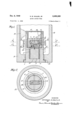
Fig. 1 is a longitudinal sectional view of a preferred embodiment of a fuze comprising the invention;
Fig. 2 is a transverse cross-sectional view taken along the line 2-2 of the iuze structure of Fig. 1;
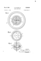
Fig. 3 is a transverse cross-sectional view taken along the line 3-3 of Fig. 1;
Fig. 4 is a transverse cross-sectional view taken along line 4-4 of Fig. 1; and
Fig. 5 is a transverse cross-sectional view of the fuze chassis plug alone, taken along the line 5-5 of Fig. 1, looking in the direction of the arrows.
In Figure 1, a fuze body I is shown to be threaded in a shell 2| which may be assumed to form part of either an artillery shell or a spinning rocket. To make the joint tight it is customary to employ a gasket 23 of lead or copper between these'two members. The explosive charge 24 which would usually fill most of the space between shell 2| and fuze body I would preferably comprise a so-called shaped charge, although the type of charge employed has no necessary relation to the present invention.
An inertial mass, in this case, slug 2 of any suitable heavy metal, is positioned in the shell base, as shown in Fig. 1, in a cavity 3! by means of linear ball bearings 3. Four such bearings, distributed at intervals around the slug, as shown in Fig. 4, should ordinarily be suificient, although more may be employed. The balls are retained in races or grooves formed on the inside surface of the cavity 3|. The purpose of these ball bearings is to reduce the friction between slug 2 and the Walls of cavity 3I in the event that the projectile strikes its target a glancing blow, viz., in an oiT-axis direction. In this event it is important that as much inertial energy as possible be available to provide a force in the direction of the longitudinal axis of the fuze. At the upper end of slug 2 a stud I, which may be of hardened steel, is screwed into a hole threaded to receive it. This stud transmits the movement of slug 2 to a lever I5 positioned directly above it.
In the larger cavity located above the inertia plug 2 a fuze chassis plug 6 is retained by means of a booster cup I I which is screwed down on top of the chassis plug, as illustrated. This chassis plug 6 contains the slider 9, detonator I 0, firing pin 21, firing pin lever I5, and other components providing several safety features later 'to be described.
The lever I5 which may be of hardened steel, for example, is conveniently formed with an upturned firing pin 21 at its extreme end. The firing pin may, however, be formed separately from the lever, provided the pin is suitably actuated by movement of the lever. lhe ratio of the distance between the firing pin 2'! and the center of shaft 20 and the distance between the axis of stud 4 and the center of shaft 20 constitutes the mechanical advantage of the lever arm 15. This mechanical advantage will necessarily differ in different specific designs of projectiles, but, as an example, I have found that a lever ratio of the order of at least 10 to 1 is desirable to provide sufficiently rapid detonation for shaped charge rockets, although tests with a 5 to 1 ratio gave results superior to any conventional inertia base fuze. From the well known fact that the velocity is a function of the square root of the acceleration it follows that if the mechanical advantage of the lever arm I5 is 5 to 1, the velocity of the pin It will be the square root of five times the acceleration of the mass 2, for example. Above lever It a small compression spring I6, known as a creep spring, is positioned normally to press down on the lever so as to hold the firinggpin 46 ,away from detonator Id until the-.-intended:. moment of operation. Especially in the case of projectiles fired from a gun there is a moment of temporary deceleration which, without such a device as spring |E,,.might be sufiicient to permit premature detonation.
In the mentioned example, SljlQhjflfiCQlBfdtiDIl, 06-.- curs at the moment the shell emerges from; the.
muzzle tally in chassis plug 6 incorporates certain conventional safety features. such that the fuze cannot be detonated unless it isrsimultaneously= I subj ected; to sufficient cen trifugal ;frce andgsufilcient 1set-backforce. In the 105453; of; a .rifle' shell simultaneous existence of-both of these ;forcescan occur before the shell leavestherifle-barrel from which it isdischarged.
' In 1 the. case of :a; rocket the zprojectile. would of necessitybegohthespinning type; and the simultaneous existencegof the two, necessaryforces would probably not-.occurauntil a reasonable distancegfromthelpoint; of discharge or-launching of: the rocket-7, 117218,; to, beenoted that although the disclosed safety features; are designed for spinningi'proj ectiles,-.it 1' is evident that my lever action principle isninzno: wayrestricted by the arming. saietyrdevices used; andmay be equally well employed in non-spinning projectiles.
As shown by.Fig;.lyoffthe-drawings, a centrifugal spring: [4 normally-.maintains the slider t in the illustratedazposition at which point detonator. hole 25 therein is out of alignmentwith firing pin hole 22: and lead hole l3'inthe plug 6. Furthermore, it, isilocked in this position by setback pin ll'which extends from plug G'into hole 291insliderrll. Set-back pin Il'is held in this locked'positionbycompression spring l8, which is held'in place by screw I95 It will be seen that when slider 9 is in-the safety position, as
illustrated, detonator Ill cannot be detonated even if firing pin 2'l'is actuated. However, when slider 9*movesto'the right against spring i i, hole25' comes -intoalignment with hole- 22 so that actuation offiring 'pin 21 will detonate detonator IUi During the initial moments'of firing of a shell ora spinning rocketthe set back force due to acceleration is very great. This causes pin ll to drop back against'spring l8, unlocking slider S to permit it tomove to-the right; asshown in the drawing: At; the same time the shell or rocket is spinning, and because-most of the mass of slider Q is to thegright of;the vertical axis of theprojectile, as shown, the resulting centrifugal force will slideslider Q against spring i l and thus arm the fuzc. The slider 9iwi1l automatically be locked in the armed position-just described at the moment when it is stillspinning and the force due to set-back hasdecreased sufiiciently to permitspring ill to. restore set-back pin [1 to its.
extended position, at which time the left-hand endof slider twillabutagainst pin H. However, even if pin Ilgis nQt;arranged to lock the sliderin its armed position, the centrifugal force.
due to rotationioffithe. projectileshould be sufii cient to retain. the slider. Hginarmed position, untilthe instant. ofimpact... Guide pin J extends downwardly, from.plug 6. in to,the slot 28 out in slider 9, as shownlinllligs. 1.and-5, preventing rotation of. the slider. but permitting it to slide transversely of theaxiswof thewprojectileh These features are.
As a further safety precaution a hole 8 is drilled through the center of plug 9 of such size as to receive a .suitable cotter-ipin 3t which is inserted at the time the -fuze isassembled. This cotter pin prevents movement of slider 9 and is left in place until the occasion when the fuze is screwed into the base of the shell, rocket, or other projectile. This cotter pin 30 is shown in placegin Fig. 5 whichis a view of the chassis plug before it is assembled in the fuze body.
Operation The mode of operation of the above described fuze according to this invention is as follows:
When the projectile is fired or launched the set-back force, resulting from rapid acceleration causes set-baok pin l to .drop. againstspring l8: releasing slider 9 to move to theright; asfihown in.
Fig. 1. Slider-:9 will move to therighu s shown in Fig- 1, as soon as the centrifugal force dueto the spinning .of the projectile. becomes suflicient. W hen slider timoves tothe right against. spring.
it, detonator hole 25=falls into alignment with firing pin hole-22, and lead. hold i3, and-this alignment is maintained until the instant of impact.
t the instant of impact, regardless of whether;
the projectile-.hits the target .head-on.or by a glancing blow, the sudden, deceleration of the;
projectile-will, cause inertiasluglto move a short distance forward by. its. own force. of.. inertia.
Upon moving: forward ,axially with respect .to the projectile, as little. as, one-. or. two thousandths of.
an inch, hardened stud l will transmit the resulting. force-to lever a-rm.l5,.causihg it .to swing. forward on shaft 2%.. Firing-pin 2] 0n. the end of,
lever arm i5 will in, the same time move forward a considerably greater distance, than. the .stud 4.. 'If-the -mechanical advantage of. the lever is, for
example. 100. to. l, the;velocity of the firingpin will be 190. times greater than that ,ofr'studfis This velocity ismore than sufiicientto detonate thedetonator i ll when it is struck by. the. firing pin. Z'l'.
contained in the; booster cavit l2, and the resultingexplosion of booster charge fifilwilldetonate.
the principal charge 24. Thisentire chain of events can occur within the short period of a few.
ten-thousandthsgof a second so that. themain forceof the explosion will bedevelopedsubstantially at the instant-ofimpact.v 7
Those skilled in-the ordnance-art will appreciate that the abovedescri-bed principles of this invention have. wide and general applicability. It will, therefore, be-understood-thatthe foregoing description of a simple embodiment ofthe present invention comprises. merely one 1 useful; application thereof and-thatthe invention is limited only by the scope of the app nded claim.
What-is claimedis:
An inertia fuze for projectiles, comprising a,
body member longitudinally bored, a movable inertial"mass-within-said bore, a fuze-chassis plug fixed in said bore-;above'saidinertial mass, said chassis plug earring av centrifugally operated slidercontaining a detonator, an undercutin the surface of said chassis plug adjacent said inertial mass, a pivoted lever in said undercut having a firing pin formed on itsfreeencl, a creep springresiliently spacing said firing pin from said det-, onator, said inertial mass having a stud positioned; in the end adjacent said lever, said stud actuated by the motion of said inertial mass upon impact 0); said projectile and communicatingthe motion of said. ert al .ma s oz ei lever: at .a .predetere- The .flashfrom detonator. Iii/will, pass through leadhole i3.to.igni-te-booster charge 26.
5 mined point on said lever, said lever imparting Number to said firing pin a velocity greater than the 1,290,763 velocity of said stud. 1,306,664 NATHANIEL B. WALES,'JR. 1,689,470 2,379,784 REFERENCES CITED 2,398,718
The following references are of recordrin the file of this patent:
UNITED STATES PATENTS gg g Number Name Date 972,034 Strange Oct. 4, 1910 Name Date McCombs Jan. '7, 1919 Hawken June 10, 1919 Adalman Oct. 30, 1928 Brand July 3, 1945 Rasmussen Apr. 16, 1946 FOREIGN PATENTS Country Date France Mar. 14, 1938
Priority Applications (1)
| Application Number | Priority Date | Filing Date | Title |
|---|---|---|---|
| US707173A US2490389A (en) | 1946-11-01 | 1946-11-01 | Quick action fuse |
Applications Claiming Priority (1)
| Application Number | Priority Date | Filing Date | Title |
|---|---|---|---|
| US707173A US2490389A (en) | 1946-11-01 | 1946-11-01 | Quick action fuse |
Publications (1)
| Publication Number | Publication Date |
|---|---|
| US2490389A true US2490389A (en) | 1949-12-06 |
Family
ID=24840649
Family Applications (1)
| Application Number | Title | Priority Date | Filing Date |
|---|---|---|---|
| US707173A Expired - Lifetime US2490389A (en) | 1946-11-01 | 1946-11-01 | Quick action fuse |
Country Status (1)
| Country | Link |
|---|---|
| US (1) | US2490389A (en) |
Cited By (3)
| Publication number | Priority date | Publication date | Assignee | Title |
|---|---|---|---|---|
| US4195575A (en) * | 1977-10-03 | 1980-04-01 | Motorola, Inc. | Mechanical time delay safety and arming mechanism |
| US4574702A (en) * | 1982-10-08 | 1986-03-11 | Francois Brandt | Armour-piercing high-explosive projectile with cartridge |
| US20100307326A1 (en) * | 2007-04-23 | 2010-12-09 | Lockheed Martin Corporation | Countermine dart system and method |
Citations (7)
| Publication number | Priority date | Publication date | Assignee | Title |
|---|---|---|---|---|
| US972034A (en) * | 1910-07-07 | 1910-10-04 | Messrs Thomas Firth & Sons Ltd | Percussion-fuse for projectiles. |
| US1290763A (en) * | 1918-01-29 | 1919-01-07 | Orville K Mccombs | Automatic firing device for explosive shells. |
| US1306664A (en) * | 1919-06-10 | Darcy albert hawken | ||
| US1689470A (en) * | 1925-02-20 | 1928-10-30 | Adelman Arthur | Bore safety device for fuses |
| FR829096A (en) * | 1936-11-18 | 1938-06-10 | Percussion fuze for projectiles and other similar objects | |
| US2379784A (en) * | 1943-02-06 | 1945-07-03 | Ibm | Gun |
| US2398718A (en) * | 1942-12-07 | 1946-04-16 | Gen Motors Corp | Percussion fuse |
-
1946
- 1946-11-01 US US707173A patent/US2490389A/en not_active Expired - Lifetime
Patent Citations (7)
| Publication number | Priority date | Publication date | Assignee | Title |
|---|---|---|---|---|
| US1306664A (en) * | 1919-06-10 | Darcy albert hawken | ||
| US972034A (en) * | 1910-07-07 | 1910-10-04 | Messrs Thomas Firth & Sons Ltd | Percussion-fuse for projectiles. |
| US1290763A (en) * | 1918-01-29 | 1919-01-07 | Orville K Mccombs | Automatic firing device for explosive shells. |
| US1689470A (en) * | 1925-02-20 | 1928-10-30 | Adelman Arthur | Bore safety device for fuses |
| FR829096A (en) * | 1936-11-18 | 1938-06-10 | Percussion fuze for projectiles and other similar objects | |
| US2398718A (en) * | 1942-12-07 | 1946-04-16 | Gen Motors Corp | Percussion fuse |
| US2379784A (en) * | 1943-02-06 | 1945-07-03 | Ibm | Gun |
Cited By (4)
| Publication number | Priority date | Publication date | Assignee | Title |
|---|---|---|---|---|
| US4195575A (en) * | 1977-10-03 | 1980-04-01 | Motorola, Inc. | Mechanical time delay safety and arming mechanism |
| US4574702A (en) * | 1982-10-08 | 1986-03-11 | Francois Brandt | Armour-piercing high-explosive projectile with cartridge |
| US20100307326A1 (en) * | 2007-04-23 | 2010-12-09 | Lockheed Martin Corporation | Countermine dart system and method |
| US7856928B1 (en) * | 2007-04-23 | 2010-12-28 | Lockheed Martin Corporation | Countermine dart system and method |
Similar Documents
| Publication | Publication Date | Title |
|---|---|---|
| US6622629B2 (en) | Submunition fuzing and self-destruct using MEMS arm fire and safe and arm devices | |
| US4811664A (en) | Fuse for sub-munition warhead | |
| US2595757A (en) | Fuse | |
| US3913483A (en) | Grenade with fuze | |
| US4494459A (en) | Explosive projectile | |
| US2701527A (en) | Selective delayed-action fuze | |
| US3633510A (en) | Dual mode fuze explosive train | |
| US3926122A (en) | Grenade with fuze (U) | |
| US3118379A (en) | Fuze for a gyratory projectile | |
| US2712284A (en) | Delayed arming safety fuse | |
| US3264995A (en) | Mechanical fuze operable on grazing impact | |
| US3715987A (en) | Fuze for a nongyratory projectile | |
| US4030418A (en) | Gravity deployed mine with combined upper clearing charge firing and delayed main charge initiation | |
| US2490389A (en) | Quick action fuse | |
| US3715988A (en) | Missile fuses | |
| US3961578A (en) | Point-detonating projectile fuze | |
| US2609753A (en) | Fuse functioning mechanism | |
| US4873927A (en) | Pyrotechnic fuze for projectiles, rockets, bomblets and mines | |
| ES8204849A1 (en) | Fuse for spinning projectiles. | |
| US2455603A (en) | Fuse | |
| US1545139A (en) | Fuse | |
| US3786754A (en) | Firing delay for point detonating fuze | |
| US2335842A (en) | Fuse | |
| US3901156A (en) | Safety and arming device for fuses | |
| US1648603A (en) | Detonating fuse |