US2490313A - Toy airplane control - Google Patents
Toy airplane control Download PDFInfo
- Publication number
- US2490313A US2490313A US759843A US75984347A US2490313A US 2490313 A US2490313 A US 2490313A US 759843 A US759843 A US 759843A US 75984347 A US75984347 A US 75984347A US 2490313 A US2490313 A US 2490313A
- Authority
- US
- United States
- Prior art keywords
- crank
- roller
- lever
- movement
- elevators
- Prior art date
- Legal status (The legal status is an assumption and is not a legal conclusion. Google has not performed a legal analysis and makes no representation as to the accuracy of the status listed.)
- Expired - Lifetime
Links
Images
Classifications
-
- A—HUMAN NECESSITIES
- A63—SPORTS; GAMES; AMUSEMENTS
- A63H—TOYS, e.g. TOPS, DOLLS, HOOPS OR BUILDING BLOCKS
- A63H27/00—Toy aircraft; Other flying toys
- A63H27/04—Captive toy aircraft
-
- Y—GENERAL TAGGING OF NEW TECHNOLOGICAL DEVELOPMENTS; GENERAL TAGGING OF CROSS-SECTIONAL TECHNOLOGIES SPANNING OVER SEVERAL SECTIONS OF THE IPC; TECHNICAL SUBJECTS COVERED BY FORMER USPC CROSS-REFERENCE ART COLLECTIONS [XRACs] AND DIGESTS
- Y10—TECHNICAL SUBJECTS COVERED BY FORMER USPC
- Y10T—TECHNICAL SUBJECTS COVERED BY FORMER US CLASSIFICATION
- Y10T74/00—Machine element or mechanism
- Y10T74/18—Mechanical movements
- Y10T74/18056—Rotary to or from reciprocating or oscillating
- Y10T74/18232—Crank and lever
- Y10T74/1824—Slidable connections
Definitions
- This invention relates to new and useful im'- provements and structural refinements in controls for toy aeroplanes, more specifically, in controls which constitute a component of the device disclosed in the United States Patent No. 2,292,416, granted to M. E. Walker on August 11, 1942.
- this invention concerns itself with the particular control for elevating and depressing the elevators of the empennage, which, in the device of Walker are actuated by means of a rod connected to a crank pivoted in the fuselage.
- the effective movement of the elevator actuating rod is directly proportional to the movement of the crank, persons who are unskilled in handling the aeroplane often experience the tendency to actuate the crank too abruptly, thereby losing the relatively gradual touch and finesse in controlling the aircraft.
- Steps have been taken to rectify this disadvantage by providing two or more points on the actuating crank to which the elevator rod may be selectively connected.
- the operator was able to use more abrupt or a more gradual control of the elevators, simply by attaching the elevator rod further from or closer to the pivot of the actuating crank.
- a further object of the invention is to provide an elevator control which is simple in construction, which may be easily and conveniently manipulated, and which may be readily applied to new model aircraft, as well as those already in existence.
- An additional object of the invention is to provide an elevator control which is light in weight, which will readily lend itself to economical manufacture, and which is otherwise well adapted for the purpose for which it is intended.
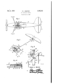
- Figure 1 is a fragmentary top plan view of an aeroplane, partially broken away to illustrate the invention therein;
- Figure 2 is a perspective view of the control connected to the elevators
- Figure 3 is a top plan view of the control.
- Figure 4 is a cross sectional view, taken substantially in the plane of the line 4-4 in Figure 2.
- the invention consists of an elevator control designated generally by the reference character it), such as may be conveniently and effectively employed for raising and lowering the elevators ll of a miniature aeroplane l2.
- This aircraft may be of any suitable type and includes a fuselage l3 to the tail portion of which the elevators H, which are adapted for simultaneous movement, are hingedly connected.
- the elevators ll may be rigidly secured to a shaft I3 which also carries a crank l4 disposed between the two elevators, as is indicated in Figure 2.
- An elevator rod l5 extends longitudinally in the fuselage IS, the end portions of the rod being angulated as at 16 and I1, and the end portion 18 being pivoted to the crank I4, as will be clearly understood.
- the control unit I0 includes a strip-like base plate l8 which is rigidly secured in the fuselage l3, and a substantially T-shaped lever i9 is pivoted by means of a screw 20 to the plate, as will be clearly apparent.
- the pivot screw 20 is disposed at the junction of the three arms of the T-shaped lever, while a pair of remote control cords 2
- are of sufficient length to extend to the operator, so that the aircraft may be efiectively controlled while in flight.
- the remaining, that is, the laterally projecting arm of the lever I9 is formed. with an open slot 23 in which a roller 24 is slidably positioned.
- This roller is of a disc-like configuration and is formed in the periphery thereof with a V-shaped groove 25, While the longitudinal edges of the slot 23 are chamfered to provide What may be called knife edges 26. These knife edges engage the groove of the roller, whereby the latter is not only effectively retained in position in the slot,
- the roller 24 is rotatably mounted between a pair of spaced parallel members constituting what may be called a crank 21, this crank being pivoted to the aforementioned base plate [8 by means of a further screw 28.
- the roller 24 itself is mounted upon the angulated portion ll of the aforementioned-rod l5, which angulated'portion extends through the members of the crank 21, as will be clearly apparent.
- a pair of upstanding stop pins 29 are provided on the base plate l8 for the purpose of restricting the-extent of movement of the lever 19.
- the elevators H When the invention is placed in use, the elevators H are intended to be disposed in ahorim zontal position when the pivot elements 20, I1 and 28 are in alignment, asillustrated in Figures 1 and 2.
- V 7
- an elevator control comprising a base plate mounted in said fuselage, a crank pivoted at one end thereof to said plate and operatively connected at its free end to said elevators, a substantially T- shaped lever having a pivot at the junction of its arms and being attached by said pivot to said plate, a pair of remote control cords connected to the longitudinally aligned arms of said lever, the laterally projecting arm of said lever being formed with an open slot, and a rotatable roller mounted on said free end of said crank, said'roller engaging the edges of said slot for guided movement of said crank therewithin.
Landscapes
- Toys (AREA)
Description
Dec. 6, 1949 H. MElS TER 9 3 TOY AIRPLANE CONTROL Filed July 9, 1947 I 11 mm [or hi3; Ill/A7451 Patented Dec. 6, 1949 UNITED STATES PATENT OFFICE TOY AIRPLANE CONTROL Honore L. Meister, Houston, Tex.
Application July 9, 1947, Serial No. 759,843
2 Claims. (Cl. 46-77) This invention relates to new and useful im'- provements and structural refinements in controls for toy aeroplanes, more specifically, in controls which constitute a component of the device disclosed in the United States Patent No. 2,292,416, granted to M. E. Walker on August 11, 1942.
In particular, this invention concerns itself with the particular control for elevating and depressing the elevators of the empennage, which, in the device of Walker are actuated by means of a rod connected to a crank pivoted in the fuselage. However, inasmuch as the effective movement of the elevator actuating rod is directly proportional to the movement of the crank, persons who are unskilled in handling the aeroplane often experience the tendency to actuate the crank too abruptly, thereby losing the relatively gradual touch and finesse in controlling the aircraft.
Steps have been taken to rectify this disadvantage by providing two or more points on the actuating crank to which the elevator rod may be selectively connected. As a result, the operator was able to use more abrupt or a more gradual control of the elevators, simply by attaching the elevator rod further from or closer to the pivot of the actuating crank.
However, an adjustment of this nature necessarily had to be undertaken while the aeroplane was on the ground and no means were provided for effecting such adjustment in flight.
It is, therefore, the principal object of the instant invention to eliminate the above outlined disadvantages by providingan elevator control which embodies means for varying the movement of the elevator with respect to the actuating crank or lever in a predetermined, variable ratio, which ratio may be effectively varied during flight.
A further object of the invention is to provide an elevator control which is simple in construction, which may be easily and conveniently manipulated, and which may be readily applied to new model aircraft, as well as those already in existence.
An additional object of the invention is to provide an elevator control which is light in weight, which will readily lend itself to economical manufacture, and which is otherwise well adapted for the purpose for which it is intended.
With the above more important objects in view and such other objects as may become apparent as this specification proceeds, the invention consists essentially of the construction and arrange- 2 ment of parts as shown in the accompanying drawings in which:
Figure 1 is a fragmentary top plan view of an aeroplane, partially broken away to illustrate the invention therein;
Figure 2 is a perspective view of the control connected to the elevators;
Figure 3 is a top plan view of the control; and
Figure 4 is a cross sectional view, taken substantially in the plane of the line 4-4 in Figure 2.
Like characters of reference are used to designate like parts in the specification and throughout the several views.
Referring now to the accompanying drawings in detail, the invention consists of an elevator control designated generally by the reference character it), such as may be conveniently and effectively employed for raising and lowering the elevators ll of a miniature aeroplane l2.
This aircraft may be of any suitable type and includes a fuselage l3 to the tail portion of which the elevators H, which are adapted for simultaneous movement, are hingedly connected.
In effect, the elevators ll may be rigidly secured to a shaft I3 which also carries a crank l4 disposed between the two elevators, as is indicated in Figure 2. An elevator rod l5 extends longitudinally in the fuselage IS, the end portions of the rod being angulated as at 16 and I1, and the end portion 18 being pivoted to the crank I4, as will be clearly understood.
The control unit I0 includes a strip-like base plate l8 which is rigidly secured in the fuselage l3, and a substantially T-shaped lever i9 is pivoted by means of a screw 20 to the plate, as will be clearly apparent. It should be noted that the pivot screw 20 is disposed at the junction of the three arms of the T-shaped lever, while a pair of remote control cords 2| are connected to the longitudinally aligned arms, as indicated at 22. The cords 2|, of course, are of sufficient length to extend to the operator, so that the aircraft may be efiectively controlled while in flight.
The remaining, that is, the laterally projecting arm of the lever I9 is formed. with an open slot 23 in which a roller 24 is slidably positioned. This roller is of a disc-like configuration and is formed in the periphery thereof with a V-shaped groove 25, While the longitudinal edges of the slot 23 are chamfered to provide What may be called knife edges 26. These knife edges engage the groove of the roller, whereby the latter is not only effectively retained in position in the slot,
3 but friction resulting from the sliding or rotation thereof is substantially minimized.
The roller 24 is rotatably mounted between a pair of spaced parallel members constituting what may be called a crank 21, this crank being pivoted to the aforementioned base plate [8 by means of a further screw 28. The roller 24 itself is mounted upon the angulated portion ll of the aforementioned-rod l5, which angulated'portion extends through the members of the crank 21, as will be clearly apparent.
Finally, it may be mentioned that a pair of upstanding stop pins 29 are provided on the base plate l8 for the purpose of restricting the-extent of movement of the lever 19.
When the invention is placed in use, the elevators H are intended to be disposed in ahorim zontal position when the pivot elements 20, I1 and 28 are in alignment, asillustrated in Figures 1 and 2. V 7
However, assuming that one of the cords, 2| is pulled in the direction of the arrow 30, the lever I9 will be swung about the pivot 20 in the direction of the arrow 3| and, at the same time, the crank 27 will be moved in the direction of the arrow 32. This is illustrated in the accompanying Figure 3, wherein it will be noted that the movement of the members I9 and 21 will be accompanied by the outward sliding movement of the ioller 24' in the slot 23, whereby the distance of the roller 24 from the pivot 20 will become progressively greater as the movement of the lever I9 continues. eedless to say, a similar condition presents itself when the lever I9 is swung in the relatively opposite direction, that is to say, to the right-hand side of the dead center line (4-4) normally established by the pivots 20, I! and 28, as viewed in Figure 2.
The essence of the invention resides in the predetermined, variable ratio of the extent of movement of the crank 21 with respect to that of the lever Hi, this, of course, being facilitated by the sliding of the roller 24 in the slot 23. That is to say, when the pivots 20, I! and 28 are disposed in alignment, the roller 24 will be as close to the pivot 20 as possible, and relatively large movement of the lever 19 will impart a relatively small movement to the roller 24, and through the me= dium of the rod Hi, to the elevators II. In this manner, finesseof control and precision flying at take-off and landing will be facilitated.
However, when the aircraft is in flight, considerable movement may be imparted to the lever 19, and since under such circumstances the roller 24 will be moved in the slot 23 as far as possible from the pivot 20, abrupt movement will be imparted to the elevators I I by virtue of the increased leverage. This abrupt control will, of course, be highly effective when encountering obstacles or during stunt flying.
It is believed that the advantages and use of the invention will be clearly understood from the foregoing disclosure and accordingly, further description thereof at this point is deemed unnecessary.
While in the foregoing there has been shown and described the preferred embodiment of this invention it is to be understood that minor changes in the details of construction, combination and arrangement of parts may be resorted to without departing from the spirit and scope of the. invention as claimed.
Having described the invention, what is claimed as new is:
1. In a toy aeroplane including a fuselage and a pair of simultaneously movable-elevators, an elevator control comprising a base plate mounted in said fuselage, a crank pivoted at one end thereof to said plate and operatively connected at its free end to said elevators, a substantially T- shaped lever having a pivot at the junction of its arms and being attached by said pivot to said plate, a pair of remote control cords connected to the longitudinally aligned arms of said lever, the laterally projecting arm of said lever being formed with an open slot, and a rotatable roller mounted on said free end of said crank, said'roller engaging the edges of said slot for guided movement of said crank therewithin.
2. The device as defined in claim 1 in which the periphery of said roller is formed with a V-shaped groove, the longitudinal edges of said slot being chamfered and providing knife edges to engage said roller within said groove.
HONORE L. MEISTER.
REFERENCES CITED The following references are of record in the file of this patent:
UNITED STATES PATENTS Number Name Date 1 1,791,070 Coggon Feb. 3, 1931 2,006,156 Bonanno 1 June 25, 1935 2,292,416 Walker Aug. 11, 1942 FOREIGN PATENTS Number Country Date 415,074 Great Britain Aug. 16, 1934
Priority Applications (1)
| Application Number | Priority Date | Filing Date | Title |
|---|---|---|---|
| US759843A US2490313A (en) | 1947-07-09 | 1947-07-09 | Toy airplane control |
Applications Claiming Priority (1)
| Application Number | Priority Date | Filing Date | Title |
|---|---|---|---|
| US759843A US2490313A (en) | 1947-07-09 | 1947-07-09 | Toy airplane control |
Publications (1)
| Publication Number | Publication Date |
|---|---|
| US2490313A true US2490313A (en) | 1949-12-06 |
Family
ID=25057167
Family Applications (1)
| Application Number | Title | Priority Date | Filing Date |
|---|---|---|---|
| US759843A Expired - Lifetime US2490313A (en) | 1947-07-09 | 1947-07-09 | Toy airplane control |
Country Status (1)
| Country | Link |
|---|---|
| US (1) | US2490313A (en) |
Cited By (3)
| Publication number | Priority date | Publication date | Assignee | Title |
|---|---|---|---|---|
| US2570316A (en) * | 1949-10-11 | 1951-10-09 | Jr William H Burks | Captive aircraft control |
| US3110126A (en) * | 1960-09-19 | 1963-11-12 | Gilbert Co A C | Overcontrol preventer for miniature captive airplanes |
| US20130130586A1 (en) * | 2011-09-30 | 2013-05-23 | Perdomo R. Orestes | Tether assembly for a radio frequency controlled aircraft |
Citations (4)
| Publication number | Priority date | Publication date | Assignee | Title |
|---|---|---|---|---|
| US1791070A (en) * | 1931-02-03 | Hakby fbow cookjolt | ||
| GB415074A (en) * | 1933-02-16 | 1934-08-16 | Charles Henry Lyde | Improvements in or relating to toy power boats |
| US2006156A (en) * | 1933-09-14 | 1935-06-25 | Lionel Corp | Self propelled toy |
| US2292416A (en) * | 1940-12-26 | 1942-08-11 | Nevilles E Walker | Controlled captive type toy airplane |
-
1947
- 1947-07-09 US US759843A patent/US2490313A/en not_active Expired - Lifetime
Patent Citations (4)
| Publication number | Priority date | Publication date | Assignee | Title |
|---|---|---|---|---|
| US1791070A (en) * | 1931-02-03 | Hakby fbow cookjolt | ||
| GB415074A (en) * | 1933-02-16 | 1934-08-16 | Charles Henry Lyde | Improvements in or relating to toy power boats |
| US2006156A (en) * | 1933-09-14 | 1935-06-25 | Lionel Corp | Self propelled toy |
| US2292416A (en) * | 1940-12-26 | 1942-08-11 | Nevilles E Walker | Controlled captive type toy airplane |
Cited By (3)
| Publication number | Priority date | Publication date | Assignee | Title |
|---|---|---|---|---|
| US2570316A (en) * | 1949-10-11 | 1951-10-09 | Jr William H Burks | Captive aircraft control |
| US3110126A (en) * | 1960-09-19 | 1963-11-12 | Gilbert Co A C | Overcontrol preventer for miniature captive airplanes |
| US20130130586A1 (en) * | 2011-09-30 | 2013-05-23 | Perdomo R. Orestes | Tether assembly for a radio frequency controlled aircraft |
Similar Documents
| Publication | Publication Date | Title |
|---|---|---|
| US2541922A (en) | Incidence angle adjustment for aircraft wings | |
| US3506220A (en) | Horizontal axis,flat lifting rotor and control system for aircraft | |
| US2404922A (en) | Miniature self-propelled airplane | |
| US2490313A (en) | Toy airplane control | |
| US4194317A (en) | Remotely controlled aircraft | |
| US2575886A (en) | Helicopter antitorque mechanism | |
| US2303965A (en) | String propelled toy airplane | |
| US3107452A (en) | Toy plane control device | |
| US2395530A (en) | Model airplane control | |
| US2491825A (en) | Control handle for toy airplanes | |
| US2526371A (en) | Airplane flight instruction device | |
| US2472075A (en) | Flying kite and control | |
| US2499666A (en) | Model airplane launching apparatus | |
| US2299582A (en) | Flight control system for miniature aircraft | |
| US2645882A (en) | Retractable landing gear for model planes | |
| US2584588A (en) | Landing gear and flap control for tethered model airplanes | |
| US2602604A (en) | Manual control and reel for tethered powered model airplanes | |
| US2323506A (en) | Miniature airplane | |
| US2538132A (en) | String propelled toy airplane and control device therefor | |
| US2849833A (en) | Tethered model airplanes | |
| US2736133A (en) | carpenter | |
| US2410726A (en) | Flying propeller toy | |
| US2527274A (en) | Ratio control for captive airplanes | |
| FR2697442A1 (en) | Device for controlling gliding flight of bird-like aircraft - controls flight using combinations in proportion of tail movements, body position changes and twisting and folding of wings | |
| US2714783A (en) | Pressure flight control for miniature airplane |