US2490210A - Chair base - Google Patents
Chair base Download PDFInfo
- Publication number
- US2490210A US2490210A US579526A US57952645A US2490210A US 2490210 A US2490210 A US 2490210A US 579526 A US579526 A US 579526A US 57952645 A US57952645 A US 57952645A US 2490210 A US2490210 A US 2490210A
- Authority
- US
- United States
- Prior art keywords
- roller
- leg
- legs
- casters
- chair
- Prior art date
- Legal status (The legal status is an assumption and is not a legal conclusion. Google has not performed a legal analysis and makes no representation as to the accuracy of the status listed.)
- Expired - Lifetime
Links
- 238000010276 construction Methods 0.000 description 6
- 229910000838 Al alloy Inorganic materials 0.000 description 2
- 229910000861 Mg alloy Inorganic materials 0.000 description 2
- 238000009411 base construction Methods 0.000 description 2
- 239000002689 soil Substances 0.000 description 2
- FYYHWMGAXLPEAU-UHFFFAOYSA-N Magnesium Chemical compound [Mg] FYYHWMGAXLPEAU-UHFFFAOYSA-N 0.000 description 1
- XAGFODPZIPBFFR-UHFFFAOYSA-N aluminium Chemical compound [Al] XAGFODPZIPBFFR-UHFFFAOYSA-N 0.000 description 1
- 238000004512 die casting Methods 0.000 description 1
- 239000000428 dust Substances 0.000 description 1
- 239000004744 fabric Substances 0.000 description 1
- 239000011777 magnesium Substances 0.000 description 1
- 238000004519 manufacturing process Methods 0.000 description 1
- 239000000463 material Substances 0.000 description 1
- 229910052751 metal Inorganic materials 0.000 description 1
- 239000002184 metal Substances 0.000 description 1
- 238000000034 method Methods 0.000 description 1
- 238000005728 strengthening Methods 0.000 description 1
Images
Classifications
-
- A—HUMAN NECESSITIES
- A47—FURNITURE; DOMESTIC ARTICLES OR APPLIANCES; COFFEE MILLS; SPICE MILLS; SUCTION CLEANERS IN GENERAL
- A47C—CHAIRS; SOFAS; BEDS
- A47C7/00—Parts, details, or accessories of chairs or stools
- A47C7/002—Chair or stool bases
- A47C7/004—Chair or stool bases for chairs or stools with central column, e.g. office chairs
Definitions
- This invention relates to bases for chairs of the swivel type and more particularly to a chair base having a plurality of radially extending legs the outer extremities of which are provided with supporting casters.
- a further object is to provide a novel chair base construction of the above character wherein the casters are partially concealed by the chair legs in such a manner as to avoid any scufling and soiling of the users shoes.
- Another object resides in the provision of a novel arrangement in a caster-mounted chair base wherein the casters are shielded from contact with the users shoes and wherein complete swiveling of the casters is enabled without increasing the width of the chair legs, thus presenting a strong and sturdy base having a compact and attractive appearance.
- a still further object includes a novel construction and arrangement of parts in a chair base of the foregoing type wherein protection of the shoes of the user is achieved without causing instability of construction or a bulky and unsightly appearance.
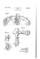
- Fig. 1 is a side view of a chair base constructed in accordance with the present invention, a portion of the base being shown in section to more clearly illustrate the leg structure;
- Fig. 2 is a plan view of a portion of the base, the caster roller associated with the legs being shown in dotted lines in two positions at right angles to each other, certain parts having been omitted for clarity of illustration;
- Fig. 3 is a vertical sectional view of one of the legs taken substantially along lines 3-3 of Fig. l, and
- Fig. 4 is a vertical sectional view taken substantially along lines 4-4 of Fig. 1 and showing the arrangement of the parts when the caster is moved to a position at right angles to that illustrated inFig. 1.
- a chair base constructed in accordance with the present invention is illustrated therein as comprising a central hub portion l0 having a plurality of outwardly-extending legs l2 radiating therefrom, the latter bein preferably four in number and being integrally formed with said hub portion.
- a desired method of manufacture is to provide an integral die-casting of magnesium or aluminum alloy which includes the hub and legs, but it will be understood that if desired, the legs may be made separately from the hub and se cured to the latter in a convenient manner.
- the hub I 0 is provided with a centrally arranged socket H for receiving a tubular member 16 which may be fixed in position by a screw l8, it being understood that a suitable seat structure, not shown, is mounted torswivel upon the upper end of mannermember 16 in well-known.
- the ribs 26 are undercut at 28 and. reduced in width at 30 in order to accommodate channel-shaped strips 32 which may be secured" to each leg as by means ofiscrews. 314.
- Each or; these strips while preferably constructed of light-weight metal such, as aluminum or magnesium alloy, may nevertheless be constituted of' any suitable material, and 'may-be-of a diflerent color than'that or the chair legs, if desired, in order to present a pleasing and ornamental appearance.
- each leg l2 is provided adjacent its outer extremity with a strengthening block 36, which is preferably formed integrally with the leg and curved-orroundedin two planes at right angles as illustrated in Figs. 1 and 4'.
- Each block 36 is provided with-an opening 31' for receiving a support 3% for a caster- 4D; the latter being of thewell-known trailing type and including a roller 42:
- caster and chair leg may be-more particularly observed from a consideration of Figs. 1" and-4 of the drawings wherein it will be seenthatthe extreme outer and lower portion 44- of" the legisbrought downwardly'a substantial distance'below the top of the roller 42-as definedbya horizontal plane tangent tothe'top-of't-he roller;
- the extent to which the portion 44 conceals the roller 42 is suflicient to prevent contact between the roller and the shoes of the-user,- andin this con nection it is pointed out that in the position shown in Fig. 1 where the roller extends forwardly its maximum amount, the-forward portion of its periphreyis positioned slightly inwardly of the portion 44.
- the outer and lower-most portions 46 and 48 of the s'ide sections 20- and 22" respectively are cut away in such a manner as to extend upwardly from a horizontal plane beginning at the lower lip of portion 44 and terminating at the junctureswiththe-side sections 20 and 22, as illustrated.
- the present invention provides a novel chair base construction which is so arranged that contact between the. caster rollers and the user's shoes is effectively prevented.
- the structure moreover is such that complete rotation of the casters may be effected without increasing the leg width, thus securing a stable and sturdy construction, and one. whichv is not unduly bulky in appearance.
- the attractiveness and commercial sales value of the base is materially enhanced by the advantageous construction employed, it being particularly observed that practically the entire caster structure including a portion of the roller top is concealed from view, resulting in a streamlined appearance having the new and improved functional aspects hereinbefore referred to.
- a pocket or recess 58 is provided at the outer and lower-most extremity of each leg which houses a substantial portion of the caster 49'as well as the upper part of the roller :2, the pocket being in efiect, constituted by a base comprising the lower surface of the block 35 bounded by a curved wall which is cut back from the outer portion to the inner portion to permit the aforesaid complete rotation of the casters about their mountings 38.
- a chair base comprising a hub having a plurality of legs extending outwardly therefrom, the outer end of each leg being provided with downwardly extending outer end'and spaced apart side walls defining a pocket, a caster mounted to swivel at the'outer end portion of each leg, each caster including a frame housed'within said pocket, and a roller mounted to rotate on the frame, the said outer end wall extending downwardly below the top of the roller and outwardly beyond the periphery of the roller when the latter is side walls being spaced apart a distance such that the outer extremity of the periphery of the roller projects beyond the lower edges of the side walls when the roller is moved to either position at right angles to the axis of a leg, and said side walls having lower edges directed upwardly at an angle to a horizontal plane from the outermost to the innermost portions thereof to permit cornplete rotation of the casters without the rollers contacting said edges.
- a chair base comprising a central support and a plurality of outwardly extending legs each of which is provided with a centrally disposed rib on its upper surface extending from one end to'the other, a substantial portion of the outer end of the rib being reduced in width and thickne'ss a slight amount, a caster-receiving opening extending through the outer end of each leg and through each rib, and a channel-shaped strip removably' secured to said reduced: portion ofthe rib and covering said opening, said strip having an inturned lip engaging the outer lower edge of the rib.
- a chair base comprising a hub having a plurality of legs extending outwardly therefrom, the outer end of each leg being provided with a socket, a caster mounted to swivel in said socket, said caster being provided with a rotatably mounted roller, and each leg being provided with an integral extension projecting below the top of the roller and beyond the periphery of the latter when the roller is aligned with each respective leg, whereby the shoes of a chair user are protected from contacting the roller, each of said legs being also provided with a pair of integral side wall portions extending below the top of each roller and being spaced apart a distance such that the outer extremity of the periphery of the roller projects slightly beyond the lower edges of the side wall portions when the roller is moved to either position at right angles to the axis of a leg, the lower edges of said portions being cut away at an angle to the horizontal plane from the outermost to the innermost portions thereof, to allow free and complete rotation of the casters without the rollers contacting said edges.
- a chair base comprising a unitary structure having a plurality of outwardly extending legs, the outer ends of each being provided with swivelling casters including frames having rollers rotatably mounted therein, and means to prevent contact between the shoes of the chair user and to allow complete swivelling of said casters
- a housing for each caster said housing including end and side walls formed integrally with each leg, the low-er edges of said walls terminating above the rotatable axis of the roller and below the top of the roller, the lower edges of the side walls being spaced apart a distance such that the outer extremity of the periphery of the roller projects slightly beyond the lower edges of the side walls when the roller is moved to either position at right angles to the axis of a leg, and said side walls being cut away to provide lower edges sloping upwardly from the outer to the inner portions thereof whereby complete swivelling of the casters is permitted and the lower edges of the end and side walls are closely spaced from the periphery of the
Landscapes
- Chair Legs, Seat Parts, And Backrests (AREA)
Description
DEC. 6, 1949 R, M R ET AL 2,490,210
CHAIR BASE Filed Feb. 24, 1945 IEQZ 16 P I 10 r 32 x I 26 4 4 24 32 ad 34 I, 34' 3 9O 12 16 20 Z2 12 I, 36 46\ Q2 I 7 :1 44 40% q 40 42 42 j I IN V EN TORS 40 Roy A Craucer Harald WCraznJ' BY Roy A. Cranler, .]r.
ATTORNEYS Patented Dec. 6, 1949 CHAIR BASE Roy A. Cramer, Harold W. Cramer, and Roy A.
Cramcr, Jr., Kansas City, Mo. 7
Application February 24, 1945, Serial No. 579,526 4 Claims. (01.248-194) This invention relates to bases for chairs of the swivel type and more particularly to a chair base having a plurality of radially extending legs the outer extremities of which are provided with supporting casters.
Chairs of the type having swiveling seats and bases provided with radiating legs have long been provided adjacent the outer extremities of the legs, with supporting casters. However, such casters have heretofore been mounted in such a manner as to partially project beyond the surface of the ends of the legs, and thus have presented obstructions which mar, scuif or soil the shoes of the user. Such an arrangement of casters is especially objectionable when it is borne in mind that the caster rollers are generally made of rubber which rubs off and thus scuffs and soils white or cloth shoes of any color. Moreover, the caster rollers pick up dirt and dust from the floor which is transferred to the users shoes, thus contributing to the soiling thereof whenever the shoes accidentally contact the casters. While the disadvantages referred to could be avoided by completely housing the casters within the chair legs, still such an arrangement would cause an excessively bulky structure and would materially detract from its appearance, attractiveness and sales value. In addition, a construction of the latter type would necessitate bringing the sides and ends of the legs down so close to the floor as to be undesirable for use with floor coverings such as thick rugs.
It is accordingly one of the objects of the present invention to provide a chair base having a plurality of radiating legs provided at their outer extremities with casters which are so constructed and arranged as to avoid the aforementioned objectionable features and disadvantages.
A further object is to provide a novel chair base construction of the above character wherein the casters are partially concealed by the chair legs in such a manner as to avoid any scufling and soiling of the users shoes.
Another object resides in the provision of a novel arrangement in a caster-mounted chair base wherein the casters are shielded from contact with the users shoes and wherein complete swiveling of the casters is enabled without increasing the width of the chair legs, thus presenting a strong and sturdy base having a compact and attractive appearance.
A still further object includes a novel construction and arrangement of parts in a chair base of the foregoing type wherein protection of the shoes of the user is achieved without causing instability of construction or a bulky and unsightly appearance.
Other objects and novel features of the invention will appear more fully hereinafter from a consideration of the following detailed descrip tion when taken in connection with the accompanying drawing illustrative of a preferred form of the invention. It is to be expressly understood, however, that the drawing is employed for purposes of illustration only and is not designed as a definition of the limits of the invention, reference being had for this purpose to the appended claims.
Referring to the drawing wherein similar reference characters refer to similar parts throughout the several views:
Fig. 1 is a side view of a chair base constructed in accordance with the present invention, a portion of the base being shown in section to more clearly illustrate the leg structure;
Fig. 2 is a plan view of a portion of the base, the caster roller associated with the legs being shown in dotted lines in two positions at right angles to each other, certain parts having been omitted for clarity of illustration;
Fig. 3 is a vertical sectional view of one of the legs taken substantially along lines 3-3 of Fig. l, and
Fig. 4 is a vertical sectional view taken substantially along lines 4-4 of Fig. 1 and showing the arrangement of the parts when the caster is moved to a position at right angles to that illustrated inFig. 1.
Referringmore particularly to Figs. 1 and 2, a chair base constructed in accordance with the present invention is illustrated therein as comprising a central hub portion l0 having a plurality of outwardly-extending legs l2 radiating therefrom, the latter bein preferably four in number and being integrally formed with said hub portion. A desired method of manufacture is to provide an integral die-casting of magnesium or aluminum alloy which includes the hub and legs, but it will be understood that if desired, the legs may be made separately from the hub and se cured to the latter in a convenient manner. As shown, the hub I 0 is provided with a centrally arranged socket H for receiving a tubular member 16 which may be fixed in position by a screw l8, it being understood that a suitable seat structure, not shown, is mounted torswivel upon the upper end of mannermember 16 in well-known.
all of such sections merging into the base, as.
shown in Fig. 2, and extending the full length of each leg. Adjacent the outer ends of the legs,
however, the ribs 26 are undercut at 28 and. reduced in width at 30 in order to accommodate channel-shaped strips 32 which may be secured" to each leg as by means ofiscrews. 314. Each or; these strips, while preferably constructed of light-weight metal such, as aluminum or magnesium alloy, may nevertheless be constituted of' any suitable material, and 'may-be-of a diflerent color than'that or the chair legs, if desired, in order to present a pleasing and ornamental appearance. a
Oneofthe features-'ofthe present inventionresides in the provision of a novel arrangementfor mounting casters inthe outer ends of the chair legs in such manner as-to-effectively prevent contact between the casters andthe users shoes while enabling complete rotation of the casters without increasing thechair leg; width to a degree resulting in a bulky and unattractive appearance. To this end, each leg l2 is provided adjacent its outer extremity with a strengthening block 36, which is preferably formed integrally with the leg and curved-orroundedin two planes at right angles as illustrated in Figs. 1 and 4'. Each block 36 is provided with-an opening 31' for receiving a support 3% for a caster- 4D; the latter being of thewell-known trailing type and including a roller 42:
The novel and advantageous arrangement of caster and chair leg may be-more particularly observed from a consideration of Figs. 1" and-4 of the drawings wherein it will be seenthatthe extreme outer and lower portion 44- of" the legisbrought downwardly'a substantial distance'below the top of the roller 42-as definedbya horizontal plane tangent tothe'top-of't-he roller; The extent to which the portion 44 conceals the roller 42 is suflicient to prevent contact between the roller and the shoes of the-user,- andin this con nection it is pointed out that in the position shown in Fig. 1 where the roller extends forwardly its maximum amount, the-forward portion of its periphreyis positioned slightly inwardly of the portion 44.
In order that the caster 40- may swivel throughout 360 degrees, without necessitating an excessivewidth of the end of each chair leg, the outer and lower-most portions 46 and 48 of the s'ide sections 20- and 22" respectively, instead of extending rearwardlyfromthepurtion 44 in a horizontal plane, are cut away in such a manner as to extend upwardly from a horizontal plane beginning at the lower lip of portion 44 and terminating at the junctureswiththe-side sections 20 and 22, as illustrated. Thus, with :such an arrange}- ment, the portionsriphery of the rollers-thercof-andthe'said'por tions. While the roller, 4-2- projects slightly be;
yondthe exterior of the-leg I! when therolle'r is at right angles to the position occupied in Fig.
7 46 and 48 are sufficiently cut back at'an-angle as to allow complete rotation of' 1, as shown in Figs. 2 and 4, this is not objectionable since the roller is then positioned a substantial distance from the outer extremity of the chair leg and not in a position to be engaged by the users shoes.
It will thus be observed from the foregoing that the present invention provides a novel chair base construction which is so arranged that contact between the. caster rollers and the user's shoes is effectively prevented. The structure moreover is such that complete rotation of the casters may be effected without increasing the leg width, thus securing a stable and sturdy construction, and one. whichv is not unduly bulky in appearance. The attractiveness and commercial sales value of the base is materially enhanced by the advantageous construction employed, it being particularly observed that practically the entire caster structure including a portion of the roller top is concealed from view, resulting in a streamlined appearance having the new and improved functional aspects hereinbefore referred to. It is to be particularly observed that by the construction including the outer and lower end portion 44 together with the portions 48 and 48, a pocket or recess 58 is provided at the outer and lower-most extremity of each leg which houses a substantial portion of the caster 49'as well as the upper part of the roller :2, the pocket being in efiect, constituted by a base comprising the lower surface of the block 35 bounded by a curved wall which is cut back from the outer portion to the inner portion to permit the aforesaid complete rotation of the casters about their mountings 38.
While one embodiment of the invention has been shown and; described herein with considerable particularity, it will be understood that various changes may be made therein without departing from the scope of theinvention, as will now appear to those skilled in the art. Reference will therefore be had to the appended claims for a definition of the limits of the invention.
What is claimed is:
' l. A chair base comprising a hub having a plurality of legs extending outwardly therefrom, the outer end of each leg being provided with downwardly extending outer end'and spaced apart side walls defining a pocket, a caster mounted to swivel at the'outer end portion of each leg, each caster including a frame housed'within said pocket, and a roller mounted to rotate on the frame, the said outer end wall extending downwardly below the top of the roller and outwardly beyond the periphery of the roller when the latter is side walls being spaced apart a distance such that the outer extremity of the periphery of the roller projects beyond the lower edges of the side walls when the roller is moved to either position at right angles to the axis of a leg, and said side walls having lower edges directed upwardly at an angle to a horizontal plane from the outermost to the innermost portions thereof to permit cornplete rotation of the casters without the rollers contacting said edges.
'2. A chair base comprising a central support and a plurality of outwardly extending legs each of which is provided with a centrally disposed rib on its upper surface extending from one end to'the other, a substantial portion of the outer end of the rib being reduced in width and thickne'ss a slight amount, a caster-receiving opening extending through the outer end of each leg and through each rib, and a channel-shaped strip removably' secured to said reduced: portion ofthe rib and covering said opening, said strip having an inturned lip engaging the outer lower edge of the rib.
3. A chair base comprising a hub having a plurality of legs extending outwardly therefrom, the outer end of each leg being provided with a socket, a caster mounted to swivel in said socket, said caster being provided with a rotatably mounted roller, and each leg being provided with an integral extension projecting below the top of the roller and beyond the periphery of the latter when the roller is aligned with each respective leg, whereby the shoes of a chair user are protected from contacting the roller, each of said legs being also provided with a pair of integral side wall portions extending below the top of each roller and being spaced apart a distance such that the outer extremity of the periphery of the roller projects slightly beyond the lower edges of the side wall portions when the roller is moved to either position at right angles to the axis of a leg, the lower edges of said portions being cut away at an angle to the horizontal plane from the outermost to the innermost portions thereof, to allow free and complete rotation of the casters without the rollers contacting said edges.
4. A chair base comprising a unitary structure having a plurality of outwardly extending legs, the outer ends of each being provided with swivelling casters including frames having rollers rotatably mounted therein, and means to prevent contact between the shoes of the chair user and to allow complete swivelling of said casters comprising a housing for each caster, said housing including end and side walls formed integrally with each leg, the low-er edges of said walls terminating above the rotatable axis of the roller and below the top of the roller, the lower edges of the side walls being spaced apart a distance such that the outer extremity of the periphery of the roller projects slightly beyond the lower edges of the side walls when the roller is moved to either position at right angles to the axis of a leg, and said side walls being cut away to provide lower edges sloping upwardly from the outer to the inner portions thereof whereby complete swivelling of the casters is permitted and the lower edges of the end and side walls are closely spaced from the periphery of the roller during such swivelling.
ROY A. CRAMER.
HAROLD W. CRAMER.
ROY A. CRAMER, JR.
REFERENCES CITED The following references are of record in the file of this patent:
UNITED STATES PATENTS Number Name Date 1,810,817 Brainard et a1 June 16, 1931 2,046,384 Katcher July '7, 1936 2,256,677 Jones Sept. 23, 1941 2,350,399 Jones June 6, 1944
Priority Applications (1)
| Application Number | Priority Date | Filing Date | Title |
|---|---|---|---|
| US579526A US2490210A (en) | 1945-02-24 | 1945-02-24 | Chair base |
Applications Claiming Priority (1)
| Application Number | Priority Date | Filing Date | Title |
|---|---|---|---|
| US579526A US2490210A (en) | 1945-02-24 | 1945-02-24 | Chair base |
Publications (1)
| Publication Number | Publication Date |
|---|---|
| US2490210A true US2490210A (en) | 1949-12-06 |
Family
ID=24317258
Family Applications (1)
| Application Number | Title | Priority Date | Filing Date |
|---|---|---|---|
| US579526A Expired - Lifetime US2490210A (en) | 1945-02-24 | 1945-02-24 | Chair base |
Country Status (1)
| Country | Link |
|---|---|
| US (1) | US2490210A (en) |
Cited By (11)
| Publication number | Priority date | Publication date | Assignee | Title |
|---|---|---|---|---|
| US2641310A (en) * | 1950-04-08 | 1953-06-09 | Reflectone Corp | Mounting member for furniture and the like |
| US2780431A (en) * | 1953-09-22 | 1957-02-05 | Sheldon & Co E H | Furniture pedestal base |
| US2939514A (en) * | 1956-08-06 | 1960-06-07 | Prec Metal Workers | Chair base and seat post adjustment |
| US2989280A (en) * | 1957-12-03 | 1961-06-20 | Emil J Paidar Company | Electro-mechanical beauty chair |
| US2992803A (en) * | 1955-08-12 | 1961-07-18 | Harter Corp | Base or pedestal for chairs |
| US3137512A (en) * | 1961-08-11 | 1964-06-16 | Carpezzi Leo Joseph | Height adjustable dolly |
| USD356913S (en) | 1993-10-26 | 1995-04-04 | Steelcase Inc. | Table base |
| US5692715A (en) * | 1994-03-14 | 1997-12-02 | Plastic Prescriptions Limited | Chair base having dual-tapered locking hub |
| USD416406S (en) | 1998-05-18 | 1999-11-16 | Donati, S.p.A. | Base for office chair |
| USD498611S1 (en) | 2003-11-21 | 2004-11-23 | Benq Corporation | Stand |
| US20140008888A1 (en) * | 2012-07-03 | 2014-01-09 | Harvey P. FINK | Guard for wheeled base |
Citations (4)
| Publication number | Priority date | Publication date | Assignee | Title |
|---|---|---|---|---|
| US1810817A (en) * | 1930-08-07 | 1931-06-16 | Gen Fireproofing Co | Base for swivel chairs |
| US2046384A (en) * | 1933-08-01 | 1936-07-07 | Samuel Bonat & Harry Bonat | Dirtproof caster |
| US2256677A (en) * | 1940-03-28 | 1941-09-23 | Art Metal Construction Co | Base for swivel chairs and the like |
| US2350399A (en) * | 1941-07-31 | 1944-06-06 | Posture Res Corp | Chair base |
-
1945
- 1945-02-24 US US579526A patent/US2490210A/en not_active Expired - Lifetime
Patent Citations (4)
| Publication number | Priority date | Publication date | Assignee | Title |
|---|---|---|---|---|
| US1810817A (en) * | 1930-08-07 | 1931-06-16 | Gen Fireproofing Co | Base for swivel chairs |
| US2046384A (en) * | 1933-08-01 | 1936-07-07 | Samuel Bonat & Harry Bonat | Dirtproof caster |
| US2256677A (en) * | 1940-03-28 | 1941-09-23 | Art Metal Construction Co | Base for swivel chairs and the like |
| US2350399A (en) * | 1941-07-31 | 1944-06-06 | Posture Res Corp | Chair base |
Cited By (12)
| Publication number | Priority date | Publication date | Assignee | Title |
|---|---|---|---|---|
| US2641310A (en) * | 1950-04-08 | 1953-06-09 | Reflectone Corp | Mounting member for furniture and the like |
| US2780431A (en) * | 1953-09-22 | 1957-02-05 | Sheldon & Co E H | Furniture pedestal base |
| US2992803A (en) * | 1955-08-12 | 1961-07-18 | Harter Corp | Base or pedestal for chairs |
| US2939514A (en) * | 1956-08-06 | 1960-06-07 | Prec Metal Workers | Chair base and seat post adjustment |
| US2989280A (en) * | 1957-12-03 | 1961-06-20 | Emil J Paidar Company | Electro-mechanical beauty chair |
| US3137512A (en) * | 1961-08-11 | 1964-06-16 | Carpezzi Leo Joseph | Height adjustable dolly |
| USD356913S (en) | 1993-10-26 | 1995-04-04 | Steelcase Inc. | Table base |
| US5692715A (en) * | 1994-03-14 | 1997-12-02 | Plastic Prescriptions Limited | Chair base having dual-tapered locking hub |
| USD416406S (en) | 1998-05-18 | 1999-11-16 | Donati, S.p.A. | Base for office chair |
| USD498611S1 (en) | 2003-11-21 | 2004-11-23 | Benq Corporation | Stand |
| US20140008888A1 (en) * | 2012-07-03 | 2014-01-09 | Harvey P. FINK | Guard for wheeled base |
| US8684375B2 (en) * | 2012-07-03 | 2014-04-01 | Harvey S. Fink | Guard for wheeled base |
Similar Documents
| Publication | Publication Date | Title |
|---|---|---|
| USD274675S (en) | Chair | |
| US3894496A (en) | Folding lawn chair table | |
| US4131315A (en) | Chair with deformable armrest | |
| US2364647A (en) | Chair construction | |
| USD598668S1 (en) | Chair | |
| US3669497A (en) | Chairs | |
| USD1000852S1 (en) | Folding chair with sunshade | |
| USD353268S (en) | Chair | |
| USD292146S (en) | Seat | |
| US2362746A (en) | Chair | |
| US3752533A (en) | Upholstered seat | |
| US2256677A (en) | Base for swivel chairs and the like | |
| US4365839A (en) | Chair construction with protective cushioning for exposed structural projections | |
| USD311129S (en) | Golf cart umbrella bracket | |
| US2334297A (en) | Convertible article of furniture | |
| USD359823S (en) | Combined carpet and floor dryer | |
| USD263902S (en) | Arm chair | |
| KR20210149672A (en) | A Chair with a Back Folded | |
| USD266973S (en) | Seat | |
| US3914810A (en) | Bed frame member | |
| US3610687A (en) | Chair | |
| US2210471A (en) | Vacuum cleaner casing | |
| US2630858A (en) | Chair construction | |
| US2263209A (en) | Chair | |
| USD274482S (en) | Seat |