US2487828A - Gun sight - Google Patents
Gun sight Download PDFInfo
- Publication number
- US2487828A US2487828A US601288A US60128845A US2487828A US 2487828 A US2487828 A US 2487828A US 601288 A US601288 A US 601288A US 60128845 A US60128845 A US 60128845A US 2487828 A US2487828 A US 2487828A
- Authority
- US
- United States
- Prior art keywords
- gun
- plane
- superelevation
- dial
- position angle
- Prior art date
- Legal status (The legal status is an assumption and is not a legal conclusion. Google has not performed a legal analysis and makes no representation as to the accuracy of the status listed.)
- Expired - Lifetime
Links
Images
Classifications
-
- F—MECHANICAL ENGINEERING; LIGHTING; HEATING; WEAPONS; BLASTING
- F41—WEAPONS
- F41G—WEAPON SIGHTS; AIMING
- F41G3/00—Aiming or laying means
Definitions
- FIG.2 GUN SIGHT v Filed June 25, i945 e sheets-sheet 2 FIG.2
- This invention relates to means for training guns on aircraft and more particularly to a manual system for the control of antiaircraft fire in which plane speed and altitude, as well as shell fuse setting, are translated into sgperele- /vation on thegunswithpptrecoursetoantift ⁇ tlg1 ets or sightsettingtables.
- the gun trailing means here cirsidered is designed for those guns whichA arenanuallwy gner ated as distinguished from those automatically controlled, though the latter may be euipped therewith to enable the guns to be used in the event of the failure of the automatic equipment. Installations in which antiaircraft guns are manually trained are usually found on such vessels as merchantmen, cutters, and corvettes, as well as in many land batteries.
- Dual purpose guns heretofore used have been provided with a range drum for superelevating the gun to the position corresponding to the range in yards to the target in a horizontal plane.
- the sight scales are graduated in minutes of arc and are set directly in terms of superelevation. This sight scale is on the sword arm aiiixed to the sight bar.
- the method of sighting now practiced for a manually operated gun, when used against aircraft, requires the services of about seven men, ve at the gun and two on the bridge. As air attacks are incredibly swift all members of the gun crew must be at their stations ready for action when the attack begins, a condition seldom realized in practice.
- the pointer and trainer must get the plane in the sights, the observer and plotter must determine plane speed and elevation and calculate the range from the line -of sight barrage curves for a selected fuse setting.
- This data is transmitted to the sightsetter who puts it on the gun.
- the dead time i. e. the time allowed for making observations and calculations and setting the gun sights, is about ive seconds, so if the plane takes '7 seconds to pass from one zone to another there remains but 2 seconds in which the gun may be fired and, as a good gun crew can re only 20 shots per minute from a 3" gun, it will be seen that only one or two aimed shots may be had for any given fuse setting.
- the sight bar is hinged to the top of the sleeve which supports the gun barrel.
- the sleeve is provided with trunnions enabling the gun to be raised and lowered in a vertical plane and the trunnions rest on a base mounted for rotation so that the gun may be rotated in a horizontal plane.
- This sight bar has two sighting means thereon, one on each side of the gun, by means of which a pointer and a trainer keep the aircraft in their respective sights by rotating the gun in a horizontal plane and in a vertical plane.
- the axis of the gun barrel and the line of sight established by the sighting means do not coincide and the angle therebetween is designated as the superelevation, or angle of I elevation, of the gun.
- This superelevation is determined by the speed, elevation and distance of the target as well as the shell trajectories and since explosive shells are used the fuse must be set to explode the shell at the proper time.
- the fuse settings of the shells are for 2, 4, 6 and 8 seconds and the superelevation calculations for barrages to be set up at rangesl corresponding to the fuse settings are termed zones,
- the degree of superelevation of the gun is determined by an instrument which supplants the range drum heretofore used and can be readily installed on existing guns by a simple substitution of parts.
- This instrument integrates plane speed, fuse setting and position angle directly into superelevation in one operation and obviates recourse to tracking sheets or charts and eliminates the dead time resulting therefrom. Characteristics inherent in the system permit the operators readily to detect and correct errors in judgment in estimating the speed of the target, the only factor which must be estimated.
- a further object of this invention is to provide means for visually indicating the position angle of the target.
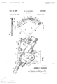
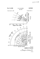
- Fig. 1 is a side elevation of conventional 3" dual purpose gun showing the instrument and the position angle indicator mounted thereon.
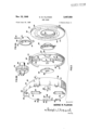
- Fig. 2 is an exploded perspective view of the principal parts of the instrument drawn on a reduced scale.
- Fig. 2a is a perspective View of one of the members supporting the dial 62 and is drawn on the same scale as Fig. 2.
- Fig. 2b is a perspective view of the shaft and gear for carrying and driving the dial of the instrument and is drawn on the same scale as Fig. 2.
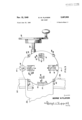
- Fig. 3 is an elevation of the instrument as it appears mounted on the gun and is drawn to the same scale as Fig. 2.
- Fig. 4 is a sectional view along the line 4-4 of Fig. 3.
- Figs. 5, 6 and 7 are full scale drawings of the transparent curve charts upon which are inscribed the position angle curves for zones 2, 4 and 8, respectively, and are calibrated for use with a 3" 50 caliber gun and 13 pound antiaircraft projectiles having a 30 second mechanical time fuse.
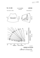
- Fig. 8 is a simplified trajectory chart for the gun shown in Fig. 1 and firing 13 pound antiaircraft projectiles having an initial velocity of 2615 feet per second.
- Fig. 9 is a chart of position angle versus superelevation for the range of speeds indicated and is constructed from data taken from the chart shown in Fig. 8 for use in determining the position angle curves for zone 8 as shown in Fig. 7.
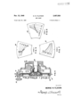
- Fig. 10 is an elevation of a position angle indicator.
- Fig. 11 is a cross section taken along the line II-I I, Fig. 10.
- Figs. 12 to 14 relate to a modified method of Calibrating the gun sight.
- Fig. 1 shows a 3" gun equipped with means ernbodying the principles of the instant invention for training the gun on an aerial target.
- the gun is of conventional type and of the kind found on most non-combatant ships now afloat. It has a barrel II slidably mounted in a sleeve, or slide, I2 which carries trunnions I3 journaled on the base I4 which is adapted .to be rotated in a horizontal plane.
- the sight bar I6 is pivotally mounted on a shaft I1 attached to the sleeve I2.
- This bar has a pointing sight I8 carried by a bracket 2
- a similar training sight (not shown) is aixed to the sight bar on the other side of the sleeve. These sights are kept on the target at all times by proper manipulation of the gun by the pointer and trainer.
- a sword arm 22 is affixed to the end of the sight bar I6, projecting downwardly therefrom, and passes through a fixture 23 carried by, and attached to, the sleeve I2.
- Gear teeth 24 on the sword arm mesh with a gear (not shown) operated by a hand wheel 25 whereby the angular position ⁇ of the sight bar may be varied with respect to that of the gun, the difference in such angular position, angle S in Fig. 1, being designated as the superelevation on the gun.
- the position angle of the target, angle P is the angle the sight bar makes with the horizontal plane when trained on the target.
- the difference in angular position of the gun barrel II, i. e. firing angle, and the sight bar I6 is due to the fact that the trajectory of the shell red by the gun is curved rather than straight. The line of sight, therefore, forms the chord to the curved path of the shell.
- the degree of superelevation required for any given target is indicated by the instrument 26.
- a position angle indicator 21 is carried by the sight bar I6 to furnish part of the information required by the sightsetter who operates the instrument.
- the customary means for correcting for deflection is provided in the deiiection drum 28 and hand wheel 29, the operation of which serves to move the sight bar in a direction normal to that caused by the manipulation of hand wheel 25.
- the instrument 26, shown in detail in Figs. 2, 3 and 4 comprises a housing 30 having a at face and a rearwardly projecting annular flange 3I.
- Bosses 32 integral with the housing are provided with axially disposed bores 33 for bolting the housing to the gun-
- the housing has an enlarged section 34 at the upper part of the flange 3
- the face of the housing 3U is provided with three ports 31, 38 and 39 spaced apart and of the same conguration. Fixed indicators in the form of crosshairs comprising radially positioned wires 4I), 4I and 42 bisect the ports and are attached to opposite edges thereof.
- the ports 31, 38 and 39 have the numerals 2, 4l and 8, respectively, inscribed in the face at their centrally located edges and serve to indicate the zone, or fuse setting, of the shell for which that particular port is associated.
- Aperture 43 is designated Range while aperture 44 is designated Speed which refers to the speed of the target upon which the gun is directed.
- a stud 45, Fig. 4, integral with the housing 30, projects rearwardly from the center of the face thereof and rotatably supports a plate 46 in close proximity to the wires 40, 4I and 42 in the ports 31, 38 and 39.
- the plate 46 is relatively thin and is provided with la flange 41 at the edge thereof, a part of which is cut away, along with part of the plate, to form a notch 48 along :a portion of the periphery thereof for ra purpose subsequently described.
- the flange l41 projects forwardly and carries an enlarged portion 49 to which is aflixed a segment of a gear 50 ⁇ covering about 30 of arc. This portion 49 ⁇ and gear 58 fit within the enlarged section 34 of the housing 30.
- (Fig. 4) carried by the shaft 35 meshes with the gear segment 58.
- the plate 46 has a large central aperture 95 which receives a hub 53. Screws 54, Fig. 4, passing through apertures 96, secure the plate .to the rim of the hub 53.
- the hub is concave in cross section and has an enlarged centrally disposed boss having a bore 55 for journaling the hub and attached plate 46 on the stud 45.
- a spring clip 94 serves to retain the hub on the stud 45.
- the shape of the hub permits the plate 46 to be placed in close proximity to the inner face of the housing l3
- the plate 46 has three apertures 56, 51 and 58 cut therein and spaced to immediately underlie the ports 31, 38 and 39 in the face of the housing 30.
- Transparent curve charts 59, 68 and 6 I of some suita'ble material, such as plexiglass, and of a size slightly larger than the apertures 56, 51 and 58, are positioned over the apertures and aixed to the plate by rivets 93.
- Transparent curve charts are inscribed the position angle curves shown in Figs. 5, 6 and 7 and which are constructed in the manner hereinafter described.
- the plate 46 has a scale of speeds inscribed thereon at a point diametrically opposite the aperture 51 and positioned to underlie aperture 44 in the cover 38 through which it may be observed, This scale covers speeds of from 100 to 400 knots and are so positioned that about ten degrees of angular movement of the plate 46 is needed to change the speed reading, indicated by the pointer 92, an amount equal to 100 knots.
- the limited rotation of the plate 46 through manipulation of the knob 36 produces a position thereof corresponding to a selected plane speed causing the charts 59, 68 and 6
- the wires intersect the position curves on the transparent curve charts at different points for different speeds and permits the sightsetter readily to compensate for one of the variables, namely .plane speed, in training the gun on the target.
- a dial 62 independently mounted for rotation immediately behind the plate 46, is provided with a reinforcing flange 63 at the outer edge thereof and has a central aperture 64.
- a pair of nesting dished members 66 and 61 slightly larger than the aperture 64 serve to carry the dial in proximity to the plate 46.
- the member 61 has a conical wall 68 having a face 69 which abuts the dial 62.
- An annular boss 18 on the inner edge of the face 69 ts within the aperture 64 of the dial 62 and serves to position and center the dial on the member 61.
- the member 66 nests within the member 61 and is provided with a lip 1I, overlying the face 69, and serves to clamp the dial 62 therebetween when the members are fastened together by means of screws 12.
- the members 66 and 61 are centrally apertured and are keyed to a shaft 65 by means of pin 13 which passes through aligned holes 14 and 15 drilled in the member 61 and the shaft 65, respectively.
- a worm wheel 16 is suitably fastened to the shaft 65. It will be seen that rotation of the worm wheel 16 will impart a proportionate degree of rotation to dial 62.
- the dial 62 has inscribed on the face thereof conventional range calibrations shown as short radial lines 11 around the outer edge. Numerals indicating the range thereof have been omitted in the interest of clarity, but are intended to be viewed through the aperture 43 in the housing 38 and are aligned with the pointer 18 to give the range for surface ring.
- the notched portion 48 of the plate 46 prevents obstruction of that portion of the dial carrying the range calibrations.
- the dial also has inscribed thereon three spirals 19, 80 and 8
- the numerals 2, 4 and 8 are inscribed at spaced intervals adjacent the respective spirals and designate zones or fuse settings in seconds.
- spiral 88 bearing the inscription 4
- port 38 bearing the same inscription, namely 4.
- spirals are of a configuration designed to permit them to be easily read in conjunction with the cross wires and position angle curves.
- the radial distance to any point on each spiral is a variable so that each spiral intersects its respective Wire (40, 4
- the dial 62 is made to rotate in unison with the change in superelevation of the gun as measured by the sightbar I6, the radial distance to any given point on a spiral will be a measure of the superelevation on the gun.
- the point at which the spiral should cross the wire, for any selected Zone is then determined by the position angle curves which compensate for the angular position of the target and its speed.
- a housing 83, Fig. 4, is aiiixed to the gun and has attached thereto, by means of bolts 84, the housing 30 which is of the same general configuration.
- a worm 82 is j ournaled in the housing 83' and is rotated by means of the shaft 85, Fig. 3, which projects externally of the housing and to which is afxed the hand wheel 25.
- the shaft 65 is also journaled in the housing 83 at right angles to the Worm 82 and the worm wheel 16 aiiixed to the shaft meshes with the Worm 82.
- the sword arm 22 meshes with a gear (not shown) operated by the shaft 85.
- each position of superelevation of the gun will have a corresponding angular position of the dial.
- the radius vector for any point on the curve will correspond to a specific degree of superelevation of the gun.
- the radius Vector of a magnitude corresponding to the desired superelevation may be made to appear at some common reference point. This reference point is somewhere along the crosshair and its exact position depends on the position angle and speed of the plane.
- the point of intersection of the position angle curve for the attacking plane, of observed speed and position angle, with the crosshair marks the magnitude of the radius vector which should be matched therewith to obtain the proper superelevation on the gun.
- This matching comprises merely turning the dial, (through the superelevating hand wheel), until the spiral underlies the point of intersection referred to above.
- the position angle indicator 21, Figs. 1, 10 and 11 comprises a fiat quadrant 86 having a shallow arcuate groove 81 cut in the face thereof adjacent the curved edge thereof.
- the quadrant is calibrated in degrees along that portion adjacent the groove 81 and covers a range of angles from to 90.
- An arcuate transparent tube 88 of some suitable material, such as plexiglass seats in the groove 81 and is held in place by bands 89 tting over the tube and secured to the face of the quadrant by screws 90.
- the tube 88 is sealed and contains a ball 9
- a suitable fluid such as kerosene, lls the tube and serves to dampen the movement of the ball which is influenced by gravity to rest in the lowest part of the tube for all positions of the quadrant.
- the quadrant is affixed to the sight bar so that the curved edge thereof is lowermost and in such position that the ball 9
- the indicia on the quadrant reads in degrees along this edge from left to right. The ball will thus serve to indicate directly the position angle of the plane upon which the sights are trained. This information is used by the sights'etter in putting the required degree of superelevation on the gun as hereinafter explained.
- a simplified trajectory chart for a 3 inch, 50 caliber antiaircraft gun using thirteen pound antiaircraft projectiles with a 30 second mechanical time fuse and having an initial velocity of 2615 feet per second is shown in Fig. 8.
- the ordinates of the trajectories are the altitude in feet, and the abscissas the range in yards. Trajectories for every ten degrees of elevation of the gun are shown and are marked in degrees. This elevation of the gun is the angle between the axis of the gun barrel and a horizontal line. Curves representing the loci of shell bursts for fuse settings of 2, 4, 8, 12, 20 and 30 seconds are plotted on the same chart.
- a position angle scale is also given to facilitate use of the chart.
- Fig. 9 discloses the position angle versus superelevation curves for the gun and projectiles having the characteristics recited in the preceding paragraph covering plane speeds of to 400 knots for zone 8.
- the data for constructing the curves of Fig. 9 is obtained from the chart of the trajectories, Fig. 8, in the following manner. Both the plane and shell are in flight at the same time and to determine the position of the plane at the time the shell leaves the gun, it is necessary to determine the distance covered by the plane for a period time corresponding to the fuse setting of the shell. This distance is then measured in a horizontal direction from the selected curve of fuse setting or zone at the desired altitude. From this position, the position angle of the plane may be found from the chart and represents the same angle measured by the sight bar of the gun.
- the point of intersection of the path of the plane with the selected curve of shell fuse setting, indicated by a shell burst, locates a point on a shell trajectory, the angle of which may then be taken from the chart. Having thus determined the position angle of the plane and the trajectory of the shell, the superelevation to be put on the gun is the difference therebetween.
- Fig. 8 assume that the attacking plane is approaching the gun at 30D knots at an altitude of 3000 feet and it is desired to put up a barrage at zone 8. In eight seconds the plane will travel 1512 yards. By measuring back this distance from the zone 8 curve along the path of the plane, the position P of the plane may be found at the instant the shell leaves the gun.
- the position angle of the plane, POX is found to be 9.1".
- the point of intersection of the path of the plane with zone 8 i. e. the locus of the exploding shells having fuses set for eight seconds, is a point on the shell trajectory and, by interpolation. is found to be 15.5. This trajectory is shown by the broken line. The superelevation is the difference between these two values, namely 6.4".
- Fig. 9 Data obtained from the curves shown in Fig. 9 is used to calibrate the instrument in the following manner. As Fig. 9 covers only zone 8, the data supplied thereby is used only to obtain the position angle curves for the transparent curves chart 6
- the assembled instrument, mounted on the gun and supplanting the range drum usually found thereon, is adjusted by means of knob 36 to place one of the speeds inscribed on the plate 46 adjacent the indicator 92 in the aperture 44 bearing the notation Speed This will place the chart 6
- This operation also turns the dial 62 a proportionate amount and as the spiral 8
- the position angle for the corresponding degree of superelevation is then obtained from Fig. 9 and a mark made on the plate 6
- the superelevation for the same position angle, but different speed, is then taken from the proper curve of Fig.
- , Figs. 2 and 7, comprises determining the values of superelevation for each of the four speed curves, shown in Fig. 9, for a position angle of 10.
- the superelevation for zone 8 for plane speeds of 100, 200, 300 and 400 knots for a position angle of 10 are found to be 4.6, 5.8", 6.8 and 7.9, respectively.
- Plate 46 is then adjusted to bring the notation 100 inscribed thereon opposite the indicator 92 and 4.6 of superelevation is then cranked on the gun.
- a mark is made on the chart 6
- the plate 46 is then turned to indicate a speed Value of 200 knots and 5.8 of superelevation put on the gun and a second mark made on plate 6
- the parts of the instrument associated With each zone are painted a distinctive color.
- on the dial 62, are painted a bright red.
- the rim of port 38 and spiral 80 are painted yellow and port 31 and spiral 19, white.
- a plane is sighted of a type the sightsetter knows to have a speed of approximately 250 knots on the bombing run he sets the gunsight to register a corresponding value of speed in aperture 44, Fig. 3. He then reads the position angle of the plane from the indicator 21 which will be about 13 if the plane is about 3000 feet and a little beyond zone 8, and using zone 8, rotates hand Wheel 25 until the red spiral 8
- Fig. 3 shows the gunsight set for the conditions assumed in this paragraph. The gun then starts firing to put up a barrage at zone 8.
- the shell bursts appear to the sightsetter to be ahead or above the plane it indicates that the proper Zone has been selected and if the plane holds its course it will run into the barrage at the selected zone. If the plane passes Zone 8, indicated by the bursts appearing to the sightsetter to be below the plane, he thereupon shifts .to port 38, zone 4, and lines up the spiral 86 with the intersection of the position angle curve, the Value of which is obtained from the position angle indicator 21, with the wire 4
- the sightsetter then shifts to port 31, zone 2, and manipulates the wheel 25 to bring spiral 19 into alignment with the point of intersection of the wire 4l] and the proper position angle curve read from the indicator 21, the gun, of course, firing shells with fuses cut to two seconds.
- This method permits the observer at the gun to determine whether or not the plane is within or without the Zone of re merely by observing the position of the shell bursts with respect to the plane. It should be noted that these bursts are not in the line of sight of the plane, except at the point where the path of the plane crosses the zone.
- the instant invention contemplates the calibration of the gun sight for a line of sight barrage. That is to say, the sight may be so calibrated that, if the proper plane speed and elevation are selected, the shell bursts for any zone are in the line of sight of the plane both before and after it passes through the zone. Any deviation of the shell bursts from the line of sight to the plane indicates that the sightsetter has erroneously judged the plane speed or its altitude or both and permits correction thereof at the gun. Once the shell bursts appear in the line of sight with the plane, the plane will run into the barrage at the zone in which the gun is ring. If the shellbursts are in front of the plane the correct zone is being used. If behind the plane, it is necessary to shift to the next closest Zone.
- the superelevation on the gun, to place the shell burst in line of sight with the target, will be the same value for various plane speeds at various elevations for any given position angle. That is to say, the superelevation for a plane at 2,000 feet altitude and 100 knots would be the same as for a plane at 4,000 feet and 200 knots or 6,000 feet at 300 knots if the position angle is the same. It Will be observed that the ratio of altitude to speed for these combinations is a constant. Similarly, for any other combination of altitude and speed whose ratio is of the same value, the superelevation will be the same if taken along the same position angle. Thus, the altitude and speed of the plane may be expressed as a ratio. For any given ratio, the superelevation will vary with a variation in position angle as shown in Fig. 12. These curves are obtained from the chart of trajectories, Fig. 8, in the following manner.
- a distance is measured in the direction of movement of the plane an amount corresponding to the travel of the plane for the time in seconds the shell takes to reach the zone for which the computations are being made.
- the intersection of a line of sight to this measured point with the zone is the point at which the shell burst and from it the trajectory of the shell may be determined.
- the angular difference between the original line of sight and the trajectory is the superelevation on the gun, for not only the elevation and speed selected, but for any other elevation and speed having the same ratio.
- a sample construction has been illustrated in Fig. 8, using dot and dash lines to distinguish from the construction discussed in the other method of calibration.
- the plane is approaching at an altitude of 10,000 feet as indicated, by the horizontal line and it is desired to throw up a barrage at zone 8.
- Taking a position angle of it is found that it intersects the path of the plane at point R.
- the plane speed to be 100 knots, it will travel about 450 yards to point R1 in the eight seconds it takes for the shell to travel from the gun to the point at which it bursts in zone 8.
- This burst should be in line with the plane at R1, thus the intersection E of the line of sight to R1 with the zone 8 curve will give a point on the shell trajectory which is found to be about 37.
- the difference between the position angle of 30 and the trajectory is 7, the superelevation for any combination of altitude and speed whose ratio is and Whose position angle is 30.
- the plane speed is 200 knots the plane will travel from R to R2 in eight seconds and the corresponding trajectory, to have the shell burst in line of sight with R2, is 40.
- the superelevation is the difference between the position angle 30 and the trajectory, or 10.
- the ratio is 10,000 divided by 200 or 50. This superelevation of 10 will be the same for zone 8 for all combinations of altitude and speed whose ratio is 50 and whose position angle is 30.
- Fig. 12 An inspection of Fig. 12 shows that the effective range of speed-altitude ratios is from 10 to 120.
- the plate 46 is calibrated angularly in terms of the ratio within an angular section thereof corresponding to the extent of movement of the plate, as shown in Fig. 13.
- the spacing between the calibrations increases slightly as the ratio increases, though the divisions may be made uniform.
- the unequal divisions are designed to improve the shape of the position angle curves subsequently described.
- These ratios supplant the speeds shown inscribed on the plate 46 shown in Figs. 2 and 3 and are intended to be viewed by the sightsetter through aperture 44, which should then be designated as speed-altitude instead of speed alone.
- Fig. 14 shows the position angle curves inscribed on the transparent chart which should appear opposite port 39, bearing the notation 8.
- the superelevation is found to be 11.4 when the target position angle is 20 and the speed-altitude ratio l5. 11.4 degrees of superelevation is cranked on the gun and the point of intersection of the spiral 8
- the pointer and trainer In using the gun sight calibrated for a line of sight barrage, the pointer and trainer keep their sights on the approaching plane which is beyond the zone of fire, thus obtaining the position angle thereof which is read directly from the position angle indicator 2l. The corresponding position angle curve is found on the curve chart.
- the sightsetter estimates the altitude and speed and, obtaining the ratio of these factors, sets the plate 46 by means of knob 36 so that the ratio appears opposite the pointer 92 in aperture 44.
- the sightsetter then turns the hand Wheel until the spiral for the selected Zone lines up with the intersection of the Wire and position angle curve designated by indicator 21.
- the shell bursts will be in line of sight with the plane and it will only be necessary to keep ring at that setting of speed-altitude ratio to have the plane run into the barrage when it crosses the zone of fire.
- the sightsetter must manipulate the handwheel 25 to keep the spiral on the dial 62 at the intersection of the position angle curve at any instant. If the shell bursts appear to be in back of the plane, it has passed through the barrage and the next zone must be used to bring the plane within range though the speed-altitude ratio is not altered.
- the sightsetter knows that he has incorrectly estimated the speed and altitude of the plane. Correction can be made merely by changing the value of the ratio appearing in aperture 44 until the shell bursts appear in line of sight of the plane whereupon the sightsetter knows that the proper ratio has been found. This adjusting can be effected by firing the gun at the plane long before it reaches the farthest zone for which the instrument is calibrated so that by the time it is in effective range the gun is properly trained on the target.
- a sighting apparatus for use against targets of high elevation having a reading device comprising a rotatable dial whose angular displacement is a function of the elevation, a curve on said dial whose radius vector varies with its vectorial angle, a fixed indicator mounted over said dial, and a transparent multicurve chart movable with respect to said indicator through which said dial is visible; the curves on said chart each representing a diiferent position angle for a particular zone, the coordinates for said curves in one direction representing plane speed and in the other direction representing superelevation, whereby matching of a point on said curve with the point of intersection of the said indicator and selected position angle curve for a selected speed sets the said apparatus for the proper firing angle.
- a gun and a sighting apparatus for use against targets of high elevation, said apparatus having three reading members comprising a rotatable dial Whose angular displacement is proportional to the superelevation of said gun and having a spiral inscribed thereon, a fixed crosshair mounted over said dial, and a transparent multicurve chart mounted adjacent said dial and adapted to be displaced with respect thereto, said displacement being proportional to the speed of the target; the curves on said chart each representing a different position angle for a particular range, th@ ⁇ coordinates of said curves sllelfkyiotation ofthewsaid dial to align the said curve with ⁇ the point of intersection of the said C ⁇ ycrosshair;and,a selectedvposition angle curve will produce the required degree of superelevationon the said gun.
- a gun means journaling said gun for angular movement in a vertical plane, a sight barsmeans hinging said sight bar operation of said means for displacing the sight 1 means formgfusprae'g'the Sad' sight bar with respect to the said gun, a dial coupled to said last mentioned means for angular rotation proportional to the angular displacement of said sight bar, a spiral inscribed on said dial, a crosshair affixed to said gun, a transparent curve chart, means for mounting said chart for movement with respect to said dial, means for moving said chart an amount commensurate with target speed, position angle curves inscribed on said chart to intersect said crosshair, said curves being calibrated radially in terms of superelevation for one zone and being calibrated angularly in terms of target speed, whereby l bar to rotate the dial until the spiral underlies the point of intersection of said crosshair and selected target position angle curve for the selected target speed will place the proper superelevation on said gun for the zone.
- a gun a sight
- means for effecting relative movement between the said gun and said sight and means for indicating the amount of said movement for any selected target
- said means comprising a housing, a dial in said housing, means coupling said dial to said means for effecting relative movement between said gun and said sight to rotate said dial in proportion to the amount of relative movement of said gun with respect to said sight, a spiral on said dial, a transparent curve chart
- said housing having a port adjacent said chart, a radial crosshair in said port, said chart having a series of radially spaced position angle curves calibrated in terms of superelevation for a selected zone, whereby alignment of points on the spiral, crosshair and a position angle curve will place the proper degree of superelevation on the gun for
- a gun a sight, means journaling said gun for angular movement in a vertical plane whereby said sight may be kept on a target
- means for superelevating the gun means for indicating the degree of superelevation
- said means comprising a dial, means coupling said dial to said superelevating means for rotation proportional to the degree of superelevation, a curve on said dial, a crosshair ailixed to said gun, a transparent curve chart movably mounted over said dial, means for moving said chart, said chart having a series of radially spaced position angle curves calibrated in one direction in superelevation for a particular zone and the other direction in terms of target speeds ⁇ whereby alignment of points on the curve, cross- ⁇ hair and position angle curves will indicate that the proper degree of superelevation has been placed on the gun.
- a housing having a port therein, a reference line across said port, a transparent plate, means supporting said plate adjacent said port for limited movement with respect thereto,
- vposition angle curves on said transparent plate underlying said reference line a dial mounted for rotation adjacent said plate, a spiral inscribed on said dial adapted to underlie said reference line, the radial distance to any point on the spiral corresponding to a particular degree of superelevation, said position angle curves indicating the point of intersection of the spiral with the reference line for observed speed and position angle of a target.
- a sighting apparatus for guns, a gun mount, a gun journaled in said mount, sighting means, means journaling said sighting means on said gun, means for changing the position of said sighting means with respect to said gun, a dial carried on said gun and driven by said last mentioned means, a spiral inscribed on said dial, a transparent chart overlying said spiral and mounting for limited angular displacement, said chart having position angle lines inscribed thereon corresponding to diterent angles of ele- 16 vation of the target for different speeds for a selected zone, whereby rotation of the said dial to position the said spiral at the selected position angle puts the proper superelevation on the said gun.
- a rotatable dial the rotation of which is proportional to the degree of superelevation of the gun, a spiral on said dial, the radial distance to any point on said spiral at the said reference point being a measure of the degreee of superelevation and means for determining the degree of superelevation for any target within a specified zone comprising a transparent chart mounted for limited rotation with respect t0 said dial adjacent said reference point, position angle curves on said chart calibrated radially in terms of superelevation and angularly for speed of the target, whereby the degree of rotation of the dial with respect to the reference point for a selected target will be indicated, and rotation of the said dial to position the said spiral at the selected position angle puts the proper superelevation on the said gun.
- a gun means mounting said gun for movement in a vertical plane, sighting means journaled on said gun, means for effecting relative angular movement betweensadgun and said sighting means, a dial, means journaling-said dial on said gun, means coupling said dial and said means for effecting said relative angular movement to effect a change in position of said dial proportional to a change in relative angular movement of said gun and sight, a spiral on said dial, a fixed indicator over said dial, a transparent chart mounted over said dial for movement normal to said indicator, said movement being a function of target speed, position angle curves for a particular zone inscribed on said chart calibrated along said indicator in terms of superelevation and in the other direction in terms of target speed.
- a gun means mounting said gun for movement in'a vertical plane, sighting means journaled on said gun, means for effecting relative angular movement between said gun and said sighting means, a dial, means journaling said dial on said gun, means coupling said dial and said means for effecting said relative angular movement, a spiral on said dial, a fixed indicator over said dial, a transparent chart, means journaling said chart coaxially with said dial journaling means, means for angularly moving said chart, and a series of curves on said chart radially spaced and corresponding to target position angles for a particular zone, each 'of said curves varying along its length in proportion to the target speed whereby manipulation of the said chart with reference to the said indicator will indicate the proper point on the said spiral to appear thereagainst for any observed position angle of the target.
- a housing having a port, a reference line in said port, a transparent chart mounted for limited angular displacement in said housing adjacent said port, the displacement of said chart being calibrated in target speeds, a dial in said housing whose angular movement is proportional to the degree of superelevation, a spiral on said dial visible through said port and crossing under the said reference line, said chart having curves constructed to indicate the proper setting of the dial with respect to the reference 17 line for any selected target speed and position for a selected fuse setting.
- a xed crosshair mounted for limited angular displacement adjacent said crosshair, the displacement of said chart being calibrated in target speeds, a dial adjacent said chart whose angular displacement is proportional to the degree of superelevation, a spiral on said dial visible through said chart crossing under the said crosshair, said chart being calibrated for a selected Zone, said calibrations comprising a series of curves intersecting the reference line at points corresponding to various target position angles, whereby placing the spiral under the intersection of the reference line and position angle curve for a selected target will train the gun on the target.
- a gun sighting device for aerial targets comprising a gun mounted to rotate in a vertical plane, sight means carried by said gun, means for effecting relative movement of said sighting means with respect to said gun, a dial mounted on said gun, means coupling said dial to said sighting means whereby relative movement of said sighting means rotates said dial, a spiral on said dial, a fixed line on said gun, the angular position of said dial with reference to said gun indicating the degree of superelevation thereof, and means for indicating on said line the position in which said dial should be placed for the target in said sighting means, said means comprising a transparent chart, means mounting said chart for limited movement in front of said dial and adjacent said xed line, the distance said chart is moved across said line being proportional to target speed, said chart being calibrated in terms of position angle for a predetermined zone.
- a gun a sight mounted thereon, means for changing the angle of superelevation of said gun, means operatively connected to said changing means and calibrated in terms of superelevation and means for selecting the required superelevation for any target comprising a series of curves calibrated in terms of target speed and superelevation movably placed with respect to said calibrated means to indicate the required setting thereof to aim the said gun at a selected target.
- a gun means journaling said gun for training on an aerial target, a sight bar, means hinging said bar on said gun for movement in a vertical plane, means for angularly displacing the said bar with respect to said gun, a dial rotated in proportion with the angular displacement of said bar, a curve on said dial, a transparent chart mounted adjacent said dial for movement with respect to said dial, said movement being a function of target speed, said chart having position angle curves for a particular zone inscribed on said chart calibrated 18 in terms of superelevation and plane speed and means carried by said bar for visually indicating the position angle of the target.
- said means comprising a plate, an arcuate tube of transparent material amxed to said plate and an indicator freely movable in said tube, said plate being calibrated in degrees adjacent said tube.
- a gun a sight bar hinged to said gun and means for training said gun on elevated targets
- said means comprising two relatively movable mem-bers for adjusting the said bar
- one of said members comprising a curve chart movable in one direction and the other a means for indicating the superelevation of said bar movable relative to said chart, the curves on said chart being calibrated in the direction of movement thereof in terms of target speed and in the other direction in terms of superelevation for several target position angles
- said indicating means being coupled to said sight bar, whereby manipulation of said sight to place the said indicating means adjacent the position angle curve of a target will train the said gun thereon.
- a gun sight for use against aerial targets having a means for indicating proper superelevation ycomprising two relatively adjustable members, one being a position angle curve chart whose coordinates are target speed and superelevation for selected target position angles within a selected zone, and the other a means for indicating superelevation, the relative movement of said members adapted to move said last mentioned indicating means to intersect the curves on said chart and to position the said indicating means at the selected position angle to put the proper superelevation on the gun.
- an antiaircraft gun a sight
- means for elevating and depressing said gun to keep said sight on the target means for angularly displacing said sight with respect to said gun
- visual means coupled to said sight for indicating the degree of angular displacement thereof and means for determining the angular displacement of the sight to train the gun on the target in a selected Zone
- said means comprising a curve chart movable with respect to said visual means, the curves on said chart having superelevation and target speed for coordinates for various target position angles, whereby the angular displacement of said sight may be adjusted to train the gun on the target by manipulation of said means for angularly displacing said sight until the visual means indicates the setting established by the said means for detrclemining the angular displacement of said Slg GEORGE W. PLAYDON.
Description
Nov, 15, 1949 G. w. PLAYDON GUN SIGHT 6 Sheets-Sheet 1 Filed vJune 23, v1945 GEORGE W. PLAYDON Nov. l5, 1949 G. w. PLAYDON 2,487,828
GUN SIGHT v Filed June 25, i945 e sheets-sheet 2 FIG.2
GEORGE W. PLAYDON @@QWLM Nov. 15, 1949 Filed June 23, 1945 G. W. PLAYDON GUN SIGHT 6 Sheets-Sheet 3 Umllmf GEORGE w. PLAYnoN @WLM Nov. l5, 1949 G. w. PLAYDON GUN SIGHT 6 Sheets-Sheet 4 Filed June 23, 1945 GEORGE w. PLAYDON Nov. 15, 1949 G. w. PLAYDON GUN SIGHT 6 Sheets-Sheet 5 Filed June 23, 1945 NOlllS'Od $338930- B'iSNV 2 5 00E m SEQSNE GEORGE W. PLAYDON G. W. PLAYDON GUN SIGHT Novq 15, 1949 Filed June 23, 1945 O 2' $338930 B'ISNV NOlllSOd GEORGE w. PLAYDON Patented Nov. 15, 1949 UNITED STATES PATENT OFFICE (Granted under the act of March 3, 1883, as amended April 30, 1928; 370 O. G. 757) 20 Claims.
This invention relates to means for training guns on aircraft and more particularly to a manual system for the control of antiaircraft fire in which plane speed and altitude, as well as shell fuse setting, are translated into sgperele- /vation on thegunswithpptrecoursetoantift `tlg1 ets or sightsettingtables.
The gun trailing means here cirsidered is designed for those guns whichA arenanuallwy gner ated as distinguished from those automatically controlled, though the latter may be euipped therewith to enable the guns to be used in the event of the failure of the automatic equipment. Installations in which antiaircraft guns are manually trained are usually found on such vessels as merchantmen, cutters, and corvettes, as well as in many land batteries.
Dual purpose guns heretofore used have been provided with a range drum for superelevating the gun to the position corresponding to the range in yards to the target in a horizontal plane. For antiaircraft fire the sight scales are graduated in minutes of arc and are set directly in terms of superelevation. This sight scale is on the sword arm aiiixed to the sight bar. The method of sighting now practiced for a manually operated gun, when used against aircraft, requires the services of about seven men, ve at the gun and two on the bridge. As air attacks are incredibly swift all members of the gun crew must be at their stations ready for action when the attack begins, a condition seldom realized in practice. Even when in readiness, the crew can only put up a barrage against a high level attack, which, incidentally, is the least dangerous, as time does not permit an effective defense against a low level bombing or strang attack. Under the last mentioned attacks the delay between observation of the plane and gun training thereon reduces the time of controlled firing to a negligible amount. For example, a low level bomber, or a strang plane, approaching the target at about i500 feet elevation will be within effective range of the 3 antiaircraft gun for about 21 seconds before bomb release if the plane speed is 240 knots. This means that for customary fuse settings of 2, 4 and 8 seconds the plane will be in any one zone about 7 seconds. Within this time, the pointer and trainer must get the plane in the sights, the observer and plotter must determine plane speed and elevation and calculate the range from the line -of sight barrage curves for a selected fuse setting. This data is transmitted to the sightsetter who puts it on the gun. The dead time, i. e. the time allowed for making observations and calculations and setting the gun sights, is about ive seconds, so if the plane takes '7 seconds to pass from one zone to another there remains but 2 seconds in which the gun may be fired and, as a good gun crew can re only 20 shots per minute from a 3" gun, it will be seen that only one or two aimed shots may be had for any given fuse setting.
In guns vof the type here considered, the sight bar is hinged to the top of the sleeve which supports the gun barrel. The sleeve is provided with trunnions enabling the gun to be raised and lowered in a vertical plane and the trunnions rest on a base mounted for rotation so that the gun may be rotated in a horizontal plane. This sight bar has two sighting means thereon, one on each side of the gun, by means of which a pointer and a trainer keep the aircraft in their respective sights by rotating the gun in a horizontal plane and in a vertical plane. As the trajectory of the shell is curved, the axis of the gun barrel and the line of sight established by the sighting means do not coincide and the angle therebetween is designated as the superelevation, or angle of I elevation, of the gun. This superelevation is determined by the speed, elevation and distance of the target as well as the shell trajectories and since explosive shells are used the fuse must be set to explode the shell at the proper time. In practice, the fuse settings of the shells are for 2, 4, 6 and 8 seconds and the superelevation calculations for barrages to be set up at rangesl corresponding to the fuse settings are termed zones,
In the instant invention the degree of superelevation of the gun is determined by an instrument which supplants the range drum heretofore used and can be readily installed on existing guns by a simple substitution of parts. This instrument integrates plane speed, fuse setting and position angle directly into superelevation in one operation and obviates recourse to tracking sheets or charts and eliminates the dead time resulting therefrom. Characteristics inherent in the system permit the operators readily to detect and correct errors in judgment in estimating the speed of the target, the only factor which must be estimated.
It is the object of this invention to provide means for training a gun on an aerial target.
It is a further object of this invention to provide means for translating target speed and position angle into superelevation on a gun for selected fuse settings.
It is a further object of this invention to provide means on the gun for altering the superelevation thereof in accordance with the angle of elevation and speed of the target upon which the gun is trained for predetermined values of fuse settings.
It is a further object of this invention to provide means on the gun for integrating target speed, target elevation, as indicated by position angle, and fuse setting into superelevation.
It is a further object of this invention to provide an instrument coupled to the sight bar elevating means to put the proper degree of superelevation on the gun for any combination of position angle, target speed and fuse setting.
A further object of this invention is to provide means for visually indicating the position angle of the target.
Other objects of the invention will be more fully disclosed in the following description and claims.
The preferred form of the invention is shown in the accompanying drawings in which:
Fig. 1 is a side elevation of conventional 3" dual purpose gun showing the instrument and the position angle indicator mounted thereon.
Fig. 2 is an exploded perspective view of the principal parts of the instrument drawn on a reduced scale.
Fig. 2a is a perspective View of one of the members supporting the dial 62 and is drawn on the same scale as Fig. 2.
Fig. 2b is a perspective view of the shaft and gear for carrying and driving the dial of the instrument and is drawn on the same scale as Fig. 2.
Fig. 3 is an elevation of the instrument as it appears mounted on the gun and is drawn to the same scale as Fig. 2.
Fig. 4 is a sectional view along the line 4-4 of Fig. 3.
Figs. 5, 6 and 7 are full scale drawings of the transparent curve charts upon which are inscribed the position angle curves for zones 2, 4 and 8, respectively, and are calibrated for use with a 3" 50 caliber gun and 13 pound antiaircraft projectiles having a 30 second mechanical time fuse.
Fig. 8 is a simplified trajectory chart for the gun shown in Fig. 1 and firing 13 pound antiaircraft projectiles having an initial velocity of 2615 feet per second.
Fig. 9 is a chart of position angle versus superelevation for the range of speeds indicated and is constructed from data taken from the chart shown in Fig. 8 for use in determining the position angle curves for zone 8 as shown in Fig. 7.
Fig. 10 is an elevation of a position angle indicator.
Fig. 11 is a cross section taken along the line II-I I, Fig. 10.
Figs. 12 to 14 relate to a modified method of Calibrating the gun sight.
Referring more particularly to the drawings, Fig. 1 shows a 3" gun equipped with means ernbodying the principles of the instant invention for training the gun on an aerial target. The gun is of conventional type and of the kind found on most non-combatant ships now afloat. It has a barrel II slidably mounted in a sleeve, or slide, I2 which carries trunnions I3 journaled on the base I4 which is adapted .to be rotated in a horizontal plane. A hand wheel I5, operated by the trainer, serves to rotate the base I4 while a similarly positioned wheel (not shown) on the other side of the base, operated by the pointer, serves to rotate the gun barrel II in a vertical plane about the trunnions I3, thus permitting the gun to assume any desired position.
The sight bar I6 is pivotally mounted on a shaft I1 attached to the sleeve I2. This bar has a pointing sight I8 carried by a bracket 2| on one side of the sleeve and comprises a rear sight I9 anda ringsight 20 spaced forwardly thereof. A similar training sight (not shown) is aixed to the sight bar on the other side of the sleeve. These sights are kept on the target at all times by proper manipulation of the gun by the pointer and trainer. A sword arm 22 is affixed to the end of the sight bar I6, projecting downwardly therefrom, and passes through a fixture 23 carried by, and attached to, the sleeve I2. Gear teeth 24 on the sword arm mesh with a gear (not shown) operated by a hand wheel 25 whereby the angular position `of the sight bar may be varied with respect to that of the gun, the difference in such angular position, angle S in Fig. 1, being designated as the superelevation on the gun. The position angle of the target, angle P, is the angle the sight bar makes with the horizontal plane when trained on the target. The difference in angular position of the gun barrel II, i. e. firing angle, and the sight bar I6 is due to the fact that the trajectory of the shell red by the gun is curved rather than straight. The line of sight, therefore, forms the chord to the curved path of the shell.
The degree of superelevation required for any given target is indicated by the instrument 26. A position angle indicator 21 is carried by the sight bar I6 to furnish part of the information required by the sightsetter who operates the instrument. The customary means for correcting for deflection is provided in the deiiection drum 28 and hand wheel 29, the operation of which serves to move the sight bar in a direction normal to that caused by the manipulation of hand wheel 25. When the attacking plane is coming directly at a ship, no lateral deection correction for the plane is required and the only correction needed is for the shell deflection.
The instrument 26, shown in detail in Figs. 2, 3 and 4 comprises a housing 30 having a at face and a rearwardly projecting annular flange 3I. Bosses 32 integral with the housing are provided with axially disposed bores 33 for bolting the housing to the gun- The housing has an enlarged section 34 at the upper part of the flange 3| into which projects a shaft 35 having a handle 36 afxed to its outer end and a pinion 5I attached to its inner end. The face of the housing 3U is provided with three ports 31, 38 and 39 spaced apart and of the same conguration. Fixed indicators in the form of crosshairs comprising radially positioned wires 4I), 4I and 42 bisect the ports and are attached to opposite edges thereof. The ports 31, 38 and 39 have the numerals 2, 4l and 8, respectively, inscribed in the face at their centrally located edges and serve to indicate the zone, or fuse setting, of the shell for which that particular port is associated.
Two apertures 43 and 44 are also provided in the face diametrically opposite port 38. Aperture 43 is designated Range while aperture 44 is designated Speed which refers to the speed of the target upon which the gun is directed.
A stud 45, Fig. 4, integral with the housing 30, projects rearwardly from the center of the face thereof and rotatably supports a plate 46 in close proximity to the wires 40, 4I and 42 in the ports 31, 38 and 39. The plate 46 is relatively thin and is provided with la flange 41 at the edge thereof, a part of which is cut away, along with part of the plate, to form a notch 48 along :a portion of the periphery thereof for ra purpose subsequently described. The flange l41 projects forwardly and carries an enlarged portion 49 to which is aflixed a segment of a gear 50 `covering about 30 of arc. This portion 49 `and gear 58 fit within the enlarged section 34 of the housing 30. 'Ihe pinion v5| (Fig. 4) carried by the shaft 35 meshes with the gear segment 58.
The plate 46 has a large central aperture 95 which receives a hub 53. Screws 54, Fig. 4, passing through apertures 96, secure the plate .to the rim of the hub 53. The hub is concave in cross section and has an enlarged centrally disposed boss having a bore 55 for journaling the hub and attached plate 46 on the stud 45. A spring clip 94 serves to retain the hub on the stud 45. The shape of the hub permits the plate 46 to be placed in close proximity to the inner face of the housing l3|). By rotating the knob 36, limited rotation of the plate is effected by means of the pinion and gear segment. The plate 46 has three apertures 56, 51 and 58 cut therein and spaced to immediately underlie the ports 31, 38 and 39 in the face of the housing 30. Transparent curve charts 59, 68 and 6 I, of some suita'ble material, such as plexiglass, and of a size slightly larger than the apertures 56, 51 and 58, are positioned over the apertures and aixed to the plate by rivets 93. Upon these transparent curve charts are inscribed the position angle curves shown in Figs. 5, 6 and 7 and which are constructed in the manner hereinafter described.
The plate 46 has a scale of speeds inscribed thereon at a point diametrically opposite the aperture 51 and positioned to underlie aperture 44 in the cover 38 through which it may be observed, This scale covers speeds of from 100 to 400 knots and are so positioned that about ten degrees of angular movement of the plate 46 is needed to change the speed reading, indicated by the pointer 92, an amount equal to 100 knots. Thus the limited rotation of the plate 46 through manipulation of the knob 36 produces a position thereof corresponding to a selected plane speed causing the charts 59, 68 and 6| to assume a different position with respect to the wires 40, 4| and 42. Thus, the wires intersect the position curves on the transparent curve charts at different points for different speeds and permits the sightsetter readily to compensate for one of the variables, namely .plane speed, in training the gun on the target.
A dial 62, independently mounted for rotation immediately behind the plate 46, is provided with a reinforcing flange 63 at the outer edge thereof and has a central aperture 64. A pair of nesting dished members 66 and 61 slightly larger than the aperture 64 serve to carry the dial in proximity to the plate 46. The member 61 has a conical wall 68 having a face 69 which abuts the dial 62. An annular boss 18 on the inner edge of the face 69 ts within the aperture 64 of the dial 62 and serves to position and center the dial on the member 61. The member 66 nests within the member 61 and is provided with a lip 1I, overlying the face 69, and serves to clamp the dial 62 therebetween when the members are fastened together by means of screws 12. The members 66 and 61 are centrally apertured and are keyed to a shaft 65 by means of pin 13 which passes through aligned holes 14 and 15 drilled in the member 61 and the shaft 65, respectively. A worm wheel 16 is suitably fastened to the shaft 65. It will be seen that rotation of the worm wheel 16 will impart a proportionate degree of rotation to dial 62.
The dial 62 has inscribed on the face thereof conventional range calibrations shown as short radial lines 11 around the outer edge. Numerals indicating the range thereof have been omitted in the interest of clarity, but are intended to be viewed through the aperture 43 in the housing 38 and are aligned with the pointer 18 to give the range for surface ring. The notched portion 48 of the plate 46 prevents obstruction of that portion of the dial carrying the range calibrations. The dial also has inscribed thereon three spirals 19, 80 and 8|, of the same general configuration, symmetrically arranged about the aperture 64. The numerals 2, 4 and 8 are inscribed at spaced intervals adjacent the respective spirals and designate zones or fuse settings in seconds. Each spiral is to be used only in conjunction with the port having the same designation, as for example, spiral 88, bearing the inscription 4, would only be used in conjunction with port 38 bearing the same inscription, namely 4. These spirals are of a configuration designed to permit them to be easily read in conjunction with the cross wires and position angle curves.
The radial distance to any point on each spiral is a variable so that each spiral intersects its respective Wire (40, 4| or 42) at a different point along the length of such wire depending upon the angular displacement of the disc. Thus, if the dial 62 is made to rotate in unison with the change in superelevation of the gun as measured by the sightbar I6, the radial distance to any given point on a spiral will be a measure of the superelevation on the gun. The point at which the spiral should cross the wire, for any selected Zone, is then determined by the position angle curves which compensate for the angular position of the target and its speed.
A housing 83, Fig. 4, is aiiixed to the gun and has attached thereto, by means of bolts 84, the housing 30 which is of the same general configuration. A worm 82 is j ournaled in the housing 83' and is rotated by means of the shaft 85, Fig. 3, which projects externally of the housing and to which is afxed the hand wheel 25. The shaft 65 is also journaled in the housing 83 at right angles to the Worm 82 and the worm wheel 16 aiiixed to the shaft meshes with the Worm 82. The sword arm 22 meshes with a gear (not shown) operated by the shaft 85. Thus operation of the hand Wheel 25 to rotate shaft 85 and Worm 82 will cause angular movement of the sight bar |6 about its pivot I1 to change its relative position with respect to the axis of the gun barrel II in a conventional manner, and at the same time rotate dial 62 a proportionate amount.
As the angular movement of the sight bar I6 is proportionate to that of the dial 62, each position of superelevation of the gun will have a corresponding angular position of the dial. By using a curve on the face of the dial Whose radius vector increases with its vectorial angle, such as the spirals shown, the radius vector for any point on the curve will correspond to a specific degree of superelevation of the gun. Then by rotation of the dial 62 the radius Vector of a magnitude corresponding to the desired superelevation may be made to appear at some common reference point. This reference point is somewhere along the crosshair and its exact position depends on the position angle and speed of the plane. These variables have been compensated for in the position angle curves which intersect the crosshair.
The point of intersection of the position angle curve for the attacking plane, of observed speed and position angle, with the crosshair marks the magnitude of the radius vector which should be matched therewith to obtain the proper superelevation on the gun. This matching comprises merely turning the dial, (through the superelevating hand wheel), until the spiral underlies the point of intersection referred to above.
The position angle indicator 21, Figs. 1, 10 and 11, comprises a fiat quadrant 86 having a shallow arcuate groove 81 cut in the face thereof adjacent the curved edge thereof. The quadrant is calibrated in degrees along that portion adjacent the groove 81 and covers a range of angles from to 90. An arcuate transparent tube 88 of some suitable material, such as plexiglass seats in the groove 81 and is held in place by bands 89 tting over the tube and secured to the face of the quadrant by screws 90. The tube 88 is sealed and contains a ball 9| which loosely fits therein. A suitable fluid, such as kerosene, lls the tube and serves to dampen the movement of the ball which is influenced by gravity to rest in the lowest part of the tube for all positions of the quadrant. The quadrant is affixed to the sight bar so that the curved edge thereof is lowermost and in such position that the ball 9| is adjacent the zero degree calibration when the sight bar is horizontal. The indicia on the quadrant reads in degrees along this edge from left to right. The ball will thus serve to indicate directly the position angle of the plane upon which the sights are trained. This information is used by the sights'etter in putting the required degree of superelevation on the gun as hereinafter explained.
The method of determining the position angle curves, inscribed upon the transparent curve charts 59, 60, and 6 I, will now be described. The complete curves for zones 2, 4 and 8 are shown in Figs. 5, 6 and 7, respectively.
A simplified trajectory chart for a 3 inch, 50 caliber antiaircraft gun using thirteen pound antiaircraft projectiles with a 30 second mechanical time fuse and having an initial velocity of 2615 feet per second is shown in Fig. 8. The ordinates of the trajectories are the altitude in feet, and the abscissas the range in yards. Trajectories for every ten degrees of elevation of the gun are shown and are marked in degrees. This elevation of the gun is the angle between the axis of the gun barrel and a horizontal line. Curves representing the loci of shell bursts for fuse settings of 2, 4, 8, 12, 20 and 30 seconds are plotted on the same chart. A position angle scale is also given to facilitate use of the chart.
An examination of the chart reveals that the trajectories are curved so that the axis of the gun barrel must be elevated to a greater angle than would be the case if the trajectory were a straight line. If the fuse setting of the shell is 8 seconds, the time of flight is eight seconds and if the shell is to hit a moving target, allowance must be made for the distance traveled by the target during the eight second night. This distance will vary with the speed of the target. For any given elevation, the position angle of the target at the time the shell leaves the gun decreases with an increase in speed. As the trajectory for any given elevation for a particular zone is constant, the superelevation must increase with an increase in target speed. That is to say, a fast plane will require more superelevation of the gun than a slow plane. There is also a change in the superelevation for different elevations and for different zones or fuse settings. It therefore becomes necessary to express the position angle of the plane, which includes altitude as an element thereof for any particular zone, in terms of superelevation for the range of speeds to be expected in attacking planes. Such a series of curves will supply the data required for the calibration of the gunsight described above. Fig. 9 discloses the position angle versus superelevation curves for the gun and projectiles having the characteristics recited in the preceding paragraph covering plane speeds of to 400 knots for zone 8.
The data for constructing the curves of Fig. 9 is obtained from the chart of the trajectories, Fig. 8, in the following manner. Both the plane and shell are in flight at the same time and to determine the position of the plane at the time the shell leaves the gun, it is necessary to determine the distance covered by the plane for a period time corresponding to the fuse setting of the shell. This distance is then measured in a horizontal direction from the selected curve of fuse setting or zone at the desired altitude. From this position, the position angle of the plane may be found from the chart and represents the same angle measured by the sight bar of the gun. The point of intersection of the path of the plane with the selected curve of shell fuse setting, indicated by a shell burst, locates a point on a shell trajectory, the angle of which may then be taken from the chart. Having thus determined the position angle of the plane and the trajectory of the shell, the superelevation to be put on the gun is the difference therebetween.
For example in Fig. 8, assume that the attacking plane is approaching the gun at 30D knots at an altitude of 3000 feet and it is desired to put up a barrage at zone 8. In eight seconds the plane will travel 1512 yards. By measuring back this distance from the zone 8 curve along the path of the plane, the position P of the plane may be found at the instant the shell leaves the gun. The position angle of the plane, POX, is found to be 9.1". The point of intersection of the path of the plane with zone 8, i. e. the locus of the exploding shells having fuses set for eight seconds, is a point on the shell trajectory and, by interpolation. is found to be 15.5. This trajectory is shown by the broken line. The superelevation is the difference between these two values, namely 6.4". This procedure is repeated for several plane elevations, however, only one other construction for an altitude of 6000 feet has been shown. The plane is at point P', 1512 yards in advance of the zone 8 curve, at the instant the shell is fired and the position angle, P'OX, is read as 19.2. The trajectory passing through the intersection of the path of the plane with zone 8 is 28.3. The superelevation is therefore 9.1. The position angles and corresponding superelevation thus obtained are plotted against each other, as shown in Fig. 9, to obtain the 300 knot curve.
The curves marked 100, 200 and 400 knots are all obtained in the same manner from the trajectory chart, sample constructions being deemed unnecessary as the procedure is the same as that set forth above, bearing in mind, of course, the fact that the plane will cover different distances at different speeds in the eight second period. Constant altitude curves, marked in 1000 feet, have been shown in the chart, Fig. 7, to illustrate the variation in position angle and superelevation for different plane speeds.
Sets of curves similar to the ones shown in Fig. 9 are drawn for zones 2 and 4. These sets, however, are not shown as the procedure used in their determination is the same as that heretofore described in connection with the curves shown in Fig. 9.
Data obtained from the curves shown in Fig. 9 is used to calibrate the instrument in the following manner. As Fig. 9 covers only zone 8, the data supplied thereby is used only to obtain the position angle curves for the transparent curves chart 6| opposite the port 39 which bears the notation 8. The assembled instrument, mounted on the gun and supplanting the range drum usually found thereon, is adjusted by means of knob 36 to place one of the speeds inscribed on the plate 46 adjacent the indicator 92 in the aperture 44 bearing the notation Speed This will place the chart 6| in one angular position with respect to port 39 and wire 42. A selected degree of superelevation is then put on the gun by turning the wheel 25. This operation also turns the dial 62 a proportionate amount and as the spiral 8| inscribed thereon, bearing the notation 8, is visible through the transparent curve chart 6 I, it assumes a denite position with respect to the crosshair 42 by reason of the fact that it is spiral in form. The position angle for the corresponding degree of superelevation is then obtained from Fig. 9 and a mark made on the plate 6| at the point where the crosshair and spiral cross. If plate 46 is shifted angularly until another value of speed appears adjacent the indicator 92, the transparent chart 6| assumes a different position with respect to the wire 42. The superelevation for the same position angle, but different speed, is then taken from the proper curve of Fig. 9 and cranked on the gun, giving another point on the plate 6| as the change in superelevation has caused the dial 6| to rotate a new segment of the spiral 8| under the crosshair 42. This process is repeated until sufficient points have been obtained to permit drawing a faired line therethrough.
For example, the procedure followed in constructing the 10 position angle curve appearing on the plate 6|, Figs. 2 and 7, comprises determining the values of superelevation for each of the four speed curves, shown in Fig. 9, for a position angle of 10. The superelevation for zone 8 for plane speeds of 100, 200, 300 and 400 knots for a position angle of 10 are found to be 4.6, 5.8", 6.8 and 7.9, respectively. Plate 46 is then adjusted to bring the notation 100 inscribed thereon opposite the indicator 92 and 4.6 of superelevation is then cranked on the gun. A mark is made on the chart 6| at the intersection of the crosshair 42 and the spiral 8| of the dial 62. The plate 46 is then turned to indicate a speed Value of 200 knots and 5.8 of superelevation put on the gun and a second mark made on plate 6|. This is repeated for the other two speeds, giving four points through which the 10 position angle curve for zone 8 is drawn. This process is repeated for the other position angles in 10 increment to produce a uniform series of curves to facilitate the reading thereof in the use of the instrument, particularly in view of the fact that it will be necessary to interpolate for values of position angles intermediate to those found on the chart 6|.
The position angle curves for transparent charts 59 and 68 are obtained in the manner described above from sets of curves similar to those shown in Fig. 9, but especially constructed for zones Z and 4.
The above described method of determining the position angle curves involves the use of the gun, but it is to be understood that this process could equally well be carried out on a drafting board as the only necessary information required Would be the gear ratios of the worm 82 and wheel 16 driving the dial 62 and the ratio of the gear (not shown) meshing with the gears 24 on the sword arm 22. Once the position angle curves are drawn, they may be used on any similar gun, and as the gunsight here described is merely substituted for the range drums heretofore used, the gunsight may be delivered to the gun and installed by the crew. This system thus avoids the necessity for any major changes in the gun which would require return of the vessel to a ship yard.
To aid the sightsetter in the use of the instrument, the parts of the instrument associated With each zone are painted a distinctive color. For example, the edges of the housing 3D adjacent the port 39 and the notation 8 associated therewith, as well as the spiral 8| on the dial 62, are painted a bright red. The rim of port 38 and spiral 80 are painted yellow and port 31 and spiral 19, white.
The reverse of the method used in Calibrating the gunsight is followed in the use thereof. The pointer and trainer keep their sights on the approaching plane thus obtaining the position angle thereof which is read directly from the position angle indicator 21 attached to the sightbar and the corresponding position angle curve on the transparent chart determined. The speed of the attacking plane is estimated by the sightsetter and is based upon the make and type of plane which have fairly definite speeds for the bombing run. The knob 36 is manipulated until the plane speed appears in the aperture 44 adjacent the pointer 92. The sightsetter then turns the hand wheel 25 until the spiral for the selected zone lines up with the intersection of the indicator, or wire, and position angle curve designated by the indicator 21.
For example, if a plane is sighted of a type the sightsetter knows to have a speed of approximately 250 knots on the bombing run he sets the gunsight to register a corresponding value of speed in aperture 44, Fig. 3. He then reads the position angle of the plane from the indicator 21 which will be about 13 if the plane is about 3000 feet and a little beyond zone 8, and using zone 8, rotates hand Wheel 25 until the red spiral 8| bearing the notation 8 coincides with the point of intersection of the wire 42 and the 13 position angle curve of transparent plate 6|. As this curve is not drawn on the plate the position thereof is determined by interpolation. Fig. 3 shows the gunsight set for the conditions assumed in this paragraph. The gun then starts firing to put up a barrage at zone 8. If the shell bursts appear to the sightsetter to be ahead or above the plane it indicates that the proper Zone has been selected and if the plane holds its course it will run into the barrage at the selected zone. If the plane passes Zone 8, indicated by the bursts appearing to the sightsetter to be below the plane, he thereupon shifts .to port 38, zone 4, and lines up the spiral 86 with the intersection of the position angle curve, the Value of which is obtained from the position angle indicator 21, with the wire 4|. Firing of the gun continues with four second fuse settings of the shell. If the plane gets through zone 4, indicated by the shell bursts appearing behind or below the plane, the sightsetter then shifts to port 31, zone 2, and manipulates the wheel 25 to bring spiral 19 into alignment with the point of intersection of the wire 4l] and the proper position angle curve read from the indicator 21, the gun, of course, firing shells with fuses cut to two seconds. This method permits the observer at the gun to determine whether or not the plane is within or without the Zone of re merely by observing the position of the shell bursts with respect to the plane. It should be noted that these bursts are not in the line of sight of the plane, except at the point where the path of the plane crosses the zone.
The instant invention contemplates the calibration of the gun sight for a line of sight barrage. That is to say, the sight may be so calibrated that, if the proper plane speed and elevation are selected, the shell bursts for any zone are in the line of sight of the plane both before and after it passes through the zone. Any deviation of the shell bursts from the line of sight to the plane indicates that the sightsetter has erroneously judged the plane speed or its altitude or both and permits correction thereof at the gun. Once the shell bursts appear in the line of sight with the plane, the plane will run into the barrage at the zone in which the gun is ring. If the shellbursts are in front of the plane the correct zone is being used. If behind the plane, it is necessary to shift to the next closest Zone.
The superelevation on the gun, to place the shell burst in line of sight with the target, will be the same value for various plane speeds at various elevations for any given position angle. That is to say, the superelevation for a plane at 2,000 feet altitude and 100 knots would be the same as for a plane at 4,000 feet and 200 knots or 6,000 feet at 300 knots if the position angle is the same. It Will be observed that the ratio of altitude to speed for these combinations is a constant. Similarly, for any other combination of altitude and speed whose ratio is of the same value, the superelevation will be the same if taken along the same position angle. Thus, the altitude and speed of the plane may be expressed as a ratio. For any given ratio, the superelevation will vary with a variation in position angle as shown in Fig. 12. These curves are obtained from the chart of trajectories, Fig. 8, in the following manner.
From the intersection of the line of sight of the plane (proposition angle) with the path of the plane, a distance is measured in the direction of movement of the plane an amount corresponding to the travel of the plane for the time in seconds the shell takes to reach the zone for which the computations are being made. The intersection of a line of sight to this measured point with the zone is the point at which the shell burst and from it the trajectory of the shell may be determined. The angular difference between the original line of sight and the trajectory is the superelevation on the gun, for not only the elevation and speed selected, but for any other elevation and speed having the same ratio. By taking a multiplicity of altitudes and speeds data can be obtained for plotting the curves shown in Fig. 12.
For example, a sample construction has been illustrated in Fig. 8, using dot and dash lines to distinguish from the construction discussed in the other method of calibration. Assume that the plane is approaching at an altitude of 10,000 feet as indicated, by the horizontal line and it is desired to throw up a barrage at zone 8. Taking a position angle of it is found that it intersects the path of the plane at point R. Assuming the plane speed to be 100 knots, it will travel about 450 yards to point R1 in the eight seconds it takes for the shell to travel from the gun to the point at which it bursts in zone 8. This burst should be in line with the plane at R1, thus the intersection E of the line of sight to R1 with the zone 8 curve will give a point on the shell trajectory which is found to be about 37. The difference between the position angle of 30 and the trajectory is 7, the superelevation for any combination of altitude and speed whose ratio is and Whose position angle is 30.
If the plane speed is 200 knots the plane will travel from R to R2 in eight seconds and the corresponding trajectory, to have the shell burst in line of sight with R2, is 40. The superelevation is the difference between the position angle 30 and the trajectory, or 10. The ratio is 10,000 divided by 200 or 50. This superelevation of 10 will be the same for zone 8 for all combinations of altitude and speed whose ratio is 50 and whose position angle is 30.
For a plane speed of 300 knots the plane will have moved to R3 in eight seconds and the corresponding trajectory would be 42 and the superelevation 12. The speed-altitude ratio is 33.3. For a plane speed of 400 knots the plane will have moved to R4 in eight seconds and the corresponding trajectory would be 44 and the superelevation 14. The speed-altitude ratio is 25. This procedure is repeated for other altitudes, using the same position angle.
The procedure described in the preceding paragraph is repeated for a number of diiferent position angles and the data thus obtained may be graphically presented With position angles plotted against corresponding values of superelevation for each ratio. Fig. 12 is a graph of the data obtained in this manner for zone 8 and shows the change in superelevation with change in position angle for the speed-altitude ratios indicated. From this graph, the superelevation may be determined if the position angle and speed-altitude ratio are known.
An inspection of Fig. 12 shows that the effective range of speed-altitude ratios is from 10 to 120. The plate 46 is calibrated angularly in terms of the ratio within an angular section thereof corresponding to the extent of movement of the plate, as shown in Fig. 13. The spacing between the calibrations increases slightly as the ratio increases, though the divisions may be made uniform. The unequal divisions are designed to improve the shape of the position angle curves subsequently described. These ratios supplant the speeds shown inscribed on the plate 46 shown in Figs. 2 and 3 and are intended to be viewed by the sightsetter through aperture 44, which should then be designated as speed-altitude instead of speed alone.
The construction of the position angle curves on the transparent curve charts carried by plate 46 is similar to that described for the chart 6l shown in Fig. 7. Fig. 14 shows the position angle curves inscribed on the transparent chart which should appear opposite port 39, bearing the notation 8.
The 20 position angle curve on the chart shown in Fig. 14 is constructed as follows. The chart is aiixed to the plate 46 and the speedaltitude ratio 10 is placed opposite the pointer 92 in aperture 44. From Fig. 12, the superelevation required for a position angle of 20 for any target whose speed-altitude ratio is 10 is found to be 18.2. This superelevation is cranked on the eraf-irai gun, the sword arm being calibrated in degrees of superelevation and the point at which the crosshair 42 crosses the spiral 8| bearing the notation 8 is a point on the 20 position angle curve and is marked on the chart. The plate 46 is then rotated to bring the ratio 15 opposite the pointer. From the graph, the superelevation is found to be 11.4 when the target position angle is 20 and the speed-altitude ratio l5. 11.4 degrees of superelevation is cranked on the gun and the point of intersection of the spiral 8| and the crosshair is marked on the chart. This procedure is followed for each ratio for a position angle of A curve is drawn through the points thus marked on the chart to give the 20 position angle curve. The procedure is repeated for the other position angle curves shown on the chart.
The charts for the other zones (not shown) are determined in the same manner from graphs similar to that shown in Fig. 12, but for zones 2 and 4.
In using the gun sight calibrated for a line of sight barrage, the pointer and trainer keep their sights on the approaching plane which is beyond the zone of fire, thus obtaining the position angle thereof which is read directly from the position angle indicator 2l. The corresponding position angle curve is found on the curve chart. The sightsetter estimates the altitude and speed and, obtaining the ratio of these factors, sets the plate 46 by means of knob 36 so that the ratio appears opposite the pointer 92 in aperture 44. The sightsetter then turns the hand Wheel until the spiral for the selected Zone lines up with the intersection of the Wire and position angle curve designated by indicator 21. Firing of the gun starts and if the speed-altitude ratio has been properly chosen, the shell bursts will be in line of sight with the plane and it will only be necessary to keep ring at that setting of speed-altitude ratio to have the plane run into the barrage when it crosses the zone of fire. As the position angle of the plane changes as it approaches the gun the sightsetter must manipulate the handwheel 25 to keep the spiral on the dial 62 at the intersection of the position angle curve at any instant. If the shell bursts appear to be in back of the plane, it has passed through the barrage and the next zone must be used to bring the plane within range though the speed-altitude ratio is not altered.
If the shell bursts appear to be above or below the plane the sightsetter knows that he has incorrectly estimated the speed and altitude of the plane. Correction can be made merely by changing the value of the ratio appearing in aperture 44 until the shell bursts appear in line of sight of the plane whereupon the sightsetter knows that the proper ratio has been found. This adjusting can be effected by firing the gun at the plane long before it reaches the farthest zone for which the instrument is calibrated so that by the time it is in effective range the gun is properly trained on the target.
While I have described the preferred form of my invention I do not wish to limit myself to the precise details as shown but wish to avail myself of such variations and modifications as may come Within the scope of the appended claims.
The invention described herein may be manufactured and used by or for the government of the United States of America for governmental purposes without the payment of any royalties thereon or therefor.
I claim:
1. A sighting apparatus for use against targets of high elevation having a reading device comprising a rotatable dial whose angular displacement is a function of the elevation, a curve on said dial whose radius vector varies with its vectorial angle, a fixed indicator mounted over said dial, and a transparent multicurve chart movable with respect to said indicator through which said dial is visible; the curves on said chart each representing a diiferent position angle for a particular zone, the coordinates for said curves in one direction representing plane speed and in the other direction representing superelevation, whereby matching of a point on said curve with the point of intersection of the said indicator and selected position angle curve for a selected speed sets the said apparatus for the proper firing angle.
2. The combination of a gun and a sighting apparatus therefor for use against targets of high elevation, said apparatus having three reading members, one being a rotatable dial Whose angular movement is a function of the superelevation of said gun, said dial having a curve inscribed thereon whose radius vector varies with its vectorial angle, lanother being a fixed indicator mounted over said dial and approximately normal to said curve, and another being a transparent multicurve chart mounted for limited movement over said dial; the curves on said chart each representing a different position angle for a particular range, the coordinates of said curves being plane speed and superelevation respectively, whereby the conjunction of said members Will indicate the degree of superelevation on the gun which corresponds to the position angle read on the said chart.
3. The combination of a gun and a sighting apparatus for use against targets of high elevation, said apparatus having three reading members comprising a rotatable dial Whose angular displacement is proportional to the superelevation of said gun and having a spiral inscribed thereon, a fixed crosshair mounted over said dial, and a transparent multicurve chart mounted adjacent said dial and adapted to be displaced with respect thereto, said displacement being proportional to the speed of the target; the curves on said chart each representing a different position angle for a particular range, th@` coordinates of said curves sllelfkyiotation ofthewsaid dial to align the said curve with `the point of intersection of the said C` ycrosshair;and,a selectedvposition angle curve will produce the required degree of superelevationon the said gun.
4. In combination, a gun, means journaling said gun for angular movement in a vertical plane, a sight barsmeans hinging said sight bar operation of said means for displacing the sight 1 means formgfusprae'g'the Sad' sight bar with respect to the said gun, a dial coupled to said last mentioned means for angular rotation proportional to the angular displacement of said sight bar, a spiral inscribed on said dial, a crosshair affixed to said gun, a transparent curve chart, means for mounting said chart for movement with respect to said dial, means for moving said chart an amount commensurate with target speed, position angle curves inscribed on said chart to intersect said crosshair, said curves being calibrated radially in terms of superelevation for one zone and being calibrated angularly in terms of target speed, whereby l bar to rotate the dial until the spiral underlies the point of intersection of said crosshair and selected target position angle curve for the selected target speed will place the proper superelevation on said gun for the zone.
5. In combination, a gun, a sight, means journaling said gun for angular movement in a vertical plane whereby said sight may be kept on a target, means for effecting relative movement between the said gun and said sight, and means for indicating the amount of said movement for any selected target, said means comprising a housing, a dial in said housing, means coupling said dial to said means for effecting relative movement between said gun and said sight to rotate said dial in proportion to the amount of relative movement of said gun with respect to said sight, a spiral on said dial, a transparent curve chart, means journaling said chart in said housing in front of said dial, means for angularly displacing said chart, said displacement being proportional to target speed, said housing having a port adjacent said chart, a radial crosshair in said port, said chart having a series of radially spaced position angle curves calibrated in terms of superelevation for a selected zone, whereby alignment of points on the spiral, crosshair and a position angle curve will place the proper degree of superelevation on the gun for a target whose position angle corresponds to that read on the said chart.
6. In combination, a gun, a sight, means journaling said gun for angular movement in a vertical plane whereby said sight may be kept on a target, means for superelevating the gun, means for indicating the degree of superelevation, said means comprising a dial, means coupling said dial to said superelevating means for rotation proportional to the degree of superelevation, a curve on said dial, a crosshair ailixed to said gun, a transparent curve chart movably mounted over said dial, means for moving said chart, said chart having a series of radially spaced position angle curves calibrated in one direction in superelevation for a particular zone and the other direction in terms of target speeds` whereby alignment of points on the curve, cross- `hair and position angle curves will indicate that the proper degree of superelevation has been placed on the gun.
'7. In a gun sight, a housing having a port therein, a reference line across said port, a transparent plate, means supporting said plate adjacent said port for limited movement with respect thereto,
vposition angle curves on said transparent plate underlying said reference line, a dial mounted for rotation adjacent said plate, a spiral inscribed on said dial adapted to underlie said reference line, the radial distance to any point on the spiral corresponding to a particular degree of superelevation, said position angle curves indicating the point of intersection of the spiral with the reference line for observed speed and position angle of a target.
8. In a sighting apparatus for guns, a gun mount, a gun journaled in said mount, sighting means, means journaling said sighting means on said gun, means for changing the position of said sighting means with respect to said gun, a dial carried on said gun and driven by said last mentioned means, a spiral inscribed on said dial, a transparent chart overlying said spiral and mounting for limited angular displacement, said chart having position angle lines inscribed thereon corresponding to diterent angles of ele- 16 vation of the target for different speeds for a selected zone, whereby rotation of the said dial to position the said spiral at the selected position angle puts the proper superelevation on the said gun.
9. In a gun sight for aerial targets a reference point fixed with respect to said gun, a rotatable dial, the rotation of which is proportional to the degree of superelevation of the gun, a spiral on said dial, the radial distance to any point on said spiral at the said reference point being a measure of the degreee of superelevation and means for determining the degree of superelevation for any target within a specified zone comprising a transparent chart mounted for limited rotation with respect t0 said dial adjacent said reference point, position angle curves on said chart calibrated radially in terms of superelevation and angularly for speed of the target, whereby the degree of rotation of the dial with respect to the reference point for a selected target will be indicated, and rotation of the said dial to position the said spiral at the selected position angle puts the proper superelevation on the said gun.
10. In sighting apparatus for guns, a gun, means mounting said gun for movement in a vertical plane, sighting means journaled on said gun, means for effecting relative angular movement betweensadgun and said sighting means, a dial, means journaling-said dial on said gun, means coupling said dial and said means for effecting said relative angular movement to effect a change in position of said dial proportional to a change in relative angular movement of said gun and sight, a spiral on said dial, a fixed indicator over said dial, a transparent chart mounted over said dial for movement normal to said indicator, said movement being a function of target speed, position angle curves for a particular zone inscribed on said chart calibrated along said indicator in terms of superelevation and in the other direction in terms of target speed. t
11. In sighting apparatus for guns, a gun, means mounting said gun for movement in'a vertical plane, sighting means journaled on said gun, means for effecting relative angular movement between said gun and said sighting means, a dial, means journaling said dial on said gun, means coupling said dial and said means for effecting said relative angular movement, a spiral on said dial, a fixed indicator over said dial, a transparent chart, means journaling said chart coaxially with said dial journaling means, means for angularly moving said chart, and a series of curves on said chart radially spaced and corresponding to target position angles for a particular zone, each 'of said curves varying along its length in proportion to the target speed whereby manipulation of the said chart with reference to the said indicator will indicate the proper point on the said spiral to appear thereagainst for any observed position angle of the target.
12. In a gun sight, a housing having a port, a reference line in said port, a transparent chart mounted for limited angular displacement in said housing adjacent said port, the displacement of said chart being calibrated in target speeds, a dial in said housing whose angular movement is proportional to the degree of superelevation, a spiral on said dial visible through said port and crossing under the said reference line, said chart having curves constructed to indicate the proper setting of the dial with respect to the reference 17 line for any selected target speed and position for a selected fuse setting.
13. In a gun sight, a xed crosshair, a transparent chart mounted for limited angular displacement adjacent said crosshair, the displacement of said chart being calibrated in target speeds, a dial adjacent said chart whose angular displacement is proportional to the degree of superelevation, a spiral on said dial visible through said chart crossing under the said crosshair, said chart being calibrated for a selected Zone, said calibrations comprising a series of curves intersecting the reference line at points corresponding to various target position angles, whereby placing the spiral under the intersection of the reference line and position angle curve for a selected target will train the gun on the target.
14. A gun sighting device for aerial targets comprising a gun mounted to rotate in a vertical plane, sight means carried by said gun, means for effecting relative movement of said sighting means with respect to said gun, a dial mounted on said gun, means coupling said dial to said sighting means whereby relative movement of said sighting means rotates said dial, a spiral on said dial, a fixed line on said gun, the angular position of said dial with reference to said gun indicating the degree of superelevation thereof, and means for indicating on said line the position in which said dial should be placed for the target in said sighting means, said means comprising a transparent chart, means mounting said chart for limited movement in front of said dial and adjacent said xed line, the distance said chart is moved across said line being proportional to target speed, said chart being calibrated in terms of position angle for a predetermined zone.
15. In combination, a gun, a sight mounted thereon, means for changing the angle of superelevation of said gun, means operatively connected to said changing means and calibrated in terms of superelevation and means for selecting the required superelevation for any target comprising a series of curves calibrated in terms of target speed and superelevation movably placed with respect to said calibrated means to indicate the required setting thereof to aim the said gun at a selected target.
16. In combination, a gun, means journaling said gun for training on an aerial target, a sight bar, means hinging said bar on said gun for movement in a vertical plane, means for angularly displacing the said bar with respect to said gun, a dial rotated in proportion with the angular displacement of said bar, a curve on said dial, a transparent chart mounted adjacent said dial for movement with respect to said dial, said movement being a function of target speed, said chart having position angle curves for a particular zone inscribed on said chart calibrated 18 in terms of superelevation and plane speed and means carried by said bar for visually indicating the position angle of the target.
17. The combination claimed in claim 16, said means comprising a plate, an arcuate tube of transparent material amxed to said plate and an indicator freely movable in said tube, said plate being calibrated in degrees adjacent said tube.
18. In combination, a gun, a sight bar hinged to said gun and means for training said gun on elevated targets, said means comprising two relatively movable mem-bers for adjusting the said bar With respect to said gun for any selected target, one of said members comprising a curve chart movable in one direction and the other a means for indicating the superelevation of said bar movable relative to said chart, the curves on said chart being calibrated in the direction of movement thereof in terms of target speed and in the other direction in terms of superelevation for several target position angles, said indicating means being coupled to said sight bar, whereby manipulation of said sight to place the said indicating means adjacent the position angle curve of a target will train the said gun thereon.
19. A gun sight for use against aerial targets having a means for indicating proper superelevation ycomprising two relatively adjustable members, one being a position angle curve chart whose coordinates are target speed and superelevation for selected target position angles within a selected zone, and the other a means for indicating superelevation, the relative movement of said members adapted to move said last mentioned indicating means to intersect the curves on said chart and to position the said indicating means at the selected position angle to put the proper superelevation on the gun.
20. In combination, an antiaircraft gun, a sight, means for elevating and depressing said gun to keep said sight on the target, means for angularly displacing said sight with respect to said gun, visual means coupled to said sight for indicating the degree of angular displacement thereof and means for determining the angular displacement of the sight to train the gun on the target in a selected Zone, said means comprising a curve chart movable with respect to said visual means, the curves on said chart having superelevation and target speed for coordinates for various target position angles, whereby the angular displacement of said sight may be adjusted to train the gun on the target by manipulation of said means for angularly displacing said sight until the visual means indicates the setting established by the said means for detrclemining the angular displacement of said Slg GEORGE W. PLAYDON.
No references cited.
Priority Applications (1)
| Application Number | Priority Date | Filing Date | Title |
|---|---|---|---|
| US601288A US2487828A (en) | 1945-06-23 | 1945-06-23 | Gun sight |
Applications Claiming Priority (1)
| Application Number | Priority Date | Filing Date | Title |
|---|---|---|---|
| US601288A US2487828A (en) | 1945-06-23 | 1945-06-23 | Gun sight |
Publications (1)
| Publication Number | Publication Date |
|---|---|
| US2487828A true US2487828A (en) | 1949-11-15 |
Family
ID=24406941
Family Applications (1)
| Application Number | Title | Priority Date | Filing Date |
|---|---|---|---|
| US601288A Expired - Lifetime US2487828A (en) | 1945-06-23 | 1945-06-23 | Gun sight |
Country Status (1)
| Country | Link |
|---|---|
| US (1) | US2487828A (en) |
Cited By (1)
| Publication number | Priority date | Publication date | Assignee | Title |
|---|---|---|---|---|
| US4214372A (en) * | 1976-08-12 | 1980-07-29 | Sarmac S.A. | Aiming instrument |
-
1945
- 1945-06-23 US US601288A patent/US2487828A/en not_active Expired - Lifetime
Non-Patent Citations (1)
| Title |
|---|
| None * |
Cited By (1)
| Publication number | Priority date | Publication date | Assignee | Title |
|---|---|---|---|---|
| US4214372A (en) * | 1976-08-12 | 1980-07-29 | Sarmac S.A. | Aiming instrument |
Similar Documents
| Publication | Publication Date | Title |
|---|---|---|
| US2065303A (en) | Apparatus for the control of gunfire | |
| NO140803B (en) | PROCEDURE AND DEVICE FOR AIR DEFENSE SHOOTING EXERCISES | |
| US3280463A (en) | Reticle adjusting device for telescopic sights | |
| US1708389A (en) | Sighting apparatus for guns | |
| US2487828A (en) | Gun sight | |
| NO761488L (en) | PROCEDURE AND DEVICE FOR CONTROLLING A ROTATING, MOVING BODY. | |
| US2409648A (en) | Bomb sight | |
| US3688408A (en) | Range and elevation determining device | |
| US1943403A (en) | Apparatus for use in determining the course to be given to torpedoes | |
| US4038521A (en) | Aiming device for firing on movable targets | |
| US2162698A (en) | Bomb sight | |
| US2957384A (en) | Optical sighting device | |
| US1445028A (en) | Lead control system for antiaircraft artillery | |
| US1453104A (en) | Apparatus for use in the laying or sighting of ordnance | |
| US1703386A (en) | Bomb sight | |
| US2439209A (en) | Torpedo director | |
| US2355920A (en) | Gun sight | |
| US2422710A (en) | Stereoscopic gun sight having fixed oculars and objectives movable with the gun | |
| US2570276A (en) | Fire control system | |
| US2162699A (en) | Bomb sight | |
| US2404379A (en) | Sight director | |
| US2424257A (en) | Telescopic dive bombsight | |
| US1420913A (en) | Method of ranging a rapidly-moving object and apparatus therefor | |
| US2453122A (en) | Reflector collimator sight for torpedo ejectors | |
| US949015A (en) | Device for determining sight adjustments. |