US2485976A - Hydraulic connector - Google Patents
Hydraulic connector Download PDFInfo
- Publication number
- US2485976A US2485976A US652996A US65299646A US2485976A US 2485976 A US2485976 A US 2485976A US 652996 A US652996 A US 652996A US 65299646 A US65299646 A US 65299646A US 2485976 A US2485976 A US 2485976A
- Authority
- US
- United States
- Prior art keywords
- nipple
- hose
- ferrule
- cavity
- wedge
- Prior art date
- Legal status (The legal status is an assumption and is not a legal conclusion. Google has not performed a legal analysis and makes no representation as to the accuracy of the status listed.)
- Expired - Lifetime
Links
- 210000002445 nipple Anatomy 0.000 description 57
- 238000007789 sealing Methods 0.000 description 23
- 239000012530 fluid Substances 0.000 description 14
- 125000006850 spacer group Chemical group 0.000 description 4
- 229910000831 Steel Inorganic materials 0.000 description 2
- 238000000926 separation method Methods 0.000 description 2
- 239000010959 steel Substances 0.000 description 2
- 238000005219 brazing Methods 0.000 description 1
- 238000010276 construction Methods 0.000 description 1
- 230000008878 coupling Effects 0.000 description 1
- 238000010168 coupling process Methods 0.000 description 1
- 238000005859 coupling reaction Methods 0.000 description 1
- 230000000694 effects Effects 0.000 description 1
- 239000000203 mixture Substances 0.000 description 1
- 229920003051 synthetic elastomer Polymers 0.000 description 1
- 239000005061 synthetic rubber Substances 0.000 description 1
Images
Classifications
-
- F—MECHANICAL ENGINEERING; LIGHTING; HEATING; WEAPONS; BLASTING
- F16—ENGINEERING ELEMENTS AND UNITS; GENERAL MEASURES FOR PRODUCING AND MAINTAINING EFFECTIVE FUNCTIONING OF MACHINES OR INSTALLATIONS; THERMAL INSULATION IN GENERAL
- F16L—PIPES; JOINTS OR FITTINGS FOR PIPES; SUPPORTS FOR PIPES, CABLES OR PROTECTIVE TUBING; MEANS FOR THERMAL INSULATION IN GENERAL
- F16L33/00—Arrangements for connecting hoses to rigid members; Rigid hose-connectors, i.e. single members engaging both hoses
- F16L33/18—Arrangements for connecting hoses to rigid members; Rigid hose-connectors, i.e. single members engaging both hoses characterised by the use of additional sealing means
-
- Y—GENERAL TAGGING OF NEW TECHNOLOGICAL DEVELOPMENTS; GENERAL TAGGING OF CROSS-SECTIONAL TECHNOLOGIES SPANNING OVER SEVERAL SECTIONS OF THE IPC; TECHNICAL SUBJECTS COVERED BY FORMER USPC CROSS-REFERENCE ART COLLECTIONS [XRACs] AND DIGESTS
- Y10—TECHNICAL SUBJECTS COVERED BY FORMER USPC
- Y10S—TECHNICAL SUBJECTS COVERED BY FORMER USPC CROSS-REFERENCE ART COLLECTIONS [XRACs] AND DIGESTS
- Y10S285/00—Pipe joints or couplings
- Y10S285/918—O-ring
Definitions
- HYDRAULIC CONNECTOR Filed llarch 8, 1946 Patented Oct. 25, 1949 2,485,976 HYDRAULIC CONNECTOR Donald W. Main, Jackson, Mich., assignor, by to Aeroquip Corporation,
- the present inventioii relates to connectors and more particularly to connectors wherein a hose or the like is clamped between a nipple and a ferrule.
- the function of the ferrule in connectors of the character described is not only to hold the hose against separation from the nipple, but is also for preventing the leakage of fluid from within the hose between the nipple and the hose or the like.
- the present invention provides structure for increasing the effectiveness of the seal between the nipple and the ferrule.
- An object of the invention is to provide a leakproof seal between a nipple and hose.
- Another object of the invention is to employ a resilient ring between the ferrule and nipple between which is disposed one end of a hose, sealing the connection against leakage.
- Another object of the invention is to provide a sealing structure between the nipple aid the ferrule in a connector of the character described wherein the fluid pressure from within the nipple is employed to increase the effectiveness of the seal.
- Still another object of the invention is to provide a pair of resilient rings between the nipple and ferrule of a connector of the character described wherein fluid from within the nipple is conducted to the space between the rings to increase the effectiveness of the sealing action afforded by the rings.
- Still another object of the invention is to provide in a connector of the character described, an annular-wedge associated with an annular sealing ring subjected to pressure from within the nipple, to increase the effectiveness of the seal between the nipple and the hose disposed thereon.
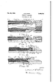
- FIG. 1 is a vertical section of one embodiment of the invention
- Figs.'2, 3 and 4 are partial vertical sections of other embodiments of the invention.
- the reference character indicates a nipple on which is mounted a connection nut 2.
- a connection nut 2 Spread over the end of the nipple opposite the nut 2 is a flexible hose or the like 3.
- the hose 3 is secured on the nipple by a ferrule 4.
- the grip between the hose 3 and the ferrule 4 is increased by the employment of the serrations 5 of a conventional nature.
- the ferrule 4 in the form of the invention disclosed in Fig. 1 is secured by threads 6 to the nipple I.
- the threaded relationship between the ferrule 4 and the nipple l is not an essential feature of the invention in its broadest aspects.
- sealing rings 9 and Ill Arranged in the cavity 1 are sealing rings 9 and Ill.
- the sealing rings 9 and Ill are disposed at opposite ends of the cavity 1, and are preferably of the type known as 0. They are generally of synthetic rubber and are of a suitable consistency to permit them to flex under pressure into sealing relation with the walls with which they are in contact.
- the cavity 1 is divided into two parts by a spacer l5, which is shown in Fig. 1 as being integral with the ferrule i.
- the spacer I5 does not quite reach the opposite side of the cavity 1, that is, it does not come into contact with the nipple i, so as to permit the equalization of fluid pressure within all parts of the cavity 'l.
- a port [6 is disposed in the nipple I providing communicationbetween the interior of the nipple l and the chamber "i. While only two ports it are shown, it will be understood that the number of ports I6 is not critical so long as fluid pressure communication between the interior of the nipple l and the cavity 7 is maintained.
- the pressure within the cavity 1 likewise forces the ring ll] to the right as viewed in Fig. 1 urging the same into sealing relation with the connection between the nipple i and the ferrule d.
- the spacer l5 serves to maintain the rings 9 and ill on opposite sides of the port l6.
- has disposed thereon a hose 42, or the like,
- FIG. 3 the hose or the like 42 being clamped to the nipple 4
- the structure of Fig. 2 is somewhat different from that disclosed in Fig. 1, in that there is provided between a portion of the nipple 4
- a port 49 provides communication between the interior of the nipple I 4
- the ferrule is secured to the nipple 4
- Fig. 2 The operation of the invention disclosed in Fig. 2 is such that fluid pressure from within the nipple 4
- is provided with an integral ferrule 52 which is formed into a clamping relation with the hose 53 in some suitable manner as by swaging.
- preferably is formed by swaging a tube 51' to a connector 52.
- is an annular wedge 54.
- the wedge 54 is provided with an annular foot portion 55 axially slidable in an annular cavity 56. A seal is maintained between the cylindrical walls of the cavity 56 by sealing rings 51 of the 0 type.
- One or more ports 58 are arranged in the nipple 5
- one or more ports 59 are provided in the ferrule 52 for providing communication between the atmosphere and the cavity 56.
- a washer 60 is provided in the cavity 56 adjacent the inner end of the hose 53 to limit the inner movement of the hose 53 due to its being squeezed by the nipple 5
- engages with the annular foot portion 55 to force the wedge 54 axially between the nipple 5
- the port 59 serves to permit the escape of air from the portion of the cavity 56 between the annular foot portion 55 and the washer 60 during axial movement ofthe wedge 54 under the action of fluid pressure from within the nipple 5
- FIG. 4 Another form of the invention is disclosed in Fig. 4 and is somewhat similar to the disclosure of Fig. 3 except that the wedge 6
- the ferrule 62 is arranged to be swaged onto the hose 63 and preferably is secured to the connector 65 as by brazing at the connection 66.
- the swaged portion 61 of the ferrule 62 should be sufficiently spaced from the end of the wedge 6
- is provided with a foot portion 68 similar to the foot portion 55 of Fig. 6.
- the foot portion 66 is arranged to slide in an annular cavity 69 and is provided with sealing rings 10 of the 0 type.
- provide communication between the interior of the nipple 64 and the cavity 69.
- a socket-nipple end fitting for flexible hose said hose having an end portion clamped between the nipple and socket, an annular cavity defined between said nipple and socket in axially adjacent relationship to the inner end of the clamped hose, port means through the wall of said cavity providing fluid flow communication between its interior and the nipple interior, a first sealing means in said cavity between said port means and said inner end of the hose, and a second sealing means between the socket and the nipple, said sealing means being adapted to be acted upon by the admitted fluid pressure to increase their sealing action.
- annular wedge slidable in said cavity between one wall of the latter and the clamped hose end, and an annular piston incorporated in one end of said annular wedge and operable in said annular cavity, both said sealing means being provided upon said annular position in position to effect their respective seals and said piston defining one end of said cavity.
Landscapes
- Engineering & Computer Science (AREA)
- General Engineering & Computer Science (AREA)
- Mechanical Engineering (AREA)
- Joints That Cut Off Fluids, And Hose Joints (AREA)
Description
Oct. 25, 1949. o. w. MAIN 2,485,976
HYDRAULIC CONNECTOR Filed llarch 8, 1946 Patented Oct. 25, 1949 2,485,976 HYDRAULIC CONNECTOR Donald W. Main, Jackson, Mich., assignor, by to Aeroquip Corporation,
mesne assignments, Jackson,
Mich, a corporation of Michigan Application March 8, 194.6, Serial No. 652,99d
3 Claims. (Cl. 285-84) I The present inventioii relates to connectors and more particularly to connectors wherein a hose or the like is clamped between a nipple and a ferrule.
The function of the ferrule in connectors of the character described is not only to hold the hose against separation from the nipple, but is also for preventing the leakage of fluid from within the hose between the nipple and the hose or the like. The present invention provides structure for increasing the effectiveness of the seal between the nipple and the ferrule. v
An object of the invention is to provide a leakproof seal between a nipple and hose.
Another object of the invention is to employ a resilient ring between the ferrule and nipple between which is disposed one end of a hose, sealing the connection against leakage.
Another object of the invention is to provide a sealing structure between the nipple aid the ferrule in a connector of the character described wherein the fluid pressure from within the nipple is employed to increase the effectiveness of the seal.
Still another object of the invention is to provide a pair of resilient rings between the nipple and ferrule of a connector of the character described wherein fluid from within the nipple is conducted to the space between the rings to increase the effectiveness of the sealing action afforded by the rings.
Still another object of the invention is to provide in a connector of the character described, an annular-wedge associated with an annular sealing ring subjected to pressure from within the nipple, to increase the effectiveness of the seal between the nipple and the hose disposed thereon.
These and other objects residing in the arrangement, combination, and construction of parts will be apparent from the following specification when taken with the accompanying drawings, in which Fig. 1 is a vertical section of one embodiment of the invention, and
Figs.'2, 3 and 4 are partial vertical sections of other embodiments of the invention.
Referring particularly to the drawings, the reference character indicates a nipple on which is mounted a connection nut 2. Spread over the end of the nipple opposite the nut 2 is a flexible hose or the like 3. The hose 3 is secured on the nipple by a ferrule 4. The grip between the hose 3 and the ferrule 4 is increased by the employment of the serrations 5 of a conventional nature. The ferrule 4 in the form of the invention disclosed in Fig. 1 is secured by threads 6 to the nipple I. However, the threaded relationship between the ferrule 4 and the nipple l is not an essential feature of the invention in its broadest aspects.
While the action of the ferrule 4 against the hose 3 is sufficient to retain it from separation from the nipple I, it is not suflicient in all cases to prevent the leakage of fluid from within the hose 3 between the hose 3 and the nipple I. It is in order to prevent this leakage that the present invention has been designed. Between the ferrule 4 and the nipple l is arranged a cavity 1 which has one end thereof defined by the end portion 8 of the hose. or the like, 3.
Arranged in the cavity 1 are sealing rings 9 and Ill. The sealing rings 9 and Ill are disposed at opposite ends of the cavity 1, and are preferably of the type known as 0. They are generally of synthetic rubber and are of a suitable consistency to permit them to flex under pressure into sealing relation with the walls with which they are in contact.
The cavity 1 is divided into two parts by a spacer l5, which is shown in Fig. 1 as being integral with the ferrule i. The spacer I5 does not quite reach the opposite side of the cavity 1, that is, it does not come into contact with the nipple i, so as to permit the equalization of fluid pressure within all parts of the cavity 'l. A port [6 is disposed in the nipple I providing communicationbetween the interior of the nipple l and the chamber "i. While only two ports it are shown, it will be understood that the number of ports I6 is not critical so long as fluid pressure communication between the interior of the nipple l and the cavity 7 is maintained.
In operation, fluid pressure within the nipple l passing through the ports it tends to force the sealing rings 9 and I0 outwardly as viewed in Fig. l. The sealing ring 9 bears against a steel washer ll, placed against the end of the hose 3 to distribute the force exerted by thering 9 over a larger area of the end 8 of the hose 3. The pressure against the ring 9 forces the ring 9 against the steel plate ll, the nipple l and the ferrule 4 to seal all openings through which communication might be established from the interior of the nipple l and hose 3 outwardly past the connection provided by the nipple I and the ferrule 4 with the hose 3. The pressure within the cavity 1 likewise forces the ring ll] to the right as viewed in Fig. 1 urging the same into sealing relation with the connection between the nipple i and the ferrule d. The spacer l5 serves to maintain the rings 9 and ill on opposite sides of the port l6.
It will be clear that the present invention greatly improves the seal over that provided by the usual nipple and ferrule connection with a hose, thereby permitting fluid of higher pressures to be carried by the hose 3. The structure disclosed in Fig. 1 constitutes one example of a form the invention may take. Other forms of the invention are shown by the other figures of the drawing.
Another form of the invent on is disclosed in Fig. 2. In this form of the'invention, a nipple 4| has disposed thereon a hose 42, or the like,
3 the hose or the like 42 being clamped to the nipple 4| by a ferrule 43. The structure of Fig. 2 is somewhat different from that disclosed in Fig. 1, in that there is provided between a portion of the nipple 4| and the hose 42, an annular wedge 44. Between the ferrule 43 and the nipple 4| is provided an annular cavity 45 which is similar to the other cavities hereinabove described with the exception, however, that between the sealing rings 46 and 41 therein, which are of the type, there is no spacer; the sealing'rings 46 and 41 being adjacent each other. A port 49 provides communication between the interior of the nipple I 4| and the cavity 45. The ferrule is secured to the nipple 4| by a threaded connection 50.
The operation of the invention disclosed in Fig. 2 is such that fluid pressure from within the nipple 4| passes through the port 49 into the cavity 45 to urge the sealing rings 46 and 41 apart. Sealing ring 46 is urged against the threaded connection 50 to seal the same against any passage of fluid while the sealing ring 41 bears against the wedge 44 to urge the same further into a wedging relation with the hose 42 and the nipple 4|, and at the same time provides an effective seal between the sides of the cavity 45 and the inner end of the wedge 44. It will be understood that in this form of the invention the additional stress imposed upon the annular wedge 44 by the pressure within the coupling and forcing it into further wedging relation between the hose 42 and the nipple 4| causes an effective seal between the nipple 4| and the hose 42 or the like.
Another form of the, invention is disclosed in Fig. 3 wherein a nipple 5| is provided with an integral ferrule 52 which is formed into a clamping relation with the hose 53 in some suitable manner as by swaging. The nipple 5| preferably is formed by swaging a tube 51' to a connector 52. Disposed around the nipple 5| is an annular wedge 54. The wedge 54 is provided with an annular foot portion 55 axially slidable in an annular cavity 56. A seal is maintained between the cylindrical walls of the cavity 56 by sealing rings 51 of the 0 type. One or more ports 58 are arranged in the nipple 5| for providing communication between the interior of the nipple 5| and the cavity 56. Also, one or more ports 59 are provided in the ferrule 52 for providing communication between the atmosphere and the cavity 56. A washer 60 is provided in the cavity 56 adjacent the inner end of the hose 53 to limit the inner movement of the hose 53 due to its being squeezed by the nipple 5| and the ferrule 52.
In the operation of the form of the invention disclosed in Fig. 3, fluid pressure from within the nipple 5| engages with the annular foot portion 55 to force the wedge 54 axially between the nipple 5| and the ferrule 52 to increase the radial pressure against the portion of the hose 53 within the ferrule 52.- The port 59 serves to permit the escape of air from the portion of the cavity 56 between the annular foot portion 55 and the washer 60 during axial movement ofthe wedge 54 under the action of fluid pressure from within the nipple 5|.
Another form of the invention is disclosed in Fig. 4 and is somewhat similar to the disclosure of Fig. 3 except that the wedge 6| therein extends between the ferrule 62 and the hose 63 rather than between the nipple 64 and the hose 63. In Fig. 4 the ferrule 62 is arranged to be swaged onto the hose 63 and preferably is secured to the connector 65 as by brazing at the connection 66. The swaged portion 61 of the ferrule 62 should be sufficiently spaced from the end of the wedge 6| so as to provide a cylindrical portion within which the wedge 6| may act.
The wedge 6| is provided with a foot portion 68 similar to the foot portion 55 of Fig. 6. The foot portion 66 is arranged to slide in an annular cavity 69 and is provided with sealing rings 10 of the 0 type. Port or ports 1| provide communication between the interior of the nipple 64 and the cavity 69.
The operation of the form of the invention disclosed in Fig. 4 is similarto that disclosed in Fig. 3 in that pressure from within the nipple 64 urges the wedge 6| axially to increase the pressure on the hose 63 between the ferrule 62 and the nipple 64. It will be understood that the wedges in the forms of the invention disclosed in both Figs. 3 and 4 are inserted in their respective ferrules prior to the ferrules being swaged.
The various forms of the invention which have been disclosed illustrate various specific forms which the invention may take. It will be apparent that there may be other specific forms which the invention may take which have not been disclosed herein. The reference to a hose includes tubing and other like articles of any suitable composition which are adaptable for use with the invention.
Having thus described my invention, what I desire to secure by Letters Patent and claim is:
1. In a socket-nipple end fitting for flexible hose, said hose having an end portion clamped between the nipple and socket, an annular cavity defined between said nipple and socket in axially adjacent relationship to the inner end of the clamped hose, port means through the wall of said cavity providing fluid flow communication between its interior and the nipple interior, a first sealing means in said cavity between said port means and said inner end of the hose, and a second sealing means between the socket and the nipple, said sealing means being adapted to be acted upon by the admitted fluid pressure to increase their sealing action.
2. In a socket-nipple end fitting as defined in claim 1. an annular wedge slidable in said cavity between one wall of the latter and said clamped hose end, said first sealing means operating against said wedge to increase its grip on the hose end.
3. In a socket-nipple end fitting as defined-in claim 1, an annular wedge slidable in said cavity between one wall of the latter and the clamped hose end, and an annular piston incorporated in one end of said annular wedge and operable in said annular cavity, both said sealing means being provided upon said annular position in position to effect their respective seals and said piston defining one end of said cavity.
- DONALD W. MAIN.
REFERENCES CITED The following references are of record in the file of this patent:
UNITED STATES PATENTS 582,326 France June 4, 1924
Priority Applications (1)
| Application Number | Priority Date | Filing Date | Title |
|---|---|---|---|
| US652996A US2485976A (en) | 1946-03-08 | 1946-03-08 | Hydraulic connector |
Applications Claiming Priority (1)
| Application Number | Priority Date | Filing Date | Title |
|---|---|---|---|
| US652996A US2485976A (en) | 1946-03-08 | 1946-03-08 | Hydraulic connector |
Publications (1)
| Publication Number | Publication Date |
|---|---|
| US2485976A true US2485976A (en) | 1949-10-25 |
Family
ID=24619070
Family Applications (1)
| Application Number | Title | Priority Date | Filing Date |
|---|---|---|---|
| US652996A Expired - Lifetime US2485976A (en) | 1946-03-08 | 1946-03-08 | Hydraulic connector |
Country Status (1)
| Country | Link |
|---|---|
| US (1) | US2485976A (en) |
Cited By (45)
| Publication number | Priority date | Publication date | Assignee | Title |
|---|---|---|---|---|
| US2517606A (en) * | 1948-11-24 | 1950-08-08 | Scovill Manufacturing Co | Hose coupling |
| US2676037A (en) * | 1948-06-09 | 1954-04-20 | Mueller Otto | High-pressure fluid connector |
| US2716542A (en) * | 1952-01-23 | 1955-08-30 | Oilwell Drain Hole Drilling Co | Flexible drill collars |
| US2768009A (en) * | 1953-01-23 | 1956-10-23 | Parker Appliance Co | Coupling with recess for end of flexible pipe |
| US2809056A (en) * | 1950-12-11 | 1957-10-08 | Aeroquip Corp | Plural layer hose fitting having wedge gripping means for the plural layers |
| US2850302A (en) * | 1953-09-16 | 1958-09-02 | Stratoflex Inc | Hose coupling with ribbed socket |
| US2862731A (en) * | 1955-04-29 | 1958-12-02 | Chiksan Co | Flanged, bend-clamped swivel coupling for fluid handling tubes |
| DE1068069B (en) * | 1959-10-29 | |||
| US2940778A (en) * | 1956-04-25 | 1960-06-14 | Kaiser Rudolf | Fitting for a large-diameter rubber or plastic hose subjected to high loads |
| DE1093151B (en) * | 1958-07-24 | 1960-11-17 | Neue Argus Gmbh | Easily detachable hose connection |
| US2967067A (en) * | 1956-03-09 | 1961-01-03 | Interowa Furer Haimendorf Komm | Joint for pipes and tubes |
| DE1098301B (en) * | 1956-04-25 | 1961-01-26 | Neue Argus Gmbh | Automatically resealing hose screw connection for rubber or plastic hoses |
| US3032358A (en) * | 1960-03-04 | 1962-05-01 | Kenneth P Rolston | Hose coupling |
| US3051511A (en) * | 1958-07-14 | 1962-08-28 | Thomas L Fawick | Hose coupling having fluid pressure balancing means |
| US3097866A (en) * | 1960-11-14 | 1963-07-16 | Weatherhead Co | Pressurized hose end |
| US3124040A (en) * | 1964-03-10 | Support system for tube launched | ||
| US3160426A (en) * | 1961-03-13 | 1964-12-08 | Aerojet General Co | Pipe coupling having secondary resilient seal means |
| US3222091A (en) * | 1962-08-30 | 1965-12-07 | Dixon Valve & Coupling Co | Pressure responsive fluid tight hose coupling |
| DE1247775B (en) * | 1963-01-21 | 1967-08-17 | Esref I Halilovic | Hose coupling for hoses for guiding a fluid under high pressure |
| US3409314A (en) * | 1966-05-27 | 1968-11-05 | Homer D. Roe | Pipe couplings |
| US3490793A (en) * | 1968-08-16 | 1970-01-20 | John B Wagner | Coupling for a hose |
| JPS54140318U (en) * | 1978-03-23 | 1979-09-29 | ||
| JPS5748384U (en) * | 1980-09-02 | 1982-03-18 | ||
| US4394787A (en) * | 1978-07-27 | 1983-07-26 | Dorma Door Controls Inc. | Hydraulic door closer construction |
| JPS60500096A (en) * | 1982-12-30 | 1985-01-24 | コ−ルダ− プロダクツ カンパニ− | Attachment for soft tube |
| US4688830A (en) * | 1986-06-09 | 1987-08-25 | Fastest, Inc. | Externally threaded quick connect coupling having integral fluid pressure assisted seal |
| US4775171A (en) * | 1987-04-06 | 1988-10-04 | Marshall Don J | High pressure field repair coupling |
| US4830409A (en) * | 1987-01-14 | 1989-05-16 | Freeman John F | Composite pipe coupling |
| US4863197A (en) * | 1988-03-03 | 1989-09-05 | Ingersol-Rand Company | High-pressure end fitting |
| FR2628178A1 (en) * | 1988-03-03 | 1989-09-08 | Ingersoll Rand Co | TIP FOR HIGH PRESSURE FLEXIBLE PIPING |
| US4884830A (en) * | 1988-01-19 | 1989-12-05 | Fastest, Inc. | Quick connect coupling device |
| DE3909899A1 (en) * | 1989-03-25 | 1990-09-27 | Continental Ag | Hose-connection fitting for a pressure hose |
| US5370425A (en) * | 1993-08-25 | 1994-12-06 | S&H Fabricating And Engineering, Inc. | Tube-to-hose coupling (spin-sert) and method of making same |
| US5417461A (en) * | 1993-08-25 | 1995-05-23 | S&H Fabricating And Engineering, Inc. | Tube-to-hose coupling (crimp-sert) and method of making same |
| US5653475A (en) * | 1993-06-08 | 1997-08-05 | Kuehner Gmbh & Cie | Collant coupling for connecting coolant lines |
| WO1998058204A1 (en) * | 1997-06-19 | 1998-12-23 | Manuli Auto France | Device for sealed connection between a metal tube joining piece and a flexible pipe, and method for making same |
| US5961157A (en) * | 1995-07-24 | 1999-10-05 | Manuli Auto France | Device forming a leak-proof connection between a rigid tube end and a flexible pipe, and method for making same |
| US6439620B1 (en) * | 1998-11-24 | 2002-08-27 | John Derek Guest | Tube support |
| ES2192927A1 (en) * | 2001-03-27 | 2003-10-16 | Saneper S A | Pipe connection system and method for mounting such a system |
| US6769721B2 (en) * | 2000-01-24 | 2004-08-03 | John Quest International Limited | Molded plastics tubular couplings |
| EP1602870A1 (en) * | 2004-06-02 | 2005-12-07 | T I Group Automotive Systems, L.L.C. | Tube to hose coupling |
| US20060028020A1 (en) * | 2003-11-07 | 2006-02-09 | Wolfgang Fullbeck | Fitting for a sanitary hose |
| US20100207387A1 (en) * | 2009-02-18 | 2010-08-19 | Parker-Hannifin Corporation | Hose fitting |
| US20110148099A1 (en) * | 2009-12-18 | 2011-06-23 | E.I. Du Pont De Nemours And Company | Low stress hose coupling |
| US20120007356A1 (en) * | 2010-07-06 | 2012-01-12 | Caterpillar, Inc. | No-Skive Hydraulic Hose Coupling with Improved Hose Retention and Sealing |
Citations (2)
| Publication number | Priority date | Publication date | Assignee | Title |
|---|---|---|---|---|
| FR582326A (en) * | 1924-06-04 | 1924-12-16 | Flexible hose coupling | |
| US2373280A (en) * | 1943-07-06 | 1945-04-10 | Phillips Petroleum Co | Nonthrusting pipe expansion joint |
-
1946
- 1946-03-08 US US652996A patent/US2485976A/en not_active Expired - Lifetime
Patent Citations (2)
| Publication number | Priority date | Publication date | Assignee | Title |
|---|---|---|---|---|
| FR582326A (en) * | 1924-06-04 | 1924-12-16 | Flexible hose coupling | |
| US2373280A (en) * | 1943-07-06 | 1945-04-10 | Phillips Petroleum Co | Nonthrusting pipe expansion joint |
Cited By (54)
| Publication number | Priority date | Publication date | Assignee | Title |
|---|---|---|---|---|
| US3124040A (en) * | 1964-03-10 | Support system for tube launched | ||
| DE1068069B (en) * | 1959-10-29 | |||
| US2676037A (en) * | 1948-06-09 | 1954-04-20 | Mueller Otto | High-pressure fluid connector |
| US2517606A (en) * | 1948-11-24 | 1950-08-08 | Scovill Manufacturing Co | Hose coupling |
| US2809056A (en) * | 1950-12-11 | 1957-10-08 | Aeroquip Corp | Plural layer hose fitting having wedge gripping means for the plural layers |
| US2716542A (en) * | 1952-01-23 | 1955-08-30 | Oilwell Drain Hole Drilling Co | Flexible drill collars |
| US2768009A (en) * | 1953-01-23 | 1956-10-23 | Parker Appliance Co | Coupling with recess for end of flexible pipe |
| US2850302A (en) * | 1953-09-16 | 1958-09-02 | Stratoflex Inc | Hose coupling with ribbed socket |
| US2862731A (en) * | 1955-04-29 | 1958-12-02 | Chiksan Co | Flanged, bend-clamped swivel coupling for fluid handling tubes |
| US2967067A (en) * | 1956-03-09 | 1961-01-03 | Interowa Furer Haimendorf Komm | Joint for pipes and tubes |
| DE1098301B (en) * | 1956-04-25 | 1961-01-26 | Neue Argus Gmbh | Automatically resealing hose screw connection for rubber or plastic hoses |
| US2940778A (en) * | 1956-04-25 | 1960-06-14 | Kaiser Rudolf | Fitting for a large-diameter rubber or plastic hose subjected to high loads |
| US3051511A (en) * | 1958-07-14 | 1962-08-28 | Thomas L Fawick | Hose coupling having fluid pressure balancing means |
| DE1093151B (en) * | 1958-07-24 | 1960-11-17 | Neue Argus Gmbh | Easily detachable hose connection |
| US3032358A (en) * | 1960-03-04 | 1962-05-01 | Kenneth P Rolston | Hose coupling |
| US3097866A (en) * | 1960-11-14 | 1963-07-16 | Weatherhead Co | Pressurized hose end |
| US3160426A (en) * | 1961-03-13 | 1964-12-08 | Aerojet General Co | Pipe coupling having secondary resilient seal means |
| US3222091A (en) * | 1962-08-30 | 1965-12-07 | Dixon Valve & Coupling Co | Pressure responsive fluid tight hose coupling |
| DE1247775B (en) * | 1963-01-21 | 1967-08-17 | Esref I Halilovic | Hose coupling for hoses for guiding a fluid under high pressure |
| US3409314A (en) * | 1966-05-27 | 1968-11-05 | Homer D. Roe | Pipe couplings |
| US3490793A (en) * | 1968-08-16 | 1970-01-20 | John B Wagner | Coupling for a hose |
| JPS54140318U (en) * | 1978-03-23 | 1979-09-29 | ||
| US4394787A (en) * | 1978-07-27 | 1983-07-26 | Dorma Door Controls Inc. | Hydraulic door closer construction |
| JPS5748384U (en) * | 1980-09-02 | 1982-03-18 | ||
| JPS60500096A (en) * | 1982-12-30 | 1985-01-24 | コ−ルダ− プロダクツ カンパニ− | Attachment for soft tube |
| WO1987007698A1 (en) * | 1986-06-09 | 1987-12-17 | Fastest, Inc. | Externally threaded quick connect coupling having integral fluid pressure assisted seal and method of using same |
| US4688830A (en) * | 1986-06-09 | 1987-08-25 | Fastest, Inc. | Externally threaded quick connect coupling having integral fluid pressure assisted seal |
| US4830409A (en) * | 1987-01-14 | 1989-05-16 | Freeman John F | Composite pipe coupling |
| US4775171A (en) * | 1987-04-06 | 1988-10-04 | Marshall Don J | High pressure field repair coupling |
| US4884830A (en) * | 1988-01-19 | 1989-12-05 | Fastest, Inc. | Quick connect coupling device |
| US4863197A (en) * | 1988-03-03 | 1989-09-05 | Ingersol-Rand Company | High-pressure end fitting |
| FR2628178A1 (en) * | 1988-03-03 | 1989-09-08 | Ingersoll Rand Co | TIP FOR HIGH PRESSURE FLEXIBLE PIPING |
| DE3909899A1 (en) * | 1989-03-25 | 1990-09-27 | Continental Ag | Hose-connection fitting for a pressure hose |
| US5653475A (en) * | 1993-06-08 | 1997-08-05 | Kuehner Gmbh & Cie | Collant coupling for connecting coolant lines |
| US5370425A (en) * | 1993-08-25 | 1994-12-06 | S&H Fabricating And Engineering, Inc. | Tube-to-hose coupling (spin-sert) and method of making same |
| US5417461A (en) * | 1993-08-25 | 1995-05-23 | S&H Fabricating And Engineering, Inc. | Tube-to-hose coupling (crimp-sert) and method of making same |
| US5961157A (en) * | 1995-07-24 | 1999-10-05 | Manuli Auto France | Device forming a leak-proof connection between a rigid tube end and a flexible pipe, and method for making same |
| WO1998058204A1 (en) * | 1997-06-19 | 1998-12-23 | Manuli Auto France | Device for sealed connection between a metal tube joining piece and a flexible pipe, and method for making same |
| FR2764960A1 (en) * | 1997-06-19 | 1998-12-24 | Manuli Auto France | SEALED CONNECTION DEVICE BETWEEN A METAL TUBE BIT AND THE END OF A FLEXIBLE PIPE, AND METHOD OF MANUFACTURING SUCH A DEVICE |
| US6439620B1 (en) * | 1998-11-24 | 2002-08-27 | John Derek Guest | Tube support |
| US6769721B2 (en) * | 2000-01-24 | 2004-08-03 | John Quest International Limited | Molded plastics tubular couplings |
| ES2192927A1 (en) * | 2001-03-27 | 2003-10-16 | Saneper S A | Pipe connection system and method for mounting such a system |
| ES2192927B1 (en) * | 2001-03-27 | 2005-03-01 | Saneper, S.A. | SEALING GASKET DEVICE FOR TUBE UNIONS. |
| US20060028020A1 (en) * | 2003-11-07 | 2006-02-09 | Wolfgang Fullbeck | Fitting for a sanitary hose |
| US7380837B2 (en) * | 2003-11-07 | 2008-06-03 | Fullbeck Wolfgang F | Fitting for a sanitary hose |
| EP1602870A1 (en) * | 2004-06-02 | 2005-12-07 | T I Group Automotive Systems, L.L.C. | Tube to hose coupling |
| US20050285392A1 (en) * | 2004-06-02 | 2005-12-29 | Ray Brauckmiller | Tube to hose coupling |
| US20100207387A1 (en) * | 2009-02-18 | 2010-08-19 | Parker-Hannifin Corporation | Hose fitting |
| US8888140B2 (en) * | 2009-02-18 | 2014-11-18 | Parker-Hannifin Corporation | Hose fitting |
| US20110148099A1 (en) * | 2009-12-18 | 2011-06-23 | E.I. Du Pont De Nemours And Company | Low stress hose coupling |
| US20120007356A1 (en) * | 2010-07-06 | 2012-01-12 | Caterpillar, Inc. | No-Skive Hydraulic Hose Coupling with Improved Hose Retention and Sealing |
| CN102971568A (en) * | 2010-07-06 | 2013-03-13 | 卡特彼勒公司 | Non-cutting hydraulic hose coupling with improved hose retention and sealing |
| US9217527B2 (en) * | 2010-07-06 | 2015-12-22 | Caterpillar Inc. | No-skive hydraulic hose coupling with improved hose retention and sealing |
| CN102971568B (en) * | 2010-07-06 | 2016-01-20 | 卡特彼勒公司 | Non-cutting hydraulic hose coupling with improved hose retention and sealing |
Similar Documents
| Publication | Publication Date | Title |
|---|---|---|
| US2485976A (en) | Hydraulic connector | |
| US2441344A (en) | Coupling | |
| US2819099A (en) | Flange union fitting with contractible lined wedge | |
| US2896663A (en) | Check valve with valve seat of resilient material | |
| US2465197A (en) | Coupling | |
| US2453391A (en) | Tubing connection | |
| US3186740A (en) | Couplings for connecting tubular conduits | |
| US2453813A (en) | Coupling | |
| US2381829A (en) | Tube coupling | |
| US2421228A (en) | Hose coupling | |
| US4165106A (en) | Hose or pipe coupling | |
| US2008650A (en) | Hose coupling | |
| ES339311A1 (en) | JOINT SLEEVE DEVICE FOR PRESSURE PIPES, ESPECIALLY FOR BRAKES AND HYDRAULIC CLUTCHES. | |
| US4189162A (en) | Hydraulic chuck | |
| US2436206A (en) | Self-sealing coupling | |
| US3592231A (en) | Quick connect couplings with selective connection means | |
| US2319586A (en) | End fitting for flexible hoses | |
| US3781040A (en) | Pipe joint seal | |
| US2754847A (en) | Piston-type accumulators | |
| US2391022A (en) | Self-sealing coupling | |
| US3971577A (en) | Union device for flexible tubing | |
| US2438530A (en) | Coupling member | |
| US2443145A (en) | Coupling | |
| GB1482197A (en) | Couplings for units such as pipes and the like | |
| US2661967A (en) | Fluid seal |