US248564A - rhetjtan - Google Patents
rhetjtan Download PDFInfo
- Publication number
- US248564A US248564A US248564DA US248564A US 248564 A US248564 A US 248564A US 248564D A US248564D A US 248564DA US 248564 A US248564 A US 248564A
- Authority
- US
- United States
- Prior art keywords
- envelopes
- machine
- plates
- envelope
- secured
- Prior art date
- Legal status (The legal status is an assumption and is not a legal conclusion. Google has not performed a legal analysis and makes no representation as to the accuracy of the status listed.)
- Expired - Lifetime
Links
- 230000000717 retained effect Effects 0.000 description 2
- 241000735495 Erica <angiosperm> Species 0.000 description 1
- 230000000284 resting effect Effects 0.000 description 1
Images
Classifications
-
- B—PERFORMING OPERATIONS; TRANSPORTING
- B31—MAKING ARTICLES OF PAPER, CARDBOARD OR MATERIAL WORKED IN A MANNER ANALOGOUS TO PAPER; WORKING PAPER, CARDBOARD OR MATERIAL WORKED IN A MANNER ANALOGOUS TO PAPER
- B31B—MAKING CONTAINERS OF PAPER, CARDBOARD OR MATERIAL WORKED IN A MANNER ANALOGOUS TO PAPER
- B31B50/00—Making rigid or semi-rigid containers, e.g. boxes or cartons
-
- B—PERFORMING OPERATIONS; TRANSPORTING
- B31—MAKING ARTICLES OF PAPER, CARDBOARD OR MATERIAL WORKED IN A MANNER ANALOGOUS TO PAPER; WORKING PAPER, CARDBOARD OR MATERIAL WORKED IN A MANNER ANALOGOUS TO PAPER
- B31B—MAKING CONTAINERS OF PAPER, CARDBOARD OR MATERIAL WORKED IN A MANNER ANALOGOUS TO PAPER
- B31B70/00—Making flexible containers, e.g. envelopes or bags
- B31B70/006—Controlling; Regulating; Measuring; Safety measures
Definitions
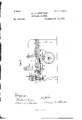
- FIG. 2 represents an end view of the machine shown in Fig. l, looking in the direction indicated by arrow l', same figure and Fig. 3 represents a vertical longitudinal section through the machine, taken on line A B, Fig. l, looking in the direction indicated by arrow 2', same ligure.
- My invention relates to that part of the mechanism of an envelope-counting machine used for the purpose of placing the envelopes in distinct packages after they are folded and delivered to the counting-machine, and is designed to be used upon any envelopefolding machine.
- part marked a represents the bed or bottom of the box, which can be attached to the frame of an envelope-folding machine in any suitable manner. In this instance it is represented as being supported upon legs or standards b at each corner ofthe same.
- Plates n n are formed or secured upon the upper ends of vertically-arranged bars p p, which in turn are secured to sliding shaftf.
- the outer end of lever h is in this instance passed through a slot formed in the enlarged portion q of sliding shaftf, although any other suit-able connection may be employed, if desired.
- Roll o is tted to turn upon a stud formed or secured upon the lower side of lever h, and is arranged between the cam-wheels m m', thereby imparting an alternate' lateral motion to shaft f and its top plates, u a, when said cam-wheels are in operation, by each cam being cut away upon the inner side half-way around the same, and arranging them ⁇ in reversed positions, as represented in Fig. 2 of the drawings.
- top plates, n n Upon the top of bed a are secured side pieces, r o", which form the sides of the boX, and through these side pieces are cut grooved ways s s, in which guide t(to which the pusher-plate u is secured) moves back and forth. Grooves or slots e are also formed in said side pieces to allow the top plates, n n, to pass through when operated. Said top plates, an, are secured at their outer edges to upright supports p p, and are inclined downward slightly toward the inside of the machine.
- tops of said ways w w are arranged to come upon a line, or nearly so, with the tops of plates n n, so that the envelopes may readily slide along from the surfaces of the latter to those of the former, when pushed forward by the guide and pusherplate t u.
- Rocking shaft k is provided with projecting arms or fingers a: w ar, which extend up through and above bed a, for the purpose of retaining the envelopes in position as they are fed into the machine, and moved forward by the pusherplate.
- crank-arm Upon the under side of the center finger, m', and extending downward, is formed or secured a crank-arm, a, by means of which and spring y the fingers are sprung back when pushed forward by the envelopes, as hereinafter described.
- the pusher-,plate u is cutout upon its under side to allow it to pass over the ways w w, and by the fingers w w av, without moving the latter when there is no envelope in front of the pusher-plate.
- the guide and pusher-plate t u are connected through sui table mechanism with the main shaft of the envelope-folding machine, and have imparted to them aforward and backward movement with each revolution of said shaft of the folding-machine.
- the envelopes after being completed in the folding-machine, are conducted through suitable guideways or feeding mechanism, and delivered :in a vertical position in front of and between the pusherplate u and fingers w w, one end of the envelopes resting upon the bed of the box, while the other end rests upon one of the plates u, which has previously been moved forward to receive them.
- crankarm m2 Any suitable and convenient mechanism may be used for connecting crankarm m2 with the ratchet-wheel l, whereby the movement imparted to said crank-arm, through the iin gers .z' w a', rocking shaft 7c, slide and pusher-plato t u, and the envelopes, would cause the ratchet-wheel l to move one notch for each and every envelope moved forward by said slide and pusher-plate.
- the number ofenvelopes to a package is governed by the number ol' teeth in ratchet-wheel l.
- the usual number being twenty-tive, the ratchet-wheel will therefore be provided, as in this instance, with fty teeth, as the positions of the envelopes are changed at each half-revolution of said ratchet -wheel l, by cams m m being arranged in reversed positions, as before stated, and shown in Fig'. 2 ofthe drawings.
- Lines 7 and 8, Fig. 2 represent the inclined positions of the envelopes after they have been pushed by the stops 3, 4, and 5, as before described.
- y 1 In an envelope-countingmachine,laterally moving plates n n, arranged and operating substantially as and for the purposes set forth.
Landscapes
- Folding Of Thin Sheet-Like Materials, Special Discharging Devices, And Others (AREA)
Description
(No Model.)
A. A. RHEUTAN.
ElwLLmeF MACHINE;
llLVlEEEEE,
y l Patented Get. 18,1881. lzlgpl.
4 2 Sheets-Shet l.
2 Sheets-Sl-eet 2.
(No Model.)
A. A. RHEUTAN.
BNVELOPB MACHINE.
No. 248,564. Patented 0ot.-18, 1881.
ITP/5111011,
NITED 'STATES 'PATENT erica ABBA A. RHEUTAN, OF l/VOHGESTER, MASSACHUSETTS, ASSIGNOR TO WADE H. HILL, OF SAME PLACE.
ENvELoPEMAcHINE.
SPECIFICATION forming part of Letters PatentvNo. 248,564, dated October 18, 1881,
Application filed June 6, 1881. (No model.)
To all whom it may concern Be .it known that I, ABRAM A. RHEUTAN,
. of the cit-y and county of Worcester, and State of Massachusetts, have invented certain new and useful 1m provements in Envelope-Counting Machines; and I do hereby declare that the following is a full, clear, and exact description of the same, reference being had to the accompanying drawings,forining a part of this specification, and in which- Figure l represents a top or plan view of so much of an envelopecounting machine as is necessary to illustrate my present invention. Fig. 2 represents an end view of the machine shown in Fig. l, looking in the direction indicated by arrow l', same figure and Fig. 3 represents a vertical longitudinal section through the machine, taken on line A B, Fig. l, looking in the direction indicated by arrow 2', same ligure.
My invention relates to that part of the mechanism of an envelope-counting machine used for the purpose of placing the envelopes in distinct packages after they are folded and delivered to the counting-machine, and is designed to be used upon any envelopefolding machine.
It consists of the ordinary box or trough into which the envelopes are delivered, with two horizontally-sliding plates arranged at each side of the rear end of the same upon a horizontal sliding shaft, for the purpose of giving to each alternate package of envelopes opposite inclined positions. It also consists in the mechanism employed for operating the aforesaid plates, as will be hereinafter more fully set forth.
To enable those skilled in the art to which myinventiou belongs to make and usethe same, I will proceed to describe it more in detail.
In the drawings, the part marked a represents the bed or bottom of the box, which can be attached to the frame of an envelope-folding machine in any suitable manner. In this instance it is represented as being supported upon legs or standards b at each corner ofthe same.
To the bottom of bed a are secured the following parts: large hangers c c, upon which the main shaft d is hung, being arranged to Upon the main shaft d are secured the ratchet or counting wheel Zand cam-wheelsm m', which latter operate thesliding shaftf and its top plates, n, laterally by means of oscillating lever 7L and roll 0. I
Plates n n are formed or secured upon the upper ends of vertically-arranged bars p p, which in turn are secured to sliding shaftf. The outer end of lever h is in this instance passed through a slot formed in the enlarged portion q of sliding shaftf, although any other suit-able connection may be employed, if desired.
Roll o is tted to turn upon a stud formed or secured upon the lower side of lever h, and is arranged between the cam-wheels m m', thereby imparting an alternate' lateral motion to shaft f and its top plates, u a, when said cam-wheels are in operation, by each cam being cut away upon the inner side half-way around the same, and arranging them `in reversed positions, as represented in Fig. 2 of the drawings.
Upon the top of bed a are secured side pieces, r o", which form the sides of the boX, and through these side pieces are cut grooved ways s s, in which guide t(to which the pusher-plate u is secured) moves back and forth. Grooves or slots e are also formed in said side pieces to allow the top plates, n n, to pass through when operated. Said top plates, an, are secured at their outer edges to upright supports p p, and are inclined downward slightly toward the inside of the machine. They are of sufcient width to extend in beyond the inner surface of side pieces, r r, one-half inch, more or less, when the inner edges of upright bars p p are brought in contact with or nearly to the outer edges of said side pie/cesn'r, and their lengths are from the reartends of the side pieces to nearly over rocking shaft k. If preferred, i11- stead of the top plates, n a, being formed or se- IOO Upon the inner sides of side pieces, r r, nearthe bottom, are secured ways zo w, which extend from the ends of plates n n forward the. full length of said side pieces, and projecting in toward the center of the box one-half inch# more or less, as desired. The tops of said ways w w are arranged to come upon a line, or nearly so, with the tops of plates n n, so that the envelopes may readily slide along from the surfaces of the latter to those of the former, when pushed forward by the guide and pusherplate t u.
Rocking shaft k is provided with projecting arms or fingers a: w ar, which extend up through and above bed a, for the purpose of retaining the envelopes in position as they are fed into the machine, and moved forward by the pusherplate.
Upon the under side of the center finger, m', and extending downward, is formed or secured a crank-arm, a, by means of which and spring y the fingers are sprung back when pushed forward by the envelopes, as hereinafter described.
The pusher-,plate uis cutout upon its under side to allow it to pass over the ways w w, and by the fingers w w av, without moving the latter when there is no envelope in front of the pusher-plate.
Operation: The guide and pusher-plate t u are connected through sui table mechanism with the main shaft of the envelope-folding machine, and have imparted to them aforward and backward movement with each revolution of said shaft of the folding-machine. The envelopes, after being completed in the folding-machine, are conducted through suitable guideways or feeding mechanism, and delivered :in a vertical position in front of and between the pusherplate u and fingers w w, one end of the envelopes resting upon the bed of the box, while the other end rests upon one of the plates u, which has previously been moved forward to receive them. The envelopes are then pushed forward bythe forward movement ofthe slide and pusherfplate t u, and brought in contact with the fingers x x, which are consequently forced forward and down, causing rocking shaft le to turn part way around in its bearings. By the partial turning of rocking shaft k, as above described, motion is imparted to crank-arm av upon the center iin ger, and ratchet or counting wheel l is turned one notch or tooth forward.
Any suitable and convenient mechanism may be used for connecting crankarm m2 with the ratchet-wheel l, whereby the movement imparted to said crank-arm, through the iin gers .z' w a', rocking shaft 7c, slide and pusher-plato t u, and the envelopes, would cause the ratchet-wheel l to move one notch for each and every envelope moved forward by said slide and pusher-plate. As thc envelopes are moved forward by the slide and pusher-plate, they are carried past the circle described by the fingers x w, and beyond the stops 3 4 5, arranged on the ways w fw, bed a, and cross-bar 6, which prevent the eu- -velopes from returning or fallingback when the pusher-plate moves back. The envelopes being held by said stops, the fingers a: w' :v are thereby enabled to return and assume their upright positions, ready for the next envelope. The envelopes are retained in their upright positions after passing stops 3 4 5 by means of the usual sliding weight, z,which slides back as fast as the envelopes are moved forward past said stops.
The number ofenvelopes to a package is governed by the number ol' teeth in ratchet-wheel l. The usual number being twenty-tive, the ratchet-wheel will therefore be provided, as in this instance, with fty teeth, as the positions of the envelopes are changed at each half-revolution of said ratchet -wheel l, by cams m m being arranged in reversed positions, as before stated, and shown in Fig'. 2 ofthe drawings.
As the envelopes are moved forward ott' of plates u n, they are retained in their inclined positions by means ot' the ways w w, one end of each alternate package being supported up on the opposite way to that upon which the others are supported, while their opposite ends restupon the bed of the box near the way,and are so held in position to the full extent of the box, or until removed by the operator.
Having described my improvements in envelope-counting machines, whatI claim therein as new and of. my invention, and desire to secure by Letters Patent, is-
y 1. In an envelope-countingmachine,laterally moving plates n n, arranged and operating substantially as and for the purposes set forth.
2. 1n an envelope-cou ntin g machine, the combination of plates n n, their vertical support ing-armspp, and sliding shaftf, substantially as and for the purposes set forth.
ABRAM A. RHEUTAN.
Witnesses WALTER B. NoURsE,
ALBERT A. BAKKER.
IOO
IIO
Publications (1)
| Publication Number | Publication Date |
|---|---|
| US248564A true US248564A (en) | 1881-10-18 |
Family
ID=2317883
Family Applications (1)
| Application Number | Title | Priority Date | Filing Date |
|---|---|---|---|
| US248564D Expired - Lifetime US248564A (en) | rhetjtan |
Country Status (1)
| Country | Link |
|---|---|
| US (1) | US248564A (en) |
Cited By (1)
| Publication number | Priority date | Publication date | Assignee | Title |
|---|---|---|---|---|
| US2920888A (en) * | 1956-09-27 | 1960-01-12 | Halverson Products Mfg Company | Collecting mechanism for collating machine |
-
0
- US US248564D patent/US248564A/en not_active Expired - Lifetime
Cited By (1)
| Publication number | Priority date | Publication date | Assignee | Title |
|---|---|---|---|---|
| US2920888A (en) * | 1956-09-27 | 1960-01-12 | Halverson Products Mfg Company | Collecting mechanism for collating machine |
Similar Documents
| Publication | Publication Date | Title |
|---|---|---|
| US248564A (en) | rhetjtan | |
| US244485A (en) | rheutan | |
| US399987A (en) | Paper-folding machine | |
| US748428A (en) | Pasting-machine. | |
| US162341A (en) | Improvement in feeding mechanisms for paper-box machines | |
| US420792A (en) | Machine for making and printing envelopes | |
| US492116A (en) | Cloth-folding machine | |
| US557500A (en) | Plaiting-machine | |
| US151158A (en) | Improvement in machines for counting and packing envelopes | |
| US974648A (en) | Counter and stacker. | |
| US521153A (en) | Envelope-machine | |
| US452325A (en) | Envelope-machine | |
| US948920A (en) | Paper-folding machine. | |
| US1040201A (en) | Wrapping-machine. | |
| US302558A (en) | Paper-folding machine | |
| US141862A (en) | Improvement in machines for making paper bags | |
| US551918A (en) | Machine | |
| US408200A (en) | Envelope-machine | |
| US784209A (en) | Wire-fence machine. | |
| US2108157A (en) | Means fok | |
| US504136A (en) | Half to the w | |
| US205301A (en) | Improvement in newspaper-folding machines | |
| US741324A (en) | Paper-box machine. | |
| US646773A (en) | Stamp-canceling machine. | |
| US788262A (en) | Machine for making paper bags. |