US2475813A - Aircraft propelling mechanism - Google Patents
Aircraft propelling mechanism Download PDFInfo
- Publication number
- US2475813A US2475813A US549583A US54958344A US2475813A US 2475813 A US2475813 A US 2475813A US 549583 A US549583 A US 549583A US 54958344 A US54958344 A US 54958344A US 2475813 A US2475813 A US 2475813A
- Authority
- US
- United States
- Prior art keywords
- cylinders
- aircraft
- crank
- engine
- shaft
- Prior art date
- Legal status (The legal status is an assumption and is not a legal conclusion. Google has not performed a legal analysis and makes no representation as to the accuracy of the status listed.)
- Expired - Lifetime
Links
Images


Classifications
-
- F—MECHANICAL ENGINEERING; LIGHTING; HEATING; WEAPONS; BLASTING
- F02—COMBUSTION ENGINES; HOT-GAS OR COMBUSTION-PRODUCT ENGINE PLANTS
- F02B—INTERNAL-COMBUSTION PISTON ENGINES; COMBUSTION ENGINES IN GENERAL
- F02B57/00—Internal-combustion aspects of rotary engines in which the combusted gases displace one or more reciprocating pistons
- F02B57/08—Engines with star-shaped cylinder arrangements
-
- B—PERFORMING OPERATIONS; TRANSPORTING
- B64—AIRCRAFT; AVIATION; COSMONAUTICS
- B64D—EQUIPMENT FOR FITTING IN OR TO AIRCRAFT; FLIGHT SUITS; PARACHUTES; ARRANGEMENTS OR MOUNTING OF POWER PLANTS OR PROPULSION TRANSMISSIONS IN AIRCRAFT
- B64D27/00—Arrangement or mounting of power plant in aircraft; Aircraft characterised thereby
Definitions
- My invention relates to aircraft propulsion, with particular reference to propelling mechanism for airplanes in which the driving motor comprises a multiple cylinder engine rotatable around a common aXis for the operation of pro peller blades associated therewith, and includes an adaptation for that purpose of the transmission mechanism for reciprocating engines forming the subject-matter of my prior Patent No. 2,375,748, dated May 15, 1945, for Transmission mechanism for reciprocating engines.
- the main object of my present invention is to provide a particular construction of aircraft propelling mechanism wherein the multiple cylinder engine and associated transmission gear cooperate with the companion cylinders and propeller blades to produce maximum efficiency in the propulsion of the aircraft, not only as to the efficiency of the driving motor but also in respect to a smooth unretarded flow of the air currents induced by the propeller bladesthe latter being preferably extended beyond the plane of the outer ends of the adjacent engine cylinders to further increase their efficiency.
- This invention also contemplates the provision of a casing surrounding each cylinder, or a contiguous pair of cylinders, and of such shape as to form a propeller and thereby dispense with the employment of auxiliary blades; said casings also providing chambers for more effectively supplying fluid pressure to the cylinders of the reciprocating engines for the operation of the driving motor.
- Fig. l is a front elevation of aircraft driving mechanism in accordance with my invention, illustrating the arrangement in which propeller blades are employed in connection with the cylinders of the reciprocating engines;
- Fig. 2 is a plan view thereof
- Fig. 3 is a detail view of one of the propeller blades
- Fig. i is a similar View illustrating a' modification of the blade to also provide for conducting fluid pressure to the engine cylinders.
- Fig. 5 is a vertical sectional view through the engine cylinders and circular casing enclosing the transmission gear
- Fig. 6 is an enlarged detail view of one of the reciprocating engines and transmission gear therefor;
- Fig. '7 is a detail sectional view of the means for mounting certain elements of the transmission gear in the casing;
- Fig. 3 is a similar view cation of the transmission gear
- Fig. 9 is a modification in the arrangement of the propeller blades with respect to the engine cylinders
- Fig. 10 is a modified form of propeller blade construction
- Fig. 11 to 15 inclusive show the employment of casings in connection with the engine cylinders to form propellers
- Fig. 16 is a detail view of one of the engine cylinders used in connection with the casing
- Fig. 17 is a vertical sectional view illustrating the arrangement of the reciprocating engines and transmission mechanism, including means for supplying fluid pressure to the engine cylinders from a source of supply (not shown) located in the fuselage of the airplane;
- Fig. 18 is an elevation view of an element of the fluid pressure supply conduit; Fig. 18 is a detail sectional view thereof;
- Fig. 19 is a vertical sectional view of fluid supply mechanism that may be employed in connection with the engine cylinders; Fig. 19 is a top plan view of the same with the top of the casing removed; and
- Figs. 20 and 21 are diagrammatic views to illustrate the operations of the pistons in applystationary and the reciprocating engines with the transmission gear and crank-case revolve around the gearwheel-the small gearwheels of the transmission gear travelling around and in mesh with the toothed periphery of the large gearwheel to turn the crank-case for the operation of the propeller blades projecting radially therefrom.
- the transmission gear associated with each reciprocating engine includes in addition to the gearwheel l a lever-wheel l8, and these wheels,
- lever-wheel is mounted on a stub-shaft 22 through the medium of a diametrical'slot 2'3intowhich the stub-shaft projects from a large bearing 24 on which the gearwheel I5 is mounted for rotation; it being noted that the stub-shaft projects from the bearing at one side of the center or axisofthegearwheel and that the diametrical slot is also at one side of the center or axis of the lever-wheel, with the connections l9 and 2
- the large bearing -for the gearwheel 15 isbolted :to one of the side pieces of the crankcase (Fig. 7), and :is provided with a boss 2-5 through which the stub-shaft 22 passes, with a spacing collar 26 interposed between the bossand lever -wheel to ease the shifting movement of the latter, and the pin connections between the wheels l5 and 1-8, and piston rod to the 'leVer-- wheel are headed to insure proper alignment.
- a transmission gear for each reciprocating engine as comprising a single lever wheel and gearwheelat one side of the reciprocating piston-rod-I may, and preferably will, employ these elements at opposite sides of the :piston rod, as shown in Fig. 8, so as to balance the operation 'of the transmission gears in relation to the strokes of therpiston.
- bearing boxes may be employed for mounting the crank-case on the supporting shaft, and likewise in respect to means for conducting fluid pressure from a source (not shown), but preferably located in thefuselage of the aircraft.
- a source not shown
- FIG. 17 of. the drawings An example of these elements of construction is illustrated in Fig. 17 of. the drawings,.fromwhich it will be seen that the stationary shaft-supported in a bracket 31 integral therewith and bolted to the front wall of the fuselage is hollow or provided witha bore extending from the main supply pipe 32 to a point within the bearing box where it communicateswith radial passageways 33 in a disk 34: bolted between the parts 35 and 36 of the bearing box l2 and connected.
- the disk revolves around an annular boss Iii formed integrally with the shaftwith the engaging surfaces at -an-angle-and that the boss is located between ball bearings confinedwithin the bearing box.
- the parts 35 and 3.6 of the bearing box-rotatable on the shaft are bolted to the opposite sides of the turnable disk 24, through holes 24* therein, and this bearing box includes gland nuts 31, 31 located at. the: outer ends thereof.
- the feed pipes 29 may pass through the crankcase (see dotted lines Fig. 9) instead of entirely outside of the-same. and as a further modification that portion of each feed pipe extending parallel with the engine cylinders may be dispensed with by employing hollow propeller blades 38 as shown in Fig. 4, with the supply pipes from the passageways in the disks connected to openings 39 in the periphery of the crank-case at the lower ends of the hollow propeller blades, and contemplates the .location of the disk 3 and companion annular boss ID- :at the inner side of the front wall of the crank-case when a single set :of transmission gears is employed; it being observed that in Fig. 8-showing two sets w transmission gears-1 have not included means,
- the supply of fluid pressure to the cylinders of the reciprocating engines is regulated by a cutoff valve t2 and exhaust valve 43 associated with the main supply pipe leading to the bore in the stationary shaft, and of course these valves are located in the fuselage of the aircraft; the operation of the cut-off valve with the exhaust valve closed effecting regulation in the speed of the aircraft while the closing of the cut-off valve and opening of the exhaust valve will stop operation of the engines.
- the engine is an important desideratum in the construction of an aircraft, and therefore my improved construction of S-cylinder engine adds materially to the operation of other elements of construction of my improved propelling mechanism. Consequently I have illustrated in the diagrammatic views Figs. 20 and 21 the operation of the transmission gears, from which it will be observed that the shifting of the lever-wheel on its fulcrum-in response to the operation of the piston-effectively applies power in respect to both the power and compression strokes of the piston in the operation of the engine and driving of the gearwheels in mesh with the stationary gearwheel-the proportions being susceptible of variation by changes in the distance between centers and correspond ing changes in the diameters of the wheels.
- the effective application of power is approximately 100 on the power stroke, that of each piston being transmitted to the others successively by the timing of the operation of the reciprocating engines of the S-cylinder motive power, regulated in such manner that the power stroke of one or more pistons will aid in the return stroke of the others.
- the power stroke begins to be effective at a (approximately 62.6 pounds pressure) and gradually increases to point b, where the greatest amount of pressure is applied (estimated at 600 pounds) and then declines to the point c, approximately 62.6 pounds pressure-the shifting of centers from a: to 1,!
- cylinder 48 is provided with an extension or casing 49, similar to 45, and an extension 59 in front of the engine cylinder, the last mentioned extension being reinforced by tube 5
- the form of casing in Fig. 14 differs from that illustrated in Fig. 13 in that the front or forward extension 55 projects in like manner to the forward extension in Fig. 12, and the rear extensionreinforced by tube 51-presents a straight outer surface instead of having the opposite sides tapered to a point or vertical edge.
- the propeller form of casing illustrated in Fig. 15 contemplates an arrangement of engine cylinders in pairs around the periphery of the crank case; it being understood, of course, that in this instance the reciprocating piston rods of the cylinders operate the respective transmission gear at opposite sides of the stationary gearwheel M in the crank-case. Consequently the cylinders 58, 58 are at an angle, being connected at opposite sides by straight walls 59, 59 for deflecting air currents in the operation of the casing'as propelling means, and include rearwardly projecting extension 68, tapered to an edge 6!, and a similar shaped forwardly projecting extension 62the inner wall of each extension being slightly curved inwardly for more eflicient operation as a propeller.
- This particular form of propeller casing in addition to increasing the effectiveness of the multiple cylinder engine by a more efficient disposition of the transmission gears presents greater air contact surfaces to permit the easings to be farther spaced apart around the periphery of the crank case without reducing the ntails.
- fluid pressure'charnbers 6 ⁇ are provided aton posite sidesof each' cylinder, 58, and that the'cyl inders, as well as those. respect to, the other engine cylinders enclosed by the casings, are provided with. inlet op ing 64 (Fig. 16) at the up,-
- the purpose of the engine cylinder casings is to provide propellers operating in the manner of ordinary airplane propellers, and. for the reason that the propeller unit is susceptible of. variousjmodifications I have, illustrated in Fig. 19an arrangement in which the casing 65 includes an engine cylinder 66 and fuel supply chamberslfil. and 68 at opposite sides thereof, with one of 'the chambers, 68, serving as an expansion and contraction chamber, and for this purpose it is provided with a free mov: ing piston or diaphragm 69. intermediate its ends with the space in the lower part of the chamber acting as an air cushion supplied with air through opening Ill.
- a sprin may be employed, A valve (not shown) is connected to opening 10, and I prefer one similar to that employed'for the inflation of vehicle tires, though the valve will be dispensed with when the feed pipe is connected to an air-cornpressor.
- Propelling mechanism for aircraft comprising a stationa y shaft connected to and project; ing from said aircraft and having a bore in the inner end portion thereof connected to a fuel supply on the aircraft, a crank-case mounted on the shaft to revolve around said stationary shaft, a stationary gearwheel keyed to the shaft, cylinders with reciprocating pistons spaced apart 8. ound the e ph o the, ota abl c an as conduits'for conducting fuel from the hollow shaft to the cylinders, andpropeller blades on, the crank case in association with the cylinders;
- tons and stationarygearwheeLsaid transmission gear including gearwheels in mesh with the sta; tionary gearwheel to travel around the toothedv periphery thereof to turn the crankcase for the operation of the propeller blades in association with the cylinders.
- lever-wheels having a diametrical slot through which its fulcrum passes to permit shift ing movement of the lever-wheel in the applic'a tion of power thereto.the piston-rod of the p. 5?" ton being connected'to the lever-wheel opposite the connection of the lever-wheel to the small gearwheel on a line with the diametrical slot.
- Propelling mechanism for aircraft comprising a hollow shaft fixed to and projecting front the aircraft, said hollow shaft communicating with a fuel supply on the aircraft, a stationary gearwheel keyed to the shaft, and a crank-case rotatably mounted on the shaft to revolve around.
- the gearwheel together with reciprocating pistons in cylinders carried by the crank-case with the cylinders arranged around the periphery of, the crank-case in spaced apart relation, propeller blades on the crank-case and associated with the cylinders, and conduits extending from the hole low shaft to the outer ends of the cylinders for supplying fluid pressure thereto.
- conduits for supplying fluid pressure to the engine cylinders includes a disk on the shaft having radial passageways communicating with the bore of the shaft, and supply pipes extending from the outer ends of the radial passageways to the outer ends of the cylinders.
Description
July 12, 194-9. J, o E-s 2,475,813
AIRCRAFT PROPELLING MECHANISM Filed Aug. 15, 1944 4 5 Sheets-Sheet 1.
Zhwentor:
EBfrzyZes.
July 12, 1949. J. E. BROYLES 2,475,813
AIRCRAFT PROPELLING MECHANISM Filed Aug. 15, 1944 S Sheets-Sheet 2 in g July 12, 1949. 'J. E. agoyLEs 2,475,813
AIRCRAFT PROPELLING MECHANISM Filed Aug. 15, 1944 5 Shee'tsSheet 3 July 12, 1949. J. E. BROYLES 3 AIRCRAFT PROPELLING MECHANISM I Filed Atig. 15, 1944 5 Sheets-Sheet 4 y 1949. E. BROYLES 2,475,813 I AIRCRAFT PROPELLING MECHANISM 5 Sheeis-Sheet 5 Filed Aug. 15, 1944 Zhwentor Bray] es (Ittorneg Patented July 12, 1949 UNITED STATEg FATENT OFFICE 2,475,813 AIRCRAFT PROPELL ING MECHANISM John E. Broyles, Natick, Mass. Application August 15, 1944, Serial No. 549,583
4 Claims.
My invention relates to aircraft propulsion, with particular reference to propelling mechanism for airplanes in which the driving motor comprises a multiple cylinder engine rotatable around a common aXis for the operation of pro peller blades associated therewith, and includes an adaptation for that purpose of the transmission mechanism for reciprocating engines forming the subject-matter of my prior Patent No. 2,375,748, dated May 15, 1945, for Transmission mechanism for reciprocating engines.
The main object of my present invention is to provide a particular construction of aircraft propelling mechanism wherein the multiple cylinder engine and associated transmission gear cooperate with the companion cylinders and propeller blades to produce maximum efficiency in the propulsion of the aircraft, not only as to the efficiency of the driving motor but also in respect to a smooth unretarded flow of the air currents induced by the propeller bladesthe latter being preferably extended beyond the plane of the outer ends of the adjacent engine cylinders to further increase their efficiency.
This invention also contemplates the provision of a casing surrounding each cylinder, or a contiguous pair of cylinders, and of such shape as to form a propeller and thereby dispense with the employment of auxiliary blades; said casings also providing chambers for more effectively supplying fluid pressure to the cylinders of the reciprocating engines for the operation of the driving motor.
Other objects in view, as well as other important functions in the operation of the propulsion mechanism will hereinafter appear in the following description of construction and operation, and what I claim as new, and desire to protect by Letters Patent is more specifically set forth in the appended claims.
In the accompanying drawings:
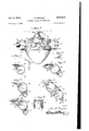
Fig. l is a front elevation of aircraft driving mechanism in accordance with my invention, illustrating the arrangement in which propeller blades are employed in connection with the cylinders of the reciprocating engines;
Fig. 2 is a plan view thereof;
Fig. 3 is a detail view of one of the propeller blades;
Fig. i is a similar View illustrating a' modification of the blade to also provide for conducting fluid pressure to the engine cylinders.
Fig. 5 is a vertical sectional view through the engine cylinders and circular casing enclosing the transmission gear;
Fig. 6 is an enlarged detail view of one of the reciprocating engines and transmission gear therefor;
Fig. '7 is a detail sectional view of the means for mounting certain elements of the transmission gear in the casing;
Fig. 3 is a similar view cation of the transmission gear;
Fig. 9 is a modification in the arrangement of the propeller blades with respect to the engine cylinders;
Fig. 10 is a modified form of propeller blade construction;
Fig. 11 to 15 inclusive show the employment of casings in connection with the engine cylinders to form propellers;
Fig. 16 is a detail view of one of the engine cylinders used in connection with the casing;
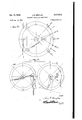
Fig. 17 is a vertical sectional view illustrating the arrangement of the reciprocating engines and transmission mechanism, including means for supplying fluid pressure to the engine cylinders from a source of supply (not shown) located in the fuselage of the airplane;
Fig. 18 is an elevation view of an element of the fluid pressure supply conduit; Fig. 18 is a detail sectional view thereof;
Fig. 19 is a vertical sectional view of fluid supply mechanism that may be employed in connection with the engine cylinders; Fig. 19 is a top plan view of the same with the top of the casing removed; and
Figs. 20 and 21 are diagrammatic views to illustrate the operations of the pistons in applystationary and the reciprocating engines with the transmission gear and crank-case revolve around the gearwheel-the small gearwheels of the transmission gear travelling around and in mesh with the toothed periphery of the large gearwheel to turn the crank-case for the operation of the propeller blades projecting radially therefrom.
Referring to the drawings, the center shaft lfi--projecting from the fuselage of the airplane-is held stationary, and a crank-case ll, revolving around the same, is provided with suitable bearing boxes l2, l3 while the large gearwheel I4 is keyed to the shaft and held stationary thereby so that the small gearwheels iii of the transmission gear, in .mesh with the large gearwheel, will be driven to proto illustrate a modifibolted to its side pieces;'
gress around the latter and turn the crank-case which carries the engine cylinders I6 and propeller blades I 1 projecting from the circumference thereof to operate in the propulsion of the aircraft.
The transmission gear associated with each reciprocating engine includes in addition to the gearwheel l a lever-wheel l8, and these wheels,
located side by side, are connected'together by:
a pin l9 near the outer edges thereof-the leverwheel being turned by piston-rod 20 connected thereto by pin 2| at the edge thereof opposite the connecting pin l9. Now to provide for a shifting movement of the lever-wheel so that greater leverage will be applied on the outstroke or P e of the piston said lever-wheel is mounted on a stub-shaft 22 through the medium of a diametrical'slot 2'3intowhich the stub-shaft projects from a large bearing 24 on which the gearwheel I5 is mounted for rotation; it being noted that the stub-shaft projects from the bearing at one side of the center or axisofthegearwheel and that the diametrical slot is also at one side of the center or axis of the lever-wheel, with the connections l9 and 2| on a line with the slot; whereby the change of location of the fulcrum in the slot during the turning of the lever-wheel by the piston-rod will apply-greater leverage on the lever-wheel during the power stroke of the piston than on the return or compression stro'ke- When this large gearwheel isemployed in connection with an S-cylinder enwheels is indirectly applied to the others by its operation in turning the crank-case aroundthe stationary gearwheel with which all the small gearwhe'els are in mesh and in the operation of the driving mechanism are turned under the influence of the large gearwheel in addition to the kinetic force applied to the lever-wheels by the pistons. Thus the operation of the several. reciprocating engines is implemented to' augment the power for rapidly revolving the propellers. The diagrammatic views (Figs. 20 and :21), hereinalfter explained, show examples of the timing of the transmission gears of the reciprocating engines.
The large bearing -for the gearwheel 15 isbolted :to one of the side pieces of the crankcase (Fig. 7), and :is provided with a boss 2-5 through which the stub-shaft 22 passes, with a spacing collar 26 interposed between the bossand lever -wheel to ease the shifting movement of the latter, and the pin connections between the wheels l5 and 1-8, and piston rod to the 'leVer-- wheel are headed to insure proper alignment. Although I have illustrated in Fig. 1'7 a transmission gear for each reciprocating engine as comprising a single lever wheel and gearwheelat one side of the reciprocating piston-rod-I may, and preferably will, employ these elements at opposite sides of the :piston rod, as shown in Fig. 8, so as to balance the operation 'of the transmission gears in relation to the strokes of therpiston.
Instead'of locating the propeller blades between the engine cylinders (Figs. 1 and 2) I may arrange them in circumferential series as shown in Fig. 9, wherein they are referred to by the numeral 21, and in this instance an adjoining pair of cylinders are connectedlby communicating pipes 28 cooperating with the feed pipe 29 from any source of fluid pressure suitably located in relation to the cylinders.
Any preferred form of bearing boxes may be employed for mounting the crank-case on the supporting shaft, and likewise in respect to means for conducting fluid pressure from a source (not shown), but preferably located in thefuselage of the aircraft. An example of these elements of construction is illustrated in Fig. 17 of. the drawings,.fromwhich it will be seen that the stationary shaft-supported in a bracket 31 integral therewith and bolted to the front wall of the fuselage is hollow or provided witha bore extending from the main supply pipe 32 to a point within the bearing box where it communicateswith radial passageways 33 in a disk 34: bolted between the parts 35 and 36 of the bearing box l2 and connected. to the crank-case by short bolts or studs 34*, with the feed pipes 29 connected tow the passageways at the periphery of the disk. As will be noted the disk revolves around an annular boss Iii formed integrally with the shaftwith the engaging surfaces at -an-angle-and that the boss is located between ball bearings confinedwithin the bearing box. The parts 35 and 3.6 of the bearing box-rotatable on the shaftare bolted to the opposite sides of the turnable disk 24, through holes 24* therein, and this bearing box includes gland nuts 31, 31 located at. the: outer ends thereof. To;
accommodate the bearing box the inner side of the crank-case. is cut away and reinforced around the opening to receive the aforementioned short bolts or studs which supplement the connection of the turnable disk and crank-case with the associated parts rotatable on the shaft; while the outer end of the shaft, which supports the bearing. box l3,v is threaded into the stationary part 40" of this bearing. and the connection secured by bolt l3", with the part 41' bolted to the outer wall of the crank-case-ball bearings being interposed to provide a thrust bearing at the outer end of the shaft in respect to the pulling force exerted on the shaft in the driving of the aircraft by the propellers carried by the crank-case. As the part 41 of bearing. l3 turns with the crank case to which it is bolted and the adjoining gearwheel I4 is stationary on the shaft to Which it is keyed these parts are spaced to leave a clearance, inasmuch as one is rotatable while the other remains stationary for the operation of the transmission gears functioning to revolve the crank-case.
The feed pipes 29 may pass through the crankcase (see dotted lines Fig. 9) instead of entirely outside of the-same. and as a further modification that portion of each feed pipe extending parallel with the engine cylinders may be dispensed with by employing hollow propeller blades 38 as shown in Fig. 4, with the supply pipes from the passageways in the disks connected to openings 39 in the periphery of the crank-case at the lower ends of the hollow propeller blades, and contemplates the .location of the disk 3 and companion annular boss ID- :at the inner side of the front wall of the crank-case when a single set :of transmission gears is employed; it being observed that in Fig. 8-showing two sets w transmission gears-1 have not included means,
such as hereinbefore described, for feeding fluid pressure to the engine cylinders as any other means for this purpose may be employed.
The supply of fluid pressure to the cylinders of the reciprocating engines is regulated by a cutoff valve t2 and exhaust valve 43 associated with the main supply pipe leading to the bore in the stationary shaft, and of course these valves are located in the fuselage of the aircraft; the operation of the cut-off valve with the exhaust valve closed effecting regulation in the speed of the aircraft while the closing of the cut-off valve and opening of the exhaust valve will stop operation of the engines.
The operation of that form of my invention hereinbefore described will be readily understood, inasmuch as it is obvious that the turning of the crank-case through the medium of the reciprocating engines, transmission gear and stationary gearwheel will cause the propeller blades carried by the crank-case to catch the air and drive the aircraft forward after the manner of propeller blades ordinarily employed; in this instance the cylinders of the reciprocating engines cooperating with the propeller blades by directing the air currents expelled from the blades around the rear of said cylinders to thereby implement the forward movement, augmented by the additional contact area of that portion of each blade which projects beyond the plane of the outer ends of the cylinders. Furthermore, the engine is an important desideratum in the construction of an aircraft, and therefore my improved construction of S-cylinder engine adds materially to the operation of other elements of construction of my improved propelling mechanism. Consequently I have illustrated in the diagrammatic views Figs. 20 and 21 the operation of the transmission gears, from which it will be observed that the shifting of the lever-wheel on its fulcrum-in response to the operation of the piston-effectively applies power in respect to both the power and compression strokes of the piston in the operation of the engine and driving of the gearwheels in mesh with the stationary gearwheel-the proportions being susceptible of variation by changes in the distance between centers and correspond ing changes in the diameters of the wheels. In any event the effective application of power is approximately 100 on the power stroke, that of each piston being transmitted to the others successively by the timing of the operation of the reciprocating engines of the S-cylinder motive power, regulated in such manner that the power stroke of one or more pistons will aid in the return stroke of the others. As illustrated in diagrammatic view Fig. 20, and assuming a predetermined disposition of centers and size of connected wheels, including the intermeshing gearwheels, the power stroke begins to be effective at a (approximately 62.6 pounds pressure) and gradually increases to point b, where the greatest amount of pressure is applied (estimated at 600 pounds) and then declines to the point c, approximately 62.6 pounds pressure-the shifting of centers from a: to 1,! having its effect on the return indicated by d, e, f. That is to say the ratio of power application on the power stroke of one of the pistons transmits comparatively greater force to the compression stroke of one or more of the other pistons through the medium of the transmission gear including the stationary gearwheel, for the reason that during the compression stroke-under the influence of the power stroke of a companion piston-rod-the connection between the piston-rod and lever-wheel is nearer the fulcrum of the latter, and accordingly maximum power is applied to the companion transmission gears, for the turning of the crankcase, through the entire range of travel of the gearwheels l5 in mesh with the stationary gearwheel-the greater leverage of the lever-wheel on the power stroke being applied directly to its companion rotatable gearwheel and also indirectly-by means of the gearing including the stationary gearwheel-to other rotatable gearwheels. Consequently the construction of reciprocating engine and associated transmission gear form an important part of the aircraft propelling mechanism constructed in accordance with my invention by cooperating to turn the crank case and propeller blades carried thereby.
As my invention contemplates various modifications in the construction and arrangement of essential parts I have illustrated in Figs. 11 to 15 inclusive the idea of having the reciprocating engine cylinders of such shape as to provide propeller blades to thereby dispense with the supplemental blades l'l-Fig. 11 being an exception in which the cylinder 44 is provided with extension 45 at the rear thereof and in the direction to cooperate with blade H from which it is spaced to provide an additional contact surface as well as a chamber 45 for supplying fluid pressure to the engine cylinder--a fuel supply pipe being connected to the chamber by way of opening 41 in the bottom thereof. This modification also suggests (by dotted 1ines) the provision of a front extension 45, and in the use of this construction of engine cylinder propeller blade H may be and preferably is omitted.
In Fig. 12 cylinder 48 is provided with an extension or casing 49, similar to 45, and an extension 59 in front of the engine cylinder, the last mentioned extension being reinforced by tube 5|; while in Fig. 13 the construction of the casing is somewhat similar--the front extension 52 being like extension 5t but at a different angle, with the extension 53 in the rear extended and reinforced by tube 54. The form of casing in Fig. 14 differs from that illustrated in Fig. 13 in that the front or forward extension 55 projects in like manner to the forward extension in Fig. 12, and the rear extensionreinforced by tube 51-presents a straight outer surface instead of having the opposite sides tapered to a point or vertical edge.
The propeller form of casing illustrated in Fig. 15 contemplates an arrangement of engine cylinders in pairs around the periphery of the crank case; it being understood, of course, that in this instance the reciprocating piston rods of the cylinders operate the respective transmission gear at opposite sides of the stationary gearwheel M in the crank-case. Consequently the cylinders 58, 58 are at an angle, being connected at opposite sides by straight walls 59, 59 for deflecting air currents in the operation of the casing'as propelling means, and include rearwardly projecting extension 68, tapered to an edge 6!, and a similar shaped forwardly projecting extension 62the inner wall of each extension being slightly curved inwardly for more eflicient operation as a propeller. This particular form of propeller casing in addition to increasing the effectiveness of the multiple cylinder engine by a more efficient disposition of the transmission gears presents greater air contact surfaces to permit the easings to be farther spaced apart around the periphery of the crank case without reducing the ntails.
number of enginecylinders. Itwill benotedthat fluid pressure'charnbers" 6} are provided aton posite sidesof each' cylinder, 58, and that the'cyl inders, as well as those. respect to, the other engine cylinders enclosed by the casings, are provided with. inlet op ing 64 (Fig. 16) at the up,-
ward, and that the arrangement combines in a single unit an engine cylinder, 'or cylinders, a propeller blade, and conduits for supplying fluid pressure to the engine cylinders, and is therefore an important modification, of the construction in which separate propeller blades are associ! ated with the engine cylinders as illustrated in Fig. 1 of the drawings.
As hereinbefore explained the purpose of the engine cylinder casings is to provide propellers operating in the manner of ordinary airplane propellers, and. for the reason that the propeller unit is susceptible of. variousjmodifications I have, illustrated in Fig. 19an arrangement in which the casing 65 includes an engine cylinder 66 and fuel supply chamberslfil. and 68 at opposite sides thereof, with one of 'the chambers, 68, serving as an expansion and contraction chamber, and for this purpose it is provided with a free mov: ing piston or diaphragm 69. intermediate its ends with the space in the lower part of the chamber acting as an air cushion supplied with air through opening Ill. Upward movement of the piston or diaphragmunder the influence of fluid pressure entering the upper part thereof through opening l-is limited by seat." in the form of a ring around the inner side of the chamber, and as shown chamber BBis spaced from the engine cyl inder by an interposed passageway or chamber, 13 between them. The engine cylinder contains piston 74, with its piston rod 15, and is provided with inlet ports 76 leading from chamber 61, andv ports 11' leading into chamber 13, as well as with h fuel S pply pipe. .8 and usual exhaust port (not shown). The purpose of this construction is to provide for rapid introduction of fuel or fluid pressure into the engine cylinder at the proper. moment during. the operation of the eng i'ne, augmented by ex ansion and contraction of the fuel in chamber 68, thus permitting quick pulsations through the influence of air'pressure on thepiston or diaphragm. Instead of employ,- ing air. pressure to influence the expansion and contraction of fluid pressure in chamber 68 a sprin may be employed, A valve (not shown) is connected to opening 10, and I prefer one similar to that employed'for the inflation of vehicle tires, though the valve will be dispensed with when the feed pipe is connected to an air-cornpressor.
' Other modifications or changes may be made in respect to details of construction, within the spirit and scope of the appended claims.
I claim:
1. Propelling mechanism for aircraft comprising a stationa y shaft connected to and project; ing from said aircraft and having a bore in the inner end portion thereof connected to a fuel supply on the aircraft, a crank-case mounted on the shaft to revolve around said stationary shaft, a stationary gearwheel keyed to the shaft, cylinders with reciprocating pistons spaced apart 8. ound the e ph o the, ota abl c an as conduits'for conducting fuel from the hollow shaft to the cylinders, andpropeller blades on, the crank case in association with the cylinders;
together with transmission gear between the pi s.
tons and stationarygearwheeLsaid transmission: gear including gearwheels in mesh with the sta; tionary gearwheel to travel around the toothedv periphery thereof to turn the crankcase for the operation of the propeller blades in association with the cylinders.
2. Propelling mechanism for aircraft in ac-. cordance with claim 1 and in which the transmission gear comprises in addition to the gear Wheels a lever-wheel connected to each of said gear wheels near the outer edge thereof, each of,
said. lever-wheels having a diametrical slot through which its fulcrum passes to permit shift ing movement of the lever-wheel in the applic'a tion of power thereto.the piston-rod of the p. 5?" ton being connected'to the lever-wheel opposite the connection of the lever-wheel to the small gearwheel on a line with the diametrical slot.
3. Propelling mechanism for aircraft comprising a hollow shaft fixed to and projecting front the aircraft, said hollow shaft communicating with a fuel supply on the aircraft, a stationary gearwheel keyed to the shaft, and a crank-case rotatably mounted on the shaft to revolve around.
the gearwheel; together with reciprocating pistons in cylinders carried by the crank-case with the cylinders arranged around the periphery of, the crank-case in spaced apart relation, propeller blades on the crank-case and associated with the cylinders, and conduits extending from the hole low shaft to the outer ends of the cylinders for supplying fluid pressure thereto.
4 Propelling mechanism for aircraft in accordance with claim 3. and in which the conduits for supplying fluid pressure to the engine cylinders includes a disk on the shaft having radial passageways communicating with the bore of the shaft, and supply pipes extending from the outer ends of the radial passageways to the outer ends of the cylinders.
JOHN E. BROYLES. REFERENCES cr'r n The following referenlces are of record in the file of this patent:
UNITED STATES PATENTS Number Name Date 58,891 Ruset Oct. 16, 1866 346,721 Cary Aug. 3, 1886 400,642 Kitson Oct. 6, 189; 1,057,225 Decker Mar. 25, 1913 1,340,450 Kleidman May 18, 1920 1,452,572 Prosser Apr. 24, 1923 1,529,111 Bowman Mar. 10, 1925 1,529,270 Pascolini Mar. 10, 1925 2,011,061 Loescher Aug. 13, 1935 2,028,526 Schulman Jan. 21, 1936. 2,308,380 Mercier Jan. 12, 1943 2,375,748 Broyles May 15, 19 5 FOREIGN PATENTS Number Country Date 14,595 Great Britain July 15, 1905 389,288 France Sept. 4, 1908' 397,499 France May 8, 190.9 108,033 France Mar. 16, 1910
Priority Applications (1)
| Application Number | Priority Date | Filing Date | Title |
|---|---|---|---|
| US549583A US2475813A (en) | 1944-08-15 | 1944-08-15 | Aircraft propelling mechanism |
Applications Claiming Priority (1)
| Application Number | Priority Date | Filing Date | Title |
|---|---|---|---|
| US549583A US2475813A (en) | 1944-08-15 | 1944-08-15 | Aircraft propelling mechanism |
Publications (1)
| Publication Number | Publication Date |
|---|---|
| US2475813A true US2475813A (en) | 1949-07-12 |
Family
ID=24193585
Family Applications (1)
| Application Number | Title | Priority Date | Filing Date |
|---|---|---|---|
| US549583A Expired - Lifetime US2475813A (en) | 1944-08-15 | 1944-08-15 | Aircraft propelling mechanism |
Country Status (1)
| Country | Link |
|---|---|
| US (1) | US2475813A (en) |
Citations (16)
| Publication number | Priority date | Publication date | Assignee | Title |
|---|---|---|---|---|
| FR408033A (en) * | ||||
| US58891A (en) * | 1866-10-16 | Improvement in revolving-cylinder engines | ||
| US346721A (en) * | 1886-08-03 | Chaeles h | ||
| US460642A (en) * | 1891-10-06 | Variable crank-motion | ||
| GB190514595A (en) * | 1905-07-15 | 1906-05-24 | Henry Shepley Booth | Improvements in Fluid Pressure Motors. |
| FR389288A (en) * | 1908-04-16 | 1908-09-04 | Joseph Michel Ambroise Farcot | Propeller motor for aircraft, navigation or the like |
| FR397499A (en) * | 1908-12-15 | 1909-05-08 | Georges Henri Marius Canton | Automatically balanced reaction thruster |
| US1057225A (en) * | 1911-04-03 | 1913-03-25 | Harry R Decker | Aeroplane. |
| US1340450A (en) * | 1917-12-11 | 1920-05-18 | Kleidman Joseph | Aeroplane |
| US1452572A (en) * | 1922-01-21 | 1923-04-24 | Harold T Prosser | Engine |
| US1529270A (en) * | 1922-03-20 | 1925-03-10 | Pascolini Hans | Revolving fluid-pressure motor |
| US1529111A (en) * | 1922-11-07 | 1925-03-10 | Oliver S Bowman | Rotary steam engine |
| US2011061A (en) * | 1931-10-15 | 1935-08-13 | Frederick E Loescher | Aeroplane motor-propeller structure |
| US2028526A (en) * | 1931-06-30 | 1936-01-21 | Schulman Henry | Rotary internal combustion engine |
| US2308380A (en) * | 1941-01-06 | 1943-01-12 | Mercier Jean | Hydraulic motor |
| US2375748A (en) * | 1943-06-05 | 1945-05-15 | John E Broyles | Transmission mechanism for reciprocating engines |
-
1944
- 1944-08-15 US US549583A patent/US2475813A/en not_active Expired - Lifetime
Patent Citations (16)
| Publication number | Priority date | Publication date | Assignee | Title |
|---|---|---|---|---|
| FR408033A (en) * | ||||
| US58891A (en) * | 1866-10-16 | Improvement in revolving-cylinder engines | ||
| US346721A (en) * | 1886-08-03 | Chaeles h | ||
| US460642A (en) * | 1891-10-06 | Variable crank-motion | ||
| GB190514595A (en) * | 1905-07-15 | 1906-05-24 | Henry Shepley Booth | Improvements in Fluid Pressure Motors. |
| FR389288A (en) * | 1908-04-16 | 1908-09-04 | Joseph Michel Ambroise Farcot | Propeller motor for aircraft, navigation or the like |
| FR397499A (en) * | 1908-12-15 | 1909-05-08 | Georges Henri Marius Canton | Automatically balanced reaction thruster |
| US1057225A (en) * | 1911-04-03 | 1913-03-25 | Harry R Decker | Aeroplane. |
| US1340450A (en) * | 1917-12-11 | 1920-05-18 | Kleidman Joseph | Aeroplane |
| US1452572A (en) * | 1922-01-21 | 1923-04-24 | Harold T Prosser | Engine |
| US1529270A (en) * | 1922-03-20 | 1925-03-10 | Pascolini Hans | Revolving fluid-pressure motor |
| US1529111A (en) * | 1922-11-07 | 1925-03-10 | Oliver S Bowman | Rotary steam engine |
| US2028526A (en) * | 1931-06-30 | 1936-01-21 | Schulman Henry | Rotary internal combustion engine |
| US2011061A (en) * | 1931-10-15 | 1935-08-13 | Frederick E Loescher | Aeroplane motor-propeller structure |
| US2308380A (en) * | 1941-01-06 | 1943-01-12 | Mercier Jean | Hydraulic motor |
| US2375748A (en) * | 1943-06-05 | 1945-05-15 | John E Broyles | Transmission mechanism for reciprocating engines |
Similar Documents
| Publication | Publication Date | Title |
|---|---|---|
| US2989022A (en) | Internal combustion engine | |
| US2513446A (en) | Pump or motor | |
| US2475813A (en) | Aircraft propelling mechanism | |
| US1838974A (en) | Internal combustion engine | |
| US2923124A (en) | Pulses tx prxvide a prxpelling | |
| US1358954A (en) | Multicylinder engine | |
| US2505951A (en) | Rotary engine | |
| US3171494A (en) | Servo mechanism for controllable pitch propellers | |
| GB330671A (en) | Improved brake for use on road vehicles | |
| US2650676A (en) | Lubrication of wobble plate internal-combustion engines | |
| US2316278A (en) | Drive | |
| US2185902A (en) | Articulating rod bearing for radial motors | |
| US2018794A (en) | Mounting for internal combustion engines | |
| US3306171A (en) | Fluid operated device | |
| US1670294A (en) | Internal-combustion engine | |
| US1831983A (en) | Motor vehicle | |
| US1329033A (en) | Aeroplane-motor | |
| US2483349A (en) | Hydraulic power installation | |
| DE358643C (en) | Pressurized water generation system consisting of a pump and an explosion engine | |
| US1762590A (en) | Hydraulic transmission system | |
| US1999374A (en) | Internal combustion engine | |
| US1319100A (en) | Internal-combustion engine | |
| US4827717A (en) | Daerohydrophase engine | |
| US2188831A (en) | Dual crank and connecting rod assembly | |
| US1528836A (en) | Single-acting reversible steam engine |