US2464181A - Rocket device - Google Patents
Rocket device Download PDFInfo
- Publication number
- US2464181A US2464181A US481644A US48164443A US2464181A US 2464181 A US2464181 A US 2464181A US 481644 A US481644 A US 481644A US 48164443 A US48164443 A US 48164443A US 2464181 A US2464181 A US 2464181A
- Authority
- US
- United States
- Prior art keywords
- grain
- combustion
- motor
- motor body
- rocket
- Prior art date
- Legal status (The legal status is an assumption and is not a legal conclusion. Google has not performed a legal analysis and makes no representation as to the accuracy of the status listed.)
- Expired - Lifetime
Links
- 238000002485 combustion reaction Methods 0.000 description 20
- 239000003380 propellant Substances 0.000 description 15
- 239000000843 powder Substances 0.000 description 9
- 239000000463 material Substances 0.000 description 4
- 239000004451 Ballistite Substances 0.000 description 2
- 229920002160 Celluloid Polymers 0.000 description 2
- 235000015842 Hesperis Nutrition 0.000 description 2
- 235000012633 Iberis amara Nutrition 0.000 description 2
- 238000010276 construction Methods 0.000 description 2
- 230000007423 decrease Effects 0.000 description 2
- 239000000835 fiber Substances 0.000 description 2
- 239000007787 solid Substances 0.000 description 2
- 241000663501 Anisocampium skinneri Species 0.000 description 1
- 229910000831 Steel Inorganic materials 0.000 description 1
- 239000011248 coating agent Substances 0.000 description 1
- 238000000576 coating method Methods 0.000 description 1
- 150000001875 compounds Chemical class 0.000 description 1
- 239000004020 conductor Substances 0.000 description 1
- 239000002274 desiccant Substances 0.000 description 1
- 239000002360 explosive Substances 0.000 description 1
- 238000009413 insulation Methods 0.000 description 1
- 239000004922 lacquer Substances 0.000 description 1
- 230000000750 progressive effect Effects 0.000 description 1
- 238000007789 sealing Methods 0.000 description 1
- 239000010959 steel Substances 0.000 description 1
- XLYOFNOQVPJJNP-UHFFFAOYSA-N water Substances O XLYOFNOQVPJJNP-UHFFFAOYSA-N 0.000 description 1
Images

Classifications
-
- F—MECHANICAL ENGINEERING; LIGHTING; HEATING; WEAPONS; BLASTING
- F42—AMMUNITION; BLASTING
- F42B—EXPLOSIVE CHARGES, e.g. FOR BLASTING, FIREWORKS, AMMUNITION
- F42B15/00—Self-propelled projectiles or missiles, e.g. rockets; Guided missiles
Definitions
- This invention relates to jet propulsion rockets and more particularly to a novel rocket motor having a solid grain of combustible propellant supported in a motor body to drive the motor by simultaneous comb ction of internal and eX- ternal surfaces of the grain.
- the new motor is simple and compact in construction, provides an accurate flight, and affords improved combustion over prior motors of this type. Accordingly, the invention may be used to particular advantage for projecting bombs, flares, and the like, in weapons requiring a high degree of accuracy and facilityv in handling, although it is to be understood that the invention may be used for other purposes as well.
- Rocket motors as commonly made have a propellant charge in either one of two general forms.
- a solid charge of propellant is employed which completely fills the combustion chamber, as disclosed in a patent to L. A. Skin ner, No, 2,206,057, while in another form the charge is compressed into a grain which fits closely against the wall of the combustion chamber and has a central longitudinal passage or core, as disclosed in a patent to Stolfa et al.. No. 1,901,852.
- a rocket made in accordance with my invention comprises a cylindrical motor body containing a single grain of propellant, such as ballistite, and having a nozzle in its rear end portion through which the products of combustion of the propellant are discharged.
- the propellant grain is generally cylindrical in form and has an initial internal combustion surface of substantial area defining an axial passage. The initial combustion, however,
- the grain is not confined to the internal surface in the passage, and to this end I mount the propellant grain with its external cylindrical surface in spaced relation to the wall of the motor body, whereby the external surface is free to burn simultaneously with the internal surface.
- the grain is provided with a series of radial openings arranged in a helix along its length, as I have found that by the use of such openings the burning characteristics of the grain may be considerably improved and the internal and external pressures on the grain tend to equalize so as to reduce the mechanical strain thereon,
- Another object of the invention is to provide a rocket motor having novel means for supporting the propellant grain securely in position to obtain combustion simultaneously on its internal and external surfaces.
- the grain is provided with longitudinal ribs on its outer cylindrical surface, and the ribs engage the inner wall of the motor body so as to support the grain along its length with a substantial clearance between the motor body and the cylindrical surface of the grain.
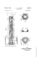
- FIG. 1 is a longitudinal sectional view of a rocket-propelled device embodying one form of the new motor, with the parts in the motor body removed;
- Fig. 2 is an enlarged longitudinal sectional View of the motor shown in Fig. 1;
- Fig. 3 is a detail view of the powder grain for the motor
- Fig.4 is a sectional view on the line i4 in Fig. 3;
- Fig. 5 is an end view of the saddle for supporting one end of the grain
- Fig. 7 is an end view of the grid for supporting the opposite end of the powder grain.
- the motor I is shown connected to a pay load II in the form of an antisubmarine bomb comprising a casing l2 for receiving a high explosive charge (not shown).
- the nose portion of the bomb casing is substantially fiat to cause the assembly to assume a substantially vertical position when it strikes the Water, and in the central portion of the nose is an annular rim l3 in which a liner I4 is threaded.
- the liner projects into the casing [2 and is adapted to receive a suitable fuze (not shown), such as a hydrostatically-armed, impact-fired fuze, for detonatin the main charge in the casing.
- a plug Ma is threaded in the open end of the liner and may be removed when the fuze is to be inserted.
- the motor Iii comprises a cylindrical body it, which may be made of seamless steel tubing, connected at its front end to the bomb casing l2 by means of a generally cup-shaped adapter H.
- the adapter is welded in a recess in the rear end of the bomb casing, and the motor body it is threaded in the open end of the adapter.
- a propellant charge in the form of a cylindrical powder grain l8, such as ballistite, the grain having an axial passage it extending through it and also having spaced longitudinal ribs 26 on its outer cylindrical surface.
- the powder grain fits closely in the motor body on the ribs 29 which serve to space the outer cylindrical surface of the grain from the inner Wall of the motor body to provide external combustion surfaces between the ribs.
- the grain has a series of radial openings 2i arranged in a helix along its length, each opening being spaced from the adjacent opening a distance equal substantially to twice the diameter of the axial passage !9, and each opening having a diameter equal to substantially one-half the web thickness of the grain, that is, to substantially one-half the difference between the internal and external diameters of the grain.
- the longitudinal ribs 2i? may be in the form of strips of combustible material, such as Celluloid, cemented to the grain or they may be integral with the grain. Contact between the ribs and the motor body may be prevented by a lacquer coating on the inner wall of the body.
- the grain I8 is supported in the motor body by a saddle 23 cemented to the end of the grain and having a central opening aligned with the passage l9.
- the saddle is preferably made of Celluloid or other combustible material and is provided on its edge portion with spaced tabs 2 extending forwardly from the grain.
- An electrically operable igniter 25 near the front end of the motor body is spaced from the face of saddle 23, the igniter fitting closely against the tabs 24 and being held in spaced relation to the face of the saddle by shoulders 26 on the tabs.
- the igniter is supported on the tabs 24, and the latter are clamped between the igniter and the inner wall of the motor body.
- a fiber closure disc 2 ?
- the igniter is adapted to be energized through leads 2?? and 36 extending through the saddle into the grain passage l9, where the leads are connected to wires 29a and 3M by joints (ill.
- the rear end of the powder grain I is supported by a grid comprising a ring 32 having radial legs 33 which engage the inner wall of the motor body so as to support the ring with its opening in concentric relation to the motor body.
- the grid ring is connected to the adjacent end 7 around the body and disposed end to end in closely spaced relation.
- the rings are concentric with the motor body and are supported thereon by radial fins id which may be connected at their inner ends to the side wall of the motor body, and at their outer ends to the inner surfaces of the rings 33 and 39.
- the forward ring 39 is insulated from the fins :10 by suitable insulation 3% and has a terminal il which is likewise insulated from the fins.
- the ring 39 is electrically connected through the terminal ii and an insulated conductor 42 to a second insulated terminal 33 on one of the fins 40.
- the fin diametrically opposite the terminal 43 has a terminal 44 connected to the wire 29a which extends through the grid 32 and the nozzle.
- the wire 30a extends through the grid and the nozzle and is connected to the insulated terminal :13.
- the interior of the motor body it is sealed by a fiber disc 45 in the nozzle, and a container of desiccant material 46 is mounted in the nozzle to absorb any moisture in the motor body.
- the rocket assembly is adapted to be mounted in a trough-shaped projector or guide having a pair of knife-blade contacts engaging the rings 38 and 39, respectively, whereby the igniter 25 may be energized through the projector contacts, the rings 38 and 39 and the Wires 29 and 30.
- the resulting blast is communicated through the space between the igniter and the adjacent end of the powder grain into the axial passage l9 and the external combustion spaces between the ribs 20. Accordingly, the powder grain burns simultaneously on its internal and external surfaces, and as the internal surface defining the passage I9 increases due to combustion, the external surface decreases so that the total combustion surface remains substantially constant, whereby the usual abrupt changes in pressure are avoided.
- the radial openings 2! in the grain tend to improve its combustion characteristics, providing more uniform burning and more constant pressure. Also, the openings 2! tend to equalize the pressures in passage l9 and the space around the outside of the grain, so as to reduce the mechanical strain on the grain.
- a rocket motor comprising a hollow body of generally cylindrical form, a generally cylindrical grain of propellant charge in the body hav- 5 ing an axial passage and radial openings spaced along its length, longitudinal ribs on the grain for supporting it in the body to provide between the grain and the cylindrical wall of said body a substantial clearance communicating with the passage through the radial openings, a grid in the body at the rear end of the grain and having an anal opening aligned with said passage, a combustible washer connecting the grain to the grid, the cylindrical outer wall of the grain and the walls of said passage and radial openings forming initial combustion surfaces, an igniter in the body at the front end of the grain for igniting the grain whereby said surfaces burn simultaneously, a combustible saddle connected to the front end of the grain and having a part disposed between the igniter and a Wall of said body, and a nozzle in the rear end of the body aligned with said grid opening and through which the products of combustion of the propellant are discharged.
Landscapes
- Engineering & Computer Science (AREA)
- Chemical & Material Sciences (AREA)
- Aviation & Aerospace Engineering (AREA)
- Combustion & Propulsion (AREA)
- General Engineering & Computer Science (AREA)
- Aiming, Guidance, Guns With A Light Source, Armor, Camouflage, And Targets (AREA)
Description
March 8, 1949. c. c. LAURITSEN ROCKET DEVICE 2 sheets-s et 1 Filed April 2' 43 March 8, 1949. c. c. LAURITSEN 2,464,181
ROCKET DEVICE Filed April 2, 1943 ZSheets-Sheet 2 NV vw 3 QA on R 8 m R a v 2 v lllllh I lNVENTOR BY CHARLES 62 LAUR/TSE/V 7/ A TORNEY Patented Mar. 8, 1949 UNITED STATE GFFICE RQCKET DEVICE Charles C. Lauritsen, Pasadena, Calif., assignor to the United States of America as represented by the Secretary of the Navy Application April 2, 1943, Serial No. 481,644
1 Claim. 1
This invention relates to jet propulsion rockets and more particularly to a novel rocket motor having a solid grain of combustible propellant supported in a motor body to drive the motor by simultaneous comb ction of internal and eX- ternal surfaces of the grain. The new motor is simple and compact in construction, provides an accurate flight, and affords improved combustion over prior motors of this type. Accordingly, the invention may be used to particular advantage for projecting bombs, flares, and the like, in weapons requiring a high degree of accuracy and facilityv in handling, although it is to be understood that the invention may be used for other purposes as well.
One of the diificulties encountered heretofore in jet propulsion rockets is to obtain proper combustion of the propellant charge at the desired rate. Rocket motors as commonly made have a propellant charge in either one of two general forms. In one form, a solid charge of propellant is employed which completely fills the combustion chamber, as disclosed in a patent to L. A. Skin ner, No, 2,206,057, while in another form the charge is compressed into a grain which fits closely against the wall of the combustion chamber and has a central longitudinal passage or core, as disclosed in a patent to Stolfa et al.. No. 1,901,852. The burning characteristics of these propellants are not entirely satisfactory for vari-- ous reasons, among which are their non-uniformity of combustion resulting in widely differing flight trajectories for identical IOCK.LS, development of excessive abrupt changes in pressure, and the fact that a substantial part of the propulsion power is generated after the rocket leaves the guide or projector, due to progressive burnin of the charge, whereby the flight is inaccurate.
One object of the present invention, therefore, resides in the provision of a novel rocket motor whichovercomes the above-mentioned difficulties in prior motors of this type and which the combustion of the propellant charge is controlled so that accurate flight of the rocket through a uniform trajectory may be had. A rocket made in accordance with my invention comprises a cylindrical motor body containing a single grain of propellant, such as ballistite, and having a nozzle in its rear end portion through which the products of combustion of the propellant are discharged. The propellant grain is generally cylindrical in form and has an initial internal combustion surface of substantial area defining an axial passage. The initial combustion, however,
Ill)
is not confined to the internal surface in the passage, and to this end I mount the propellant grain with its external cylindrical surface in spaced relation to the wall of the motor body, whereby the external surface is free to burn simultaneously with the internal surface. Preferably, the grain is provided with a series of radial openings arranged in a helix along its length, as I have found that by the use of such openings the burning characteristics of the grain may be considerably improved and the internal and external pressures on the grain tend to equalize so as to reduce the mechanical strain thereon,
Another object of the invention is to provide a rocket motor having novel means for supporting the propellant grain securely in position to obtain combustion simultaneously on its internal and external surfaces. In accordance with my invention, the grain is provided with longitudinal ribs on its outer cylindrical surface, and the ribs engage the inner wall of the motor body so as to support the grain along its length with a substantial clearance between the motor body and the cylindrical surface of the grain. With this construction, the outer surface of the grain-burns simultaneously with the inner surface defining the axial passage, and as the inner surface increases in area due to burning, the outer surface decreases in area so that the total burning surface remains substantially constant. Accordingly, the usual sudden changes in pressure during combustion are reduced, the propellant power is generated more smoothly, and the combustion is accelerated, without excessive pressures, so that substantially all of the power is expended while the rocket is still in the projector, resultingin greater flight accuracy.
These and other objects of the invention may be better understood by reference to the accompanying drawings, in which Fig. 1 is a longitudinal sectional view of a rocket-propelled device embodying one form of the new motor, with the parts in the motor body removed;
Fig. 2 is an enlarged longitudinal sectional View of the motor shown in Fig. 1;
Fig. 3 is a detail view of the powder grain for the motor;
Fig.4 is a sectional view on the line i4 in Fig. 3;
Fig. 5 is an end view of the saddle for supporting one end of the grain;
6 is a sectional View on the line 65 in Fig. 5, and
Fig. 7 is an end view of the grid for supporting the opposite end of the powder grain.
Referring to the drawings, the motor I is shown connected to a pay load II in the form of an antisubmarine bomb comprising a casing l2 for receiving a high explosive charge (not shown). The nose portion of the bomb casing is substantially fiat to cause the assembly to assume a substantially vertical position when it strikes the Water, and in the central portion of the nose is an annular rim l3 in which a liner I4 is threaded. The liner projects into the casing [2 and is adapted to receive a suitable fuze (not shown), such as a hydrostatically-armed, impact-fired fuze, for detonatin the main charge in the casing. A plug Ma is threaded in the open end of the liner and may be removed when the fuze is to be inserted.
The motor Iii comprises a cylindrical body it, which may be made of seamless steel tubing, connected at its front end to the bomb casing l2 by means of a generally cup-shaped adapter H. The adapter is welded in a recess in the rear end of the bomb casing, and the motor body it is threaded in the open end of the adapter. Within the motor body is a propellant charge in the form of a cylindrical powder grain l8, such as ballistite, the grain having an axial passage it extending through it and also having spaced longitudinal ribs 26 on its outer cylindrical surface.
The powder grain fits closely in the motor body on the ribs 29 which serve to space the outer cylindrical surface of the grain from the inner Wall of the motor body to provide external combustion surfaces between the ribs. Preferably, the grain has a series of radial openings 2i arranged in a helix along its length, each opening being spaced from the adjacent opening a distance equal substantially to twice the diameter of the axial passage !9, and each opening having a diameter equal to substantially one-half the web thickness of the grain, that is, to substantially one-half the difference between the internal and external diameters of the grain. The longitudinal ribs 2i? may be in the form of strips of combustible material, such as Celluloid, cemented to the grain or they may be integral with the grain. Contact between the ribs and the motor body may be prevented by a lacquer coating on the inner wall of the body.
At its front end, the grain I8 is supported in the motor body by a saddle 23 cemented to the end of the grain and having a central opening aligned with the passage l9. The saddle is preferably made of Celluloid or other combustible material and is provided on its edge portion with spaced tabs 2 extending forwardly from the grain. An electrically operable igniter 25 near the front end of the motor body is spaced from the face of saddle 23, the igniter fitting closely against the tabs 24 and being held in spaced relation to the face of the saddle by shoulders 26 on the tabs. Thus, the igniter is supported on the tabs 24, and the latter are clamped between the igniter and the inner wall of the motor body. A fiber closure disc 2? is mounted in the motor body directly in front of the igniter and adjacent the closed end of the adapter H, the disc being preferably sealed along its edges by a suitable sealing compound. The igniter is adapted to be energized through leads 2?? and 36 extending through the saddle into the grain passage l9, where the leads are connected to wires 29a and 3M by joints (ill.
The rear end of the powder grain I it is supported by a grid comprising a ring 32 having radial legs 33 which engage the inner wall of the motor body so as to support the ring with its opening in concentric relation to the motor body.
The grid ring is connected to the adjacent end 7 around the body and disposed end to end in closely spaced relation. The rings are concentric with the motor body and are supported thereon by radial fins id which may be connected at their inner ends to the side wall of the motor body, and at their outer ends to the inner surfaces of the rings 33 and 39.
The forward ring 39 is insulated from the fins :10 by suitable insulation 3% and has a terminal il which is likewise insulated from the fins. The
As disclosed in my above-identified copending application, the rocket assembly is adapted to be mounted in a trough-shaped projector or guide having a pair of knife-blade contacts engaging the rings 38 and 39, respectively, whereby the igniter 25 may be energized through the projector contacts, the rings 38 and 39 and the Wires 29 and 30.
When the igniter 25 is fired, the resulting blast is communicated through the space between the igniter and the adjacent end of the powder grain into the axial passage l9 and the external combustion spaces between the ribs 20. Accordingly, the powder grain burns simultaneously on its internal and external surfaces, and as the internal surface defining the passage I9 increases due to combustion, the external surface decreases so that the total combustion surface remains substantially constant, whereby the usual abrupt changes in pressure are avoided. I have found that the radial openings 2! in the grain tend to improve its combustion characteristics, providing more uniform burning and more constant pressure. Also, the openings 2! tend to equalize the pressures in passage l9 and the space around the outside of the grain, so as to reduce the mechanical strain on the grain. It will be apparent that the products of combustion of the powder grain are discharged under pressure through the grid 32 and the nozzle. By making the saddle 23 and the washer 34 of a combustible material, these members burn and provide additional pressure in the motor body upon ignition of the powder grain.
I claim:
A rocket motor comprising a hollow body of generally cylindrical form, a generally cylindrical grain of propellant charge in the body hav- 5 ing an axial passage and radial openings spaced along its length, longitudinal ribs on the grain for supporting it in the body to provide between the grain and the cylindrical wall of said body a substantial clearance communicating with the passage through the radial openings, a grid in the body at the rear end of the grain and having an anal opening aligned with said passage, a combustible washer connecting the grain to the grid, the cylindrical outer wall of the grain and the walls of said passage and radial openings forming initial combustion surfaces, an igniter in the body at the front end of the grain for igniting the grain whereby said surfaces burn simultaneously, a combustible saddle connected to the front end of the grain and having a part disposed between the igniter and a Wall of said body, and a nozzle in the rear end of the body aligned with said grid opening and through which the products of combustion of the propellant are discharged.
CHARLES C. LAURITSEN.
REFERENCES CITED The following references are of record in the file of this patent:
UNITED STATES PATENTS Number Name Date 677,528 Maxim July 2, 1901 726,901 Gathmann May 5, 1903 989,375 Luciani Apr. 11, 1911 1,360,602 Van Deuren Nov. 30, 1920 FOREIGN PATENTS Number Country Date 502,560 France Feb. 24, 1920 831,496 France Jan. 7, 1938
Priority Applications (1)
| Application Number | Priority Date | Filing Date | Title |
|---|---|---|---|
| US481644A US2464181A (en) | 1943-04-02 | 1943-04-02 | Rocket device |
Applications Claiming Priority (1)
| Application Number | Priority Date | Filing Date | Title |
|---|---|---|---|
| US481644A US2464181A (en) | 1943-04-02 | 1943-04-02 | Rocket device |
Publications (1)
| Publication Number | Publication Date |
|---|---|
| US2464181A true US2464181A (en) | 1949-03-08 |
Family
ID=23912801
Family Applications (1)
| Application Number | Title | Priority Date | Filing Date |
|---|---|---|---|
| US481644A Expired - Lifetime US2464181A (en) | 1943-04-02 | 1943-04-02 | Rocket device |
Country Status (1)
| Country | Link |
|---|---|
| US (1) | US2464181A (en) |
Cited By (11)
| Publication number | Priority date | Publication date | Assignee | Title |
|---|---|---|---|---|
| US2688920A (en) * | 1952-07-24 | 1954-09-14 | Ici Ltd | Gas generating cartridge |
| US2766507A (en) * | 1952-08-15 | 1956-10-16 | S W Farber Inc | Process of forming a casing for a rocket charge |
| US2813487A (en) * | 1945-09-26 | 1957-11-19 | Glen W Miller | Deflagration inhibited powder grains and method of making same |
| US2865456A (en) * | 1956-08-22 | 1958-12-23 | Specialties Dev Corp | Pressurizing cartridge and pyrotechnic charge therefor |
| US2976678A (en) * | 1955-12-19 | 1961-03-28 | Standard Oil Co | Restricted solid propellant |
| US2986092A (en) * | 1955-10-03 | 1961-05-30 | Phillips Petroleum Co | Rocket grain and process for making same |
| US2998704A (en) * | 1956-08-13 | 1961-09-05 | Phillips Petroleum Co | Ignition of solid rocket propellants |
| US3017744A (en) * | 1957-07-11 | 1962-01-23 | James A Jett | Propellant grain and rocket motor |
| US3048112A (en) * | 1959-02-06 | 1962-08-07 | Phillips Petroleum Co | Gas generator |
| US3069843A (en) * | 1958-05-29 | 1962-12-25 | Phillips Petroleum Co | Ignition of solid propellants |
| US3099963A (en) * | 1950-12-11 | 1963-08-06 | Dobrin Saxe | Outward burning neutral granulation for cast propellants |
Citations (6)
| Publication number | Priority date | Publication date | Assignee | Title |
|---|---|---|---|---|
| US677528A (en) * | 1899-08-24 | 1901-07-02 | Hudson Maxim | Cartridge. |
| US726901A (en) * | 1899-05-27 | 1903-05-05 | George Whitman Mcmullen | Explosive charge. |
| US989375A (en) * | 1907-12-19 | 1911-04-11 | Jacques Luciani | Explosive. |
| FR502560A (en) * | 1916-08-21 | 1920-05-19 | Procedes Westinghouse Leblanc | Aerial torpedo |
| US1360602A (en) * | 1919-02-04 | 1920-11-30 | Procedes Westinghouse Leblanc | Projectile |
| FR831496A (en) * | 1937-01-04 | 1938-09-05 | Sageb | Projectile fitted with a propellant rocket |
-
1943
- 1943-04-02 US US481644A patent/US2464181A/en not_active Expired - Lifetime
Patent Citations (6)
| Publication number | Priority date | Publication date | Assignee | Title |
|---|---|---|---|---|
| US726901A (en) * | 1899-05-27 | 1903-05-05 | George Whitman Mcmullen | Explosive charge. |
| US677528A (en) * | 1899-08-24 | 1901-07-02 | Hudson Maxim | Cartridge. |
| US989375A (en) * | 1907-12-19 | 1911-04-11 | Jacques Luciani | Explosive. |
| FR502560A (en) * | 1916-08-21 | 1920-05-19 | Procedes Westinghouse Leblanc | Aerial torpedo |
| US1360602A (en) * | 1919-02-04 | 1920-11-30 | Procedes Westinghouse Leblanc | Projectile |
| FR831496A (en) * | 1937-01-04 | 1938-09-05 | Sageb | Projectile fitted with a propellant rocket |
Cited By (11)
| Publication number | Priority date | Publication date | Assignee | Title |
|---|---|---|---|---|
| US2813487A (en) * | 1945-09-26 | 1957-11-19 | Glen W Miller | Deflagration inhibited powder grains and method of making same |
| US3099963A (en) * | 1950-12-11 | 1963-08-06 | Dobrin Saxe | Outward burning neutral granulation for cast propellants |
| US2688920A (en) * | 1952-07-24 | 1954-09-14 | Ici Ltd | Gas generating cartridge |
| US2766507A (en) * | 1952-08-15 | 1956-10-16 | S W Farber Inc | Process of forming a casing for a rocket charge |
| US2986092A (en) * | 1955-10-03 | 1961-05-30 | Phillips Petroleum Co | Rocket grain and process for making same |
| US2976678A (en) * | 1955-12-19 | 1961-03-28 | Standard Oil Co | Restricted solid propellant |
| US2998704A (en) * | 1956-08-13 | 1961-09-05 | Phillips Petroleum Co | Ignition of solid rocket propellants |
| US2865456A (en) * | 1956-08-22 | 1958-12-23 | Specialties Dev Corp | Pressurizing cartridge and pyrotechnic charge therefor |
| US3017744A (en) * | 1957-07-11 | 1962-01-23 | James A Jett | Propellant grain and rocket motor |
| US3069843A (en) * | 1958-05-29 | 1962-12-25 | Phillips Petroleum Co | Ignition of solid propellants |
| US3048112A (en) * | 1959-02-06 | 1962-08-07 | Phillips Petroleum Co | Gas generator |
Similar Documents
| Publication | Publication Date | Title |
|---|---|---|
| US4702167A (en) | Propellant-charge module | |
| US2464181A (en) | Rocket device | |
| US3482516A (en) | Caseless cartridges having the projectile housed in the propellant charge | |
| US3808973A (en) | Self-propelling projectile for firearms | |
| GB1510986A (en) | Projectile with an ejectable payload | |
| US4671179A (en) | Cartridged ammunition for gun barrel weapons | |
| US3555825A (en) | Dual solid fuel propellant rocket engine | |
| US3044255A (en) | Powder propulsive for rockets or other self-propelled projectiles | |
| US3392673A (en) | Consumable pyrogen igniter | |
| US3142152A (en) | Hybrid rocket motor | |
| US2515048A (en) | Multiple rocket motor | |
| US2814179A (en) | Return burning motor | |
| US3340809A (en) | Cartridge | |
| US4282814A (en) | Dual-end warhead initiation system | |
| RU2024776C1 (en) | Rocket engine for projectile | |
| US2683415A (en) | Rocket motor | |
| US3732819A (en) | Simultaneous axially & radially ignited caseless telescopic tube ammunition round | |
| US3014425A (en) | Peripheral ignition system | |
| GB1458809A (en) | Missile warheads | |
| US3413888A (en) | Electrically-actuated cartridge | |
| US3645206A (en) | Ammunition cartridge | |
| US3204559A (en) | Rocket propellant charge igniter | |
| US3951072A (en) | Propellant grain | |
| US3434419A (en) | Rocket assisted projectile with movable piston base plate | |
| GB1586109A (en) | Solid propellant rocket propulsion means for accelerating a projectile along a launching tube |