US2444619A - Electrical timing device - Google Patents
Electrical timing device Download PDFInfo
- Publication number
- US2444619A US2444619A US613656A US61365645A US2444619A US 2444619 A US2444619 A US 2444619A US 613656 A US613656 A US 613656A US 61365645 A US61365645 A US 61365645A US 2444619 A US2444619 A US 2444619A
- Authority
- US
- United States
- Prior art keywords
- magnet
- contacts
- relay
- circuit
- movable element
- Prior art date
- Legal status (The legal status is an assumption and is not a legal conclusion. Google has not performed a legal analysis and makes no representation as to the accuracy of the status listed.)
- Expired - Lifetime
Links
- BGPVFRJUHWVFKM-UHFFFAOYSA-N N1=C2C=CC=CC2=[N+]([O-])C1(CC1)CCC21N=C1C=CC=CC1=[N+]2[O-] Chemical compound N1=C2C=CC=CC2=[N+]([O-])C1(CC1)CCC21N=C1C=CC=CC1=[N+]2[O-] BGPVFRJUHWVFKM-UHFFFAOYSA-N 0.000 description 13
- 239000000446 fuel Substances 0.000 description 3
- ZPUCINDJVBIVPJ-LJISPDSOSA-N cocaine Chemical compound O([C@H]1C[C@@H]2CC[C@@H](N2C)[C@H]1C(=O)OC)C(=O)C1=CC=CC=C1 ZPUCINDJVBIVPJ-LJISPDSOSA-N 0.000 description 2
- 230000000694 effects Effects 0.000 description 2
- 102000007469 Actins Human genes 0.000 description 1
- 108010085238 Actins Proteins 0.000 description 1
- 101100400378 Mus musculus Marveld2 gene Proteins 0.000 description 1
- 150000001768 cations Chemical class 0.000 description 1
- 230000001105 regulatory effect Effects 0.000 description 1
- 230000000284 resting effect Effects 0.000 description 1
- 230000001360 synchronised effect Effects 0.000 description 1
Images

Classifications
-
- H—ELECTRICITY
- H01—ELECTRIC ELEMENTS
- H01H—ELECTRIC SWITCHES; RELAYS; SELECTORS; EMERGENCY PROTECTIVE DEVICES
- H01H53/00—Relays using the dynamo-electric effect, i.e. relays in which contacts are opened or closed due to relative movement of current-carrying conductor and magnetic field caused by force of interaction between them
- H01H53/10—Induction relays, i.e. relays in which the interaction is between a magnetic field and current induced thereby in a conductor
- H01H53/12—Ferraris relays
Definitions
- This invention relates :to" electrical timing devices and'it refers moreparticularly to apparatus,hereinafterreferred to asapparatus'for the purpose specified, which will receive primary electrical current impulses-from "a first I electrical circuit which act'toclose a secondary electrical circuit includingapparatus to be controlled, for a period. oftime which is a desired fraction of the duration of the primary impulses.
- Such apparatus is required in the control of processes, and many types been designed for this purby the movable element of the motor under the action of the. one magnet, means to cause deenergisation of said other. magnet when the movable element of the motorhas returned to a zero or starting position, and-means to close a secondary electrical'circuit during the period that the rotatable element of the motor is returning to therzero'position; said other magnet causing the movable element to move at a faster rate than does the one magnet.
- the means to cause energisation of the one magnet will be'a first relay which is energised when thel primary current flows and which controls contacts connected in the circuit of said one magnet.
- Fig, 2 shows a side view partly diagrammatic, of the eddy currentimotor apparatus,.and
- Fig.- 3 shows a similar irontview of said appa-- ratusr.
- l is a pair. of switch contacts connected to the; poleL of the supply mainssL N, and-whichi-are A closed by; say,--.anelectromagnet lawhen the.
- paratus are. known to .eifectthispurpose and...
- An eddy. current motor of the watt-hour meter An eddy. current motor of the watt-hour meter.
- tro-magnet l2 or an electro-magnet I'Bdepending' The on the directionof rotation of the disc I. arrangement. of this part of the apparatus is such that when. the. pin 8 is moving. towards the contacts-9, the magnet 12 is energised and attracts the armature II so as to provide additional force actin to close the contacts. vWhen the disc 1 moves in the opposite .direction and the pin -8 moves towards the contacts ID the magnet l3-is energised and the armature H is attracted so as to provide additionalforce acting to closesaid contacts H3.
- the energisation-of the magnet 4 causes the disc .1 to rotate to move 1 the .pin 8 away from the contacts 9 and towards the contacts It], and the energisation of the 'magnet .5 causes the .disc 1 to rotate in the opposite. direction to move the pin 8 towards the contacts 9.
- the vmagnetswl and. 5 are so proportioned that the. magnet 5 causes the discs 2 and! to rotate faster than does the'magnet 4.
- the contacts I are connected in the circuitof a relay I l.
- the circuit of that relay will be closedfor the intervals during which thecontacts.
- the back contacts of the set 22 perform a similar function in respect of the resistance 29 (referred to below).
- the magnet 4 is then energised and the disc 1' moves the pin 8 away from the contacts 9 and towards the contacts In.
- the magnet 4 is permanently energised through a variable resistance Ila, which is preferably of a value high in relation to the resistance 8'! and serves as a creep adjustment when the apparatus is used, say, in connection with fuel feed mechanism in a furnace. Its purpose is to provide for a "trickle feed of fuel to the furnace to compensate for the inevitable in-leakage of air to the furnace which would otherwise upset the correct air/fuel ratio. In other applications of the apparatus, however, the creep adjustment resistance Ila may be omitted.
- the relay I9 When the contacts In are closed by the pin 8, the relay I9 is energised and efiects a number of energizing or de-energizing operations through. a series of contacts. Firstly, it closes the contacts 20 and thereby produces a hold-on of the coil of the relay I9 after the switch 18 is opened, as described below. It will be noted that contacts 28 are in series with contacts 2! which at this stage are closed. Secondly it changes over the contacts 22 so as to connect the magnet to the sup-ply transformer I6 through the variable resistance 29. This causes the disc 2 and consequently the disc I to rotate in the opposite direction so as to move the pin 8 towards the contacts 9.
- the speed of the discs will be the difference of speed produced by the two magnets 4, 5.
- it operates the contacts 23 so as to disconnect the magnet [3 from and connect the magnet i2 to the supply transformer I6 whereby when the armature H moves towards said magnet an additional force will be provided to move the pin 8 to close the contacts 9.
- the contacts 25 which close the secondary circuit 26 to be controlled, i. e., in which the secondary current is to flow.
- a modifying control of the time ratio between the period of duration of the primary impulses and that during which the secondary circuit remains closed is provided by a clock-operated switch, designated generally at E3, which is continuously running and which may be a synchronous motor.
- This switch consists of a slip-ring on the motor shaft connected by a brush to the supply main N and electrically connected to a conducting segment in an insulating ring also fixed on the motor shaft.
- a brush bears on the insulating ring and every time the conducting segment passes under it transmits a current impulse to the relay l9, which then operates the contacts 25 to close the secondary circuit 26, without the delay attendant on the closing of the contacts Ill by the pin 8.
- the secondary circuit remains closed until the disc 2 has run back under the action of the magnet -5, energised by the contacts 22 of the relay I9, far enough to bring about closure of the contacts 9 by the pin 8. Should the switch l8 again close before a primary current impulse in the magnet la.
- the relay l9 will only be energised momentarily since the pin 8 will be resting against the contacts 9 and will be drawn round to hold them closed due to the attraction of the armature II by the coil 12 energised by closure of the contacts 23 of the relay Hi.
- the speed of rotation of the switch I8 is about 1 R. P. M.
- the speed of the motor driving the switch l8 may be arranged to be variable, so that the modifying ontrol to be exercised thereby may be elected according to the prevailing conditions of the process or operations regulated by the secondary circuit 26. It may be noted here that, if the contacts l are short-circuited, the apparatus can be used as a master time controller.
- the time during which the magnet 4 is energised is the time that the primary current is flowing through the electro-magnet la to operate the contacts I, whilst the time during which. the magnet 5 is energised is the time that the secondary circuit is closed and is also the time that the pin 8 is moving towards the contacts 9.
- the time of the movement of the pin 8 towards the contacts 9 is a definite fraction of the time of movement of the pin away from said contacts. Therefore the secondary circuit is closed for this definite fraction of time that the primary current flows.
- the speed of the disc 2 depends on the strengths of the magnets 4, 5, that is on the currentwhichfiows in the magnetising coils of said magnets.
- the fraction of time that the primary current flows and which is the time that the secondary circuit is closed can be controlled by varying the magnetising current of the magnets 4 and 5 by means of the variable resistances I! and 29.
- both magnets 4 and 5 may be energised together.
- the result will be that the time during which the pin 8 moves towards the contacts 9 will be increased because the magnet 4 is tending to drive the pin in the opposite direction for a part of the time.
- the disc 2 has the effect of adding together the time periods during which primary current flows and the fractions of this sum during which the secondary circuit is to be closed, in conditions in which magnetsd and'5 are energised either together" orseparately; l
- the 'disc 1" may be replaced byan arm, as will magnet when the primary electrical current impulses flow, means tocause energisation of the other-mdgnetat predetermined intervals comprising contacts closed by-the movable element of the motor under the action of the one magnet,'means to cause de-energisation-of said other magnet when the movable element of the motorhas returned to a zero or starting position, and
- the saidtimin device comprising an electric eddy-currentmotor of the watt hour meter" type having two currentmagnets which act on the movable element to urge it in opposite directions, a relay 'which is energised when the-primary electrical currentimpulsesflow, contacts conn'ectedin the circuit of one magnet and controlled by the relay; means to cause energi cation of the other magnet at predetermined intervals comprising contactsclosed by the movable-element of the motorunder the action of the one magnet, means to cause de-energisation of said other magnet when the movable element of themotor has returned toa zero or starting position, and'means to close the secondary circuit during the period that the movable'elementof the motor is returning to the
- An electrical timing device of the kind to receive primary electrical current impulses from a tacts connected in the circuit of one magnet and' means'to cause en- I ergisatio-n of the other magnet at predetermined intervals comprising a second relay, contacts in controlled by'the first relay,
- An electrical timing device of the-kind to receive primary electrical current-impulses from a first electrical circuit cndary electrical circuit including apparatus to be controlled-for a period of time which'is a C16? sired fraction of the duration of the primary impulses, the said timing device comprising an elec" tric eddy-current motor of the watt-hour meter type having two current magnets which act on the movable element to urge it in opposite dia first relay which is energised when the primz-rryw electrical current impulses fiowyconrections,
- An electrical timing device of the kind to receive primary electrical current impulses from a first electrical circuit which act to close a secondary electrical circuit including apparatus to be controlled for a period of time which is a desired fraction of the duration of the primary impulses, the said timing device comprising an electric eddy-current motor of the watt-hour meter type having two current magnets which act on the movable element to urge it in opposite directions, means to cause energisation of one magnet when the primary electrical current impulses flow, means to cause energisation of the other magnet at predetermined intervals comprising time-switch mechanism and contacts closed by the movable element of the motor under the action of the one magnet, means to cause deenergisation of said other magnet when the movable element of the motor has returned to a zero or starting position, and means to close the secondary circuit during the period that the movable element of the motor is returning to the zero or starting position, said other magnet causing the movable element to move at a faster rate than does the one magnet.
Landscapes
- Relay Circuits (AREA)
Description
July 6, 1948. c. H. SMITH ETAL ELECTRICAL TIMING DEVICE.
Filed Aug. 30, 1945 i 2 Sheets-Sheet 1 MM 8M0 id/mm C. H. SMITH ETAL ELECTRICAL TIMING DEVICE July 6, 1948.
2 Sheets-Sheet 2 Filed Aug. 30. 1945 Patented July 6, 1948 UNITED: STATES: roar s-Nr QFFICE" Cecil Hill- Smith, London, Sheffield, England; said Lindars and HermanLindars; Smith assignorto said- Application August 30, 1945, Serial N02 613,656 In Great Britain September '14; 1944 12Claims.
1 This invention relates :to" electrical timing devices and'it refers moreparticularly to apparatus,hereinafterreferred to asapparatus'for the purpose specified, which will receive primary electrical current impulses-from "a first I electrical circuit which act'toclose a secondary electrical circuit includingapparatus to be controlled, for a period. oftime which is a desired fraction of the duration of the primary impulses.
Such apparatus .is required in the control of processes, and many types been designed for this purby the movable element of the motor under the action of the. one magnet, means to cause deenergisation of said other. magnet when the movable element of the motorhas returned to a zero or starting position, and-means to close a secondary electrical'circuit during the period that the rotatable element of the motor is returning to therzero'position; said other magnet causing the movable element to move at a faster rate than does the one magnet.
The means to cause energisation of the one magnet will be'a first relay which is energised when thel primary current flows and which controls contacts connected in the circuit of said one magnet. The timemechanism used in the meansto'cause energisation of the other magnet at predetermined intervals maybe any convenient form of time mechanism uch as an electric clock and themeans to control energisation of said 'other-=magnet maybe a second relay which controls contacts in the circuit of said other magnet and means to cause deenergisationof said second relay When'the movable element of the motor has returnedto azero position.
On'e form'cfapparatus to close a secondary electricalfcircuit for a periodiwhichris a definite fraction 'of time during which a primary current fiowswill now be describedby' wayof example and with reference to the accompanying drawings Wherein- Fig. ;1 shows diagrammatically the apparatus.
and'its connections,
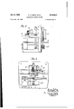
2 Fig, 2 shows a side view partly diagrammatic, of the eddy currentimotor apparatus,.and
Fig.- 3 shows a similar irontview of said appa-- ratusr.
l is a pair. of switch contacts connected to the; poleL of the supply mainssL N, and-whichi-are A closed by; say,--.anelectromagnet lawhen the.
primary currentflows in. its energising. winding-.,.. It will be well .known that various formsof ap-.
paratus are. known to .eifectthispurpose and...
which may-be considered as relays. None ..is-.
therefore described because it will be. so .well
known.
An eddy. current motor of the watt-hour meter.
type comprises .a usualdisc .2 of conducting.ma-.
terial acted upon. bya voltage magnet-3 and two currentmagnetSA, 5, which urge it in opposite directions. Thisdisc drivesthrough gearing 6 a disc '1 which. carries a pint! whose movement in one direction will'close contacts 9 and whose movement: in..the opposite direction will close contacts It. -The disc I carriesa magnetic armature I l which co-operates with either an elec: l
tro-magnet l2 or an electro-magnet I'Bdepending' The on the directionof rotation of the disc I. arrangement. of this part of the apparatus is such that when. the. pin 8 is moving. towards the contacts-9, the magnet 12 is energised and attracts the armature II so as to provide additional force actin to close the contacts. vWhen the disc 1 moves in the opposite .direction and the pin -8 moves towards the contacts ID the magnet l3-is energised and the armature H is attracted so as to provide additionalforce acting to closesaid contacts H3. -The energisation-of the magnet 4 causes the disc .1 to rotate to move 1 the .pin 8 away from the contacts 9 and towards the contacts It], and the energisation of the 'magnet .5 causes the .disc 1 to rotate in the opposite. direction to move the pin 8 towards the contacts 9. The vmagnetswl and. 5 are so proportioned that the. magnet 5 causes the discs 2 and! to rotate faster than does the'magnet 4.
The contacts I are connected in the circuitof a relay I l. The circuit of that relay .will be closedfor the intervals during which thecontacts.
l are closed, thatis, the intervals during which Whenthe relay l4 the. primary current flows. is energisedit operates the front contacts of the contact set l5 so as'to connect themagnet 4 in' circuit with the supplytransformer IBthrough the variable resistance I7. the set l5 keep the resistance I! in circuit with the secondary of the. transformer [6 when the relay. I4 is de-energised and thus maintain the. p
The back contacts of.
ladand hence the voltageacross the secondary substantially constant during operation of the apparatus. The back contacts of the set 22 perform a similar function in respect of the resistance 29 (referred to below). The magnet 4 is then energised and the disc 1' moves the pin 8 away from the contacts 9 and towards the contacts In.
In the arrangement shown in the drawings, the magnet 4 is permanently energised through a variable resistance Ila, which is preferably of a value high in relation to the resistance 8'! and serves as a creep adjustment when the apparatus is used, say, in connection with fuel feed mechanism in a furnace. Its purpose is to provide for a "trickle feed of fuel to the furnace to compensate for the inevitable in-leakage of air to the furnace which would otherwise upset the correct air/fuel ratio. In other applications of the apparatus, however, the creep adjustment resistance Ila may be omitted.
When the contacts In are closed by the pin 8, the relay I9 is energised and efiects a number of energizing or de-energizing operations through. a series of contacts. Firstly, it closes the contacts 20 and thereby produces a hold-on of the coil of the relay I9 after the switch 18 is opened, as described below. It will be noted that contacts 28 are in series with contacts 2! which at this stage are closed. Secondly it changes over the contacts 22 so as to connect the magnet to the sup-ply transformer I6 through the variable resistance 29. This causes the disc 2 and consequently the disc I to rotate in the opposite direction so as to move the pin 8 towards the contacts 9. If the relay I4 is still energised the speed of the discs will be the difference of speed produced by the two magnets 4, 5. Thirdly it operates the contacts 23 so as to disconnect the magnet [3 from and connect the magnet i2 to the supply transformer I6 whereby when the armature H moves towards said magnet an additional force will be provided to move the pin 8 to close the contacts 9. Fourthly it operates the contacts 24 which control circuits 0G of indicating means such as lamps which will show when the relay I9 is energised or not and therefore when the secondary circuit is closed or not. Fifthly it operates the contacts 25 which close the secondary circuit 26 to be controlled, i. e., in which the secondary current is to flow. Sixthly it closes the contacts 21 in the circuit of a third relay 28 and the contacts 9, so that immediately the pin 8 closes the contacts 9 the relay 28 is energised and the contacts 2| which it controls are immediately opened. As these are in series with the contacts 20 the relay I9 is immediately deenergised and all the contacts which it controls open. Thus the secondary circuit is broken. The contacts 21 open and the relay 28 becomes de-energised even though the contacts 9 remain closed. A modifying control of the time ratio between the period of duration of the primary impulses and that during which the secondary circuit remains closed is provided by a clock-operated switch, designated generally at E3, which is continuously running and which may be a synchronous motor. This switch consists of a slip-ring on the motor shaft connected by a brush to the supply main N and electrically connected to a conducting segment in an insulating ring also fixed on the motor shaft. A brush bears on the insulating ring and every time the conducting segment passes under it transmits a current impulse to the relay l9, which then operates the contacts 25 to close the secondary circuit 26, without the delay attendant on the closing of the contacts Ill by the pin 8. The secondary circuit remains closed until the disc 2 has run back under the action of the magnet -5, energised by the contacts 22 of the relay I9, far enough to bring about closure of the contacts 9 by the pin 8. Should the switch l8 again close before a primary current impulse in the magnet la. operates the relay I4 to energise the magnet 4 and drive the disc forward, the relay l9 will only be energised momentarily since the pin 8 will be resting against the contacts 9 and will be drawn round to hold them closed due to the attraction of the armature II by the coil 12 energised by closure of the contacts 23 of the relay Hi. In a typical. apparatus according to the invention the speed of rotation of the switch I8 is about 1 R. P. M.
Should the switch l8 be omitted it will be realised that only the magnet 4 will become energised at intervals and this will cause the disc 1 to rotate so as to move the pin 8 in steps until the contacts I 0 are closed. The closing of the contacts ID will effect the same purpose as the switch IS in that the relay coil l9 will be energized and the series of energising and de-energising operations described above will take place. During these operations the secondary circuit will be closed until the pin 8 closes the contacts 9. Thus it will be seen that the switch 18 may be dispensed with. However, this switch 18 causes the closing of the secondary circuit at regular convenient intervals. If desired the speed of the motor driving the switch l8 may be arranged to be variable, so that the modifying ontrol to be exercised thereby may be elected according to the prevailing conditions of the process or operations regulated by the secondary circuit 26. It may be noted here that, if the contacts l are short-circuited, the apparatus can be used as a master time controller.
The time during which the magnet 4 is energised is the time that the primary current is flowing through the electro-magnet la to operate the contacts I, whilst the time during which. the magnet 5 is energised is the time that the secondary circuit is closed and is also the time that the pin 8 is moving towards the contacts 9. In a condition therefore in which the magnet 4 is alone energised and then the magnet 5 is alone energised the time of the movement of the pin 8 towards the contacts 9 is a definite fraction of the time of movement of the pin away from said contacts. Therefore the secondary circuit is closed for this definite fraction of time that the primary current flows. The speed of the disc 2 depends on the strengths of the magnets 4, 5, that is on the currentwhichfiows in the magnetising coils of said magnets. Thus the fraction of time that the primary current flows and which is the time that the secondary circuit is closed can be controlled by varying the magnetising current of the magnets 4 and 5 by means of the variable resistances I! and 29.
However, for part of the time both magnets 4 and 5 may be energised together. The result will be that the time during which the pin 8 moves towards the contacts 9 will be increased because the magnet 4 is tending to drive the pin in the opposite direction for a part of the time. The disc 2 has the effect of adding together the time periods during which primary current flows and the fractions of this sum during which the secondary circuit is to be closed, in conditions in which magnetsd and'5 are energised either together" orseparately; l
Insteadof two'sep'arate'magnets 4,5 a single centre'tappedcoil may be'employed.
The 'disc 1" may be replaced byan arm, as will magnet when the primary electrical current impulses flow, means tocause energisation of the other-mdgnetat predetermined intervals comprising contacts closed by-the movable element of the motor under the action of the one magnet,'means to cause de-energisation-of said other magnet when the movable element of the motorhas returned to a zero or starting position, and
means to close the secondary circuit during the periodthat the'movable' element of the'motor is returning to the'zero or starting position, said other magnet causing the movable element to move at a faster rate than does the'one' magnet.
2. An electrical timingdevice of the kind to receiveprim'ary electrical current impulses from a first electrical circuit which act to close a secondary electrical circuitincluding apparatus to be controlled, for a period 'oftime'which' is a desired-fraction of the duration of the primaiy impulses, the saidtimin device comprising an electric eddy-currentmotor of the watt hour meter" type having two currentmagnets which act on the movable element to urge it in opposite directions, a relay 'which is energised when the-primary electrical currentimpulsesflow, contacts conn'ectedin the circuit of one magnet and controlled by the relay; means to cause energi cation of the other magnet at predetermined intervals comprising contactsclosed by the movable-element of the motorunder the action of the one magnet, means to cause de-energisation of said other magnet when the movable element of themotor has returned toa zero or starting position, and'means to close the secondary circuit during the period that the movable'elementof the motor is returning to the-'zero or starting position,- said othermagnet' causing the movable element to move at'a faster-rate than does the one magnet.
3. An electrical timing device'of the kind to receive primary electrical currentimpulses from a first electrical circuit which act to close a secondary electrical circuit including apparatus to be controlled, for a period of desired fraction of theduration of the-primary impulses, the said timing device comprising an electric eddy-current motor of the watt-hour me ter type having two current magnets which act on the movable element to urge it in opposite directions, a first relay to cause energisation of one magnet when the primary electrical current impulses flow, means to cause energisation of the other magnet at predetermined intervals comprising a second relay, contacts in the circuit of the second relay, closed by the movable element of the motor under the action of the one magnet, contacts controlled by the second relay and "time which is a in the circuit of *theother magnet, means-to said-other magnetwhen'" themovable elementof the motor has returned cause de-energisation of to azero or starting position; and means to close the secondary circuit during the" period that the movable element of the motor is returning to the zero or starting=position, said other magnet causingthe movable element to move at a faster rate than does'theone magnet.
" 4. An electrical timing device of the kind to receive primary electrical current impulses from a tacts connected in the circuit of one magnet and' means'to cause en- I ergisatio-n of the other magnet at predetermined intervals comprising a second relay, contacts in controlled by'the first relay,
the circuit of the second relay closed by the movable-element of the motor under the action of the'one magnet, contacts controlled by the secand relay-and in the circuit of the other magnet, means to cause de-energisation of said other magnet when the movable element of the motor hasreturned to a zero or starting position," and to close the period that the movable element of the motor is returning to the-zero or starting position; said other magnet causing the movable elementto move at a faster rate than does the one'magnet.
5. An electrical timing device of the-kind to receive primary electrical current-impulses from a first electrical circuit cndary electrical circuit including apparatus to be controlled-for a period of time which'is a C16? sired fraction of the duration of the primary impulses, the said timing device comprising an elec" tric eddy-current motor of the watt-hour meter type having two current magnets which act on the movable element to urge it in opposite dia first relay which is energised when the primz-rryw electrical current impulses fiowyconrections,
tacts connected in the circuit of one magnet and controlled by the first relay, means to cause energisation of the other magnet at predetermined intervalsficomprising a second relay, contacts in the circuit of the second relay closed by the movable eIement of the motor under. the action of the one magnet, contacts controlled by the sec:
ond relay and in the circuitof the other mag: net, contacts in the circuit of the second relay,. a
contacts, contacts in the circuit of the third relay which are closed by third relay to open saidthe movable element of=the motor when it returnsto its zero orstarting positiom-and -means to close the secondary circuit-during'the periodelement of-the motor is returning to thezero or starting position saidl other magnet causingthe movable element 1 to i-move" at a faster rate than does the one magnet.
6. An electrical timing device of the kind to receive primary electrical current impulses from a first electrical circuit which act to close a secondary electrical circuit including apparatus to be controlled, for a period of time which is a desired fraction of the duration of the primary impulses according to claim 5 wherein the means secondary circuit during the which act to close a secto close the secondary circuit comprises contacts controlled by the second relay.
'7. An electrica1 timing device of the kind to receive primary electrical current impulses from a first electrical circuit which act to close a secondary electrical circuit including apparatus to be controlled, for a period of time which is a desired fraction of the duration of the primary impulses, the said timing device comprising an electric eddy-current motor of the watt-hour meter type having two current magnets which act on the movable element to urge it in opposite directions, a variable resistance in the circuit of each of the current magnets, a first relay which is energised when the primary electrical current impulses flow, contacts connected in the circuit of one magnet and controlled by the first relay, means to cause energisaticn of the other magnet at predetermined intervals comprising a second relay, contacts in the circuit of the second relay closed by the movable element of the motor under the action of the one magnet, contacts controlled by the second relay and in the circuit of the other magnet, contacts in the circuit of the second relay, a third relay to open said contacts, contacts in the circuit of the third relay which are closed by the movable element of the motor when it returns to its zero or starting position, and means to close the secondary circuit during the period that the movable element of the motor is returning to the zero or starting position, said other magnet causing the movable element to move at a faster rate than does the one magnet.
8. Apparatus according to claim 1 wherein the one magnet is directly connected to supply terminals through a resistance.
9. Apparatus according to claim 1 wherein the other magnet is directly connected to supply terminals through a resistance.
10. An electrical timing device of the kind to receive primary electrical current impulses from a first electrical circuit which act to close a secondary electrical circuit including apparatus to be controlled for a period of time which is a desired fraction of the duration of the primary impulses, the said timing device comprising an electric eddy-current motor of the watt-hour meter type having two current magnets which act on the movable element to urge it in opposite directions, means to cause energisation of one magnet when the primary electrical current impulses flow, means to cause energisation of the other magnet at predetermined intervals comprising time-switch mechanism and contacts closed by the movable element of the motor under the action of the one magnet, means to cause deenergisation of said other magnet when the movable element of the motor has returned to a zero or starting position, and means to close the secondary circuit during the period that the movable element of the motor is returning to the zero or starting position, said other magnet causing the movable element to move at a faster rate than does the one magnet.
11. An electrical timing device of the kind to receive primary electrical current impulses from a first electrical circuit which act to close a secondary electrical circuit including apparatus to be controlled, for a period of time which is a desired fraction of the duration of the primary impulses, the said timing device comprising an electric eddy-current motor of the watt-hour meter type having two current magnets which act on the movable element to urge it in opposite directions, a first relay which is energised when the primary electrical current impulses flow, contacts connected in the circuit of one magnet and controlled by the first relay, means to cause energisation of the other magnet at predetermined intervals, comprising time switch mechanism, a second relay, contacts in the circuit of the second relay closed by the movable element of the motor under the action of the one magnet, other contacts in the circuit of the second relay in parallel with the first contacts and closed by the time switch mechanism, contacts controlled by the second relay and in the circuit of the other magnet, means to cause de-energisation of said other magnet when the movable element of the motor has returned to a zero or starting position, and means to close the secondary circuit during the period that the movable element of the motor is returning to the zero or starting position, said other magnet causing the movable element to move at a faster rate than does the one magnet.
12. An electrical timing device of the kind to receive primary electrical current impulses from a first electrical circuit which act to close a secondary electrical circuit including apparatus to be controlled, for a period of time which is a desired fraction of the duration of the primary impulses, the said timing device comprising an electric eddy-current motor of the watthour meter type having two current magnets which act on the movable element to urge it in opposite directions, a first relay which is energised when the primary electrical current impulses fiow, contacts connected in the circuit of one magnet and controlled by the first relay, means to cause energisation of the other magnet at predetermined intervals, comprising time-switch mechanism, a second relay, contacts in the circuit of the second relay closed by the movable element of the motor under the action of the one magnet, other contacts in the circuit of the second relay in parallel with the first contacts and closed by the time-switch mechanism, contacts controlled by the second relay and in the circuit of the other magnet, contacts in the circuit of the second relay, a third relay to open said contacts, contacts in the circuit of the third relay which are closed by the movable element of the motor when it returns to its zero or starting position, and means to close the secondary circuit during the period that the movable element of the motor is returning to the zero or starting position, said other magnet causing the movable element to move at a faster rate than does the one magnet.
CECIL HILL SMITH. HERMAN LINDARS.
Applications Claiming Priority (1)
| Application Number | Priority Date | Filing Date | Title |
|---|---|---|---|
| GB2444619X | 1944-09-14 |
Publications (1)
| Publication Number | Publication Date |
|---|---|
| US2444619A true US2444619A (en) | 1948-07-06 |
Family
ID=10907103
Family Applications (1)
| Application Number | Title | Priority Date | Filing Date |
|---|---|---|---|
| US613656A Expired - Lifetime US2444619A (en) | 1944-09-14 | 1945-08-30 | Electrical timing device |
Country Status (1)
| Country | Link |
|---|---|
| US (1) | US2444619A (en) |
Cited By (1)
| Publication number | Priority date | Publication date | Assignee | Title |
|---|---|---|---|---|
| US2553354A (en) * | 1948-04-23 | 1951-05-15 | Standard Oil Dev Co | Sensitive relay |
-
1945
- 1945-08-30 US US613656A patent/US2444619A/en not_active Expired - Lifetime
Non-Patent Citations (1)
| Title |
|---|
| None * |
Cited By (1)
| Publication number | Priority date | Publication date | Assignee | Title |
|---|---|---|---|---|
| US2553354A (en) * | 1948-04-23 | 1951-05-15 | Standard Oil Dev Co | Sensitive relay |
Similar Documents
| Publication | Publication Date | Title |
|---|---|---|
| US2218502A (en) | Temperature controller | |
| US2444619A (en) | Electrical timing device | |
| US2677800A (en) | Electrical control device | |
| US2371236A (en) | Control device | |
| US2108775A (en) | Relay | |
| US2731626A (en) | carolus | |
| US1650889A (en) | System of regulation | |
| US2428403A (en) | Antiarcing electric motor control apparatus | |
| US1015968A (en) | Alternating-current electromagnet. | |
| US2454671A (en) | Electric motor control | |
| US1979311A (en) | System of measurement and control | |
| US2132277A (en) | Control system | |
| US2383942A (en) | Automatic electrical control means | |
| US1606571A (en) | Relay | |
| US2016144A (en) | Electrical circuit | |
| US2487714A (en) | Progressive illuminating means | |
| US2671190A (en) | Electric motor control means | |
| US2530214A (en) | Apparatus for comparing the rates of operation of two contact devices | |
| US1283329A (en) | Electromagnetic apparatus. | |
| US2947919A (en) | Circuits for contact meters | |
| US2093582A (en) | Temperature regulator | |
| US2587441A (en) | Device for controlling consumer circuits by means of at least one measuring instrument carrying small currents | |
| US2296031A (en) | Voltage regulating apparatus | |
| US1919991A (en) | Electroresponsive time element device | |
| US2403669A (en) | Inductor compasss |