US2430733A - Device for removing tubes from heat exchange assemblies - Google Patents
Device for removing tubes from heat exchange assemblies Download PDFInfo
- Publication number
- US2430733A US2430733A US521485A US52148544A US2430733A US 2430733 A US2430733 A US 2430733A US 521485 A US521485 A US 521485A US 52148544 A US52148544 A US 52148544A US 2430733 A US2430733 A US 2430733A
- Authority
- US
- United States
- Prior art keywords
- tube
- tool
- heat exchange
- tubing
- blade
- Prior art date
- Legal status (The legal status is an assumption and is not a legal conclusion. Google has not performed a legal analysis and makes no representation as to the accuracy of the status listed.)
- Expired - Lifetime
Links
- 230000000712 assembly Effects 0.000 title 1
- 238000000429 assembly Methods 0.000 title 1
- 238000005520 cutting process Methods 0.000 description 12
- 238000000034 method Methods 0.000 description 3
- 241001647090 Ponca Species 0.000 description 2
- 238000010276 construction Methods 0.000 description 1
- 238000004519 manufacturing process Methods 0.000 description 1
- 239000002184 metal Substances 0.000 description 1
Images
Classifications
-
- B—PERFORMING OPERATIONS; TRANSPORTING
- B25—HAND TOOLS; PORTABLE POWER-DRIVEN TOOLS; MANIPULATORS
- B25B—TOOLS OR BENCH DEVICES NOT OTHERWISE PROVIDED FOR, FOR FASTENING, CONNECTING, DISENGAGING OR HOLDING
- B25B27/00—Hand tools, specially adapted for fitting together or separating parts or objects whether or not involving some deformation, not otherwise provided for
- B25B27/02—Hand tools, specially adapted for fitting together or separating parts or objects whether or not involving some deformation, not otherwise provided for for connecting objects by press fit or detaching same
-
- Y—GENERAL TAGGING OF NEW TECHNOLOGICAL DEVELOPMENTS; GENERAL TAGGING OF CROSS-SECTIONAL TECHNOLOGIES SPANNING OVER SEVERAL SECTIONS OF THE IPC; TECHNICAL SUBJECTS COVERED BY FORMER USPC CROSS-REFERENCE ART COLLECTIONS [XRACs] AND DIGESTS
- Y10—TECHNICAL SUBJECTS COVERED BY FORMER USPC
- Y10T—TECHNICAL SUBJECTS COVERED BY FORMER US CLASSIFICATION
- Y10T29/00—Metal working
- Y10T29/53—Means to assemble or disassemble
- Y10T29/53909—Means comprising hand manipulatable tool
- Y10T29/5393—Means comprising impact receiving tool
-
- Y—GENERAL TAGGING OF NEW TECHNOLOGICAL DEVELOPMENTS; GENERAL TAGGING OF CROSS-SECTIONAL TECHNOLOGIES SPANNING OVER SEVERAL SECTIONS OF THE IPC; TECHNICAL SUBJECTS COVERED BY FORMER USPC CROSS-REFERENCE ART COLLECTIONS [XRACs] AND DIGESTS
- Y10—TECHNICAL SUBJECTS COVERED BY FORMER USPC
- Y10T—TECHNICAL SUBJECTS COVERED BY FORMER US CLASSIFICATION
- Y10T407/00—Cutters, for shaping
- Y10T407/16—Rectilinear broach
Definitions
- My invention relates to new and useful improvements in tube extractors.
- An important object of my invention is to provide a tool that will quickly and efliciently remove the stub sections of tubing from the tube sheets.
- Another object of my invention is to provide a tool of the above mentioned character that will split the sections of tubing and drive them from the tube sheet in one continuous operation.
- Still another object of my invention is to provide a tube extractor that will not cut or otherwise damage the tube sheet during removal of the tube sections.
- Yet another object of my invention is to provide a tube extractor tool that is simple in construction and inexpensive to manufacture.
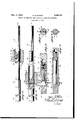
- Fig. 1 is a side elevation of a tube extractor tool embodying my invention and showing the manner in which a, stub section of tubing is split longitudinally, parts of the tool being broken away and shown in section for clearness of illustration,
- Fig. 2 is a side elevation of the tool showing the manner in which split sections of tubing are driven from the tube sheet, parts of the tool being broken away and shown inl section.
- Fig. 3 is a fragmentary longitudinal sectional view taken along the line 3 3 of Fig. 2,
- Fig. 4 is a transverse sectional view taken on the line 4 4 of Fig. 3,
- Fig. 5 is a longitudinal sectional View of a modied form of the invention.
- Fig. 6 is a transverse sectional View taken on the line 6--6 of Fig, 5.
- the tool embodying my invention is formed at one end with an elongated cylindrical guide portion lwhich snugly lits within the tubeY section to be removed.
- the guide is inserted vin the tube section to properly center and locate cutting blades which project radially from the ⁇ body.
- the tool is adapted to conf 1 neet with a pneumatic hammer which is operated to drive the cutting blades through the tube and split it longitudinally.
- the guide centers the tool and prevents the blades from cutting or otherwise 'damaging the tube sheet.
- the tool itself, is centered within the tubing during the cutting operation by a cylindrical guide I4 threaded on the forward end of body I0 and adapted to fit snugly but slidably within the tubing I I.
- guide I4 is formed at its inner end with a socket Illa which accommodates the project-v ing head portion of bolt I5.
- the cutting edges of blade I3 split the tube longitudinally.
- the narrow strips of metal IIa cut Y from the tubing are accommodated with cavities or recesses Illb formed in the body in advance of the cutting blade.
- the lower edges of the projecting cutters are arcuately curved, as at I3c, to direct strips I Ia into the recesses.
- the tube section After the tube section has been longitudinally split it can -be easily collapsed and driven from tube sheet I2. This is done by a driving sleeve I6 removably mounted on body I0 behind blade 4 passed through the tube section it is collapsed by the driving sleeve I8 and driven from the tube the cuttingbladeso that-the cutting operation is completed v"before the sleeve engages thetubesec-E.
- the driving sleeve is removably lretained on the bodyby a detent I1 mounted in a socket Icformed in the body behind the sleeve.
- a spring I8 normally urges the detentli'nto' *aregisteringmw opening IBc in sleeve I 6,
- the tool can be driven to remove vthe tube sec? modate a pneumatic .hammer.
- the body III should ⁇ be of :lesser diameter than the smallest size tube -for which the tool is tobe from a tube sheet comprising a body adapted to used.
- cutting' blade I3, guide I4 and driving 'sleeve I6 must be accuratelydimensloned withrespect to the Yparticulartube to be removed,-
- Blader I3 must accuratelyilt the outsidefdiaineter of. the tube..
- tube extractor for removing tube sections pass throughthe tube to' be extracted
Landscapes
- Engineering & Computer Science (AREA)
- Mechanical Engineering (AREA)
- Perforating, Stamping-Out Or Severing By Means Other Than Cutting (AREA)
Description
Nov. 11, 1947. F. M. PAxsoN DEVICE FOR REMOVING TUBES FROM HEAT EXCHANGE ASSEMBLIES Filed Feb. 7, 1944 INVENTOR. M /xo/y A from/EK Patented Nov. 11, 1947 DEVICE FOR REMOVIN G TUBES FROM HEAT EXCHANGE ASSEMBLIES Frank M. AParson, Ponca City, Okla., assigner to Continental Oil Company, Ponca City, Okla., a corporation of Delaware Application February 7, 1944, Serial No. 521,485
1 Claim.
My invention relates to new and useful improvements in tube extractors.
The tubes in heat exchange equipment rapidly become worn or corroded and require frequent replacement. However, theirreplacement is a tedious procedure since the ends of the tubes fit tightly in the tube sheets and are very diflicult to remove.
The usual procedure is to cut the tubes transversely just outside of the tube sheets and then drive out each stub section of tubing with a suitable plug after the section has been weakened and loosened by manually splitting it with a gouge. However, this method is slow and tedious. Furthermore, it is ine'icient since the tube sheets are frequently damaged by the gouge when the stub sections are split.
An important object of my invention is to provide a tool that will quickly and efliciently remove the stub sections of tubing from the tube sheets.
Another object of my invention is to provide a tool of the above mentioned character that will split the sections of tubing and drive them from the tube sheet in one continuous operation.
Still another object of my invention is to provide a tube extractor that will not cut or otherwise damage the tube sheet during removal of the tube sections.
Yet another object of my invention is to provide a tube extractor tool that is simple in construction and inexpensive to manufacture.
Other objects and advantages of my invention will be apparent during the course of the following description.
In the drawing forming a part of this specification and wherein like numerals are employed to designate like parts throughout the same,l
Fig. 1 is a side elevation of a tube extractor tool embodying my invention and showing the manner in which a, stub section of tubing is split longitudinally, parts of the tool being broken away and shown in section for clearness of illustration,
Fig. 2 is a side elevation of the tool showing the manner in which split sections of tubing are driven from the tube sheet, parts of the tool being broken away and shown inl section.
Fig. 3 is a fragmentary longitudinal sectional view taken along the line 3 3 of Fig. 2,
Fig. 4 is a transverse sectional view taken on the line 4 4 of Fig. 3,
Fig. 5 is a longitudinal sectional View of a modied form of the invention, and
Fig. 6 is a transverse sectional View taken on the line 6--6 of Fig, 5.
In brief,V the tool embodying my invention is formed at one end with an elongated cylindrical guide portion lwhich snugly lits within the tubeY section to be removed. The guide is inserted vin the tube section to properly center and locate cutting blades which project radially from the` body. At its other end the tool is adapted to conf 1 neet with a pneumatic hammer which is operated to drive the cutting blades through the tube and split it longitudinally. During the splitting operation the guide centers the tool and prevents the blades from cutting or otherwise 'damaging the tube sheet. After the section of tubing has been split it is easily collapsed and driven fromathe sheet by an annular shoulder formed on the 'tool'V dia-metric slot IIJa at substantially the middle'of v the body I0. The Widthof the blade lssubstantially equal to the outside diameter of the tubing II and its projecting ends-are formed with-cutting edges I3a which slice longitudinal strips from the tubing when the tool is driven therethrough*l Formed on the blade are rearwardly projecting arms I3b which embrace body I0 holding the blade properly centered in slot Illa and preventing the blade from shifting laterally within the slot and cutting into the tube sheet. Bolt I5 extending longitudinally through the forward end of the body presses against blade I3, and holds it securely within the slot. The tool, itself, is centered within the tubing during the cutting operation by a cylindrical guide I4 threaded on the forward end of body I0 and adapted to fit snugly but slidably within the tubing I I. As best shown in Fig. 3, guide I4 is formed at its inner end with a socket Illa which accommodates the project-v ing head portion of bolt I5.
As the tool is driven through tubing II, the cutting edges of blade I3 split the tube longitudinally. The narrow strips of metal IIa cut Y from the tubing are accommodated with cavities or recesses Illb formed in the body in advance of the cutting blade. As best shown in Fig. 3 the lower edges of the projecting cutters are arcuately curved, as at I3c, to direct strips I Ia into the recesses.
After the tube section has been longitudinally split it can -be easily collapsed and driven from tube sheet I2. This is done by a driving sleeve I6 removably mounted on body I0 behind blade 4 passed through the tube section it is collapsed by the driving sleeve I8 and driven from the tube the cuttingbladeso that-the cutting operation is completed v"before the sleeve engages thetubesec-E.
tion. The driving sleeve is removably lretained on the bodyby a detent I1 mounted in a socket Icformed in the body behind the sleeve. A spring I8 normally urges the detentli'nto' *aregisteringmw opening IBc in sleeve I 6,
The tool can be driven to remove vthe tube sec? modate a pneumatic .hammer.
The body III should `be of :lesser diameter than the smallest size tube -for which the tool is tobe from a tube sheet comprising a body adapted to used. However, cutting' blade I3, guide I4 and driving 'sleeve I6 must be accuratelydimensloned withrespect to the Yparticulartube to be removed,-
Guide .llemust snugly fit within the tube, section toi-properly center thetool andprevent thebladel I3 fromgcuttingfinto thetube sheet. Blader I3 must accuratelyilt the outsidefdiaineter of. the tube.. The strips cut from 'thetubetmust vbe subs; stantially. its -fullgthicknessgso thatit ycan be prop -Y erly collapsed and ,driven from the tube vsheet Ab y sleeve. I6...1 Obviously, sleeve V,I6 must accurately,
fit the tube if it istoeiliciently drivel it from 'the sheet. According- 151,1 havemade parts 14,. I3 and Iremcvable so that .elements can-#be attached.' to the body which properly fltthe particular tube.,
sectiontoberernovedn. l
Referring now to the form ci .the .invention illustrated in Figs. ,l5 and, .,I, have here vshown the Acutting blade I3 ,and retaining bolt, I .5 replaced `tion in any suitable manner; however, I prefer v that the end 10d ofthe body be shaped to accom` sheet.
It may thus be seen that I have achieved the objects of my invention. I have provided a tube extractor-that will rapidly and eiilcientlyremove tube s ect'iors` fromfa tube sheet in a single continuous operation and without cutting or otherwise damaging the tube sheet.
It is to be vunderstood that the forms of the invention'herewith shown and described are to be taken'as preferred examples of the same and that various changes in the size, shape and arrangement ofparts may be resorted to without departing. fromgthe spirit of my invention or the scope of the appendedclaim.
Having thus described my invention, I claim: A, tube extractor for removing tube sections pass throughthe tube to' be extracted| a cuttine blade of' a width equal to the outer Vdiameter of saidtubecarried by'said body and extending radially .therefrom whereby such tube is axially divided as said body is driven therethrough, an exthe usualjtubesheet, said shoulder being of a radial cutting: blades Y I 9a. f Asbest lshown in Fig.,
5 the blades graduallyincrease vinwidth toward the rearward or upper yend A.of thesleeve. The
sleeve IISisretainedbetween an annular shoulder I'eormedon Vthefpcidy. and the ladjacent end ci,
thin-strips --from the tubev section fa's the'e, tcol isf.
driven.' therethrough. After. the. blades have diameterto substantially fit said tube sheet so that saidshoulder will engage the forward endv of theftube operated upon after saidkblade has Passed 'through Such tube.
;Y Y FRANK M. PAXsoN.
REFERENCES CITED The following references are of vrecord in the le of this patent: 4
` UNITED VSTATES PATENTS Number `Name Date 1,370,837 Perkins et al. I Mar. 8, 1921 1,432,411)` Oakley Oct. 17, 1922 2,215,616 Lapointe et al Sept. 24, 1940 ...689,742 Newman Dec. 24, 1901 2,176,626 Gentry 1 Octl?, 1939 1,276,458A AWagner Aug. 20, 1918 1,471,062 vRiblett Oct. 16, 1923
Priority Applications (1)
| Application Number | Priority Date | Filing Date | Title |
|---|---|---|---|
| US521485A US2430733A (en) | 1944-02-07 | 1944-02-07 | Device for removing tubes from heat exchange assemblies |
Applications Claiming Priority (1)
| Application Number | Priority Date | Filing Date | Title |
|---|---|---|---|
| US521485A US2430733A (en) | 1944-02-07 | 1944-02-07 | Device for removing tubes from heat exchange assemblies |
Publications (1)
| Publication Number | Publication Date |
|---|---|
| US2430733A true US2430733A (en) | 1947-11-11 |
Family
ID=24076910
Family Applications (1)
| Application Number | Title | Priority Date | Filing Date |
|---|---|---|---|
| US521485A Expired - Lifetime US2430733A (en) | 1944-02-07 | 1944-02-07 | Device for removing tubes from heat exchange assemblies |
Country Status (1)
| Country | Link |
|---|---|
| US (1) | US2430733A (en) |
Cited By (6)
| Publication number | Priority date | Publication date | Assignee | Title |
|---|---|---|---|---|
| US2586222A (en) * | 1950-01-17 | 1952-02-19 | Hamilton Tool Co Inc | Bushing replacer |
| US2596549A (en) * | 1950-01-21 | 1952-05-13 | Hamilton Tool Co Inc | Multiple bushing replacer |
| US2651768A (en) * | 1947-04-02 | 1953-09-08 | Oortgijsen Jan | Electrical terminal having conductor-severing edge |
| US2983989A (en) * | 1959-07-06 | 1961-05-16 | Charles E Frantz | Broaching and tube-installing apparatus |
| US4619027A (en) * | 1985-02-25 | 1986-10-28 | Ohannesian Michael J | Tool for installing and aligning camshaft bushings in internal combustion engines |
| US20100104390A1 (en) * | 2007-02-17 | 2010-04-29 | Hartmetall-Werkzeugfabrik Paul Horn Gmbh | Broaching tool, in particular keyway broaching tool |
Citations (7)
| Publication number | Priority date | Publication date | Assignee | Title |
|---|---|---|---|---|
| US689742A (en) * | 1901-07-03 | 1901-12-24 | William Newman | Tool. |
| US1276458A (en) * | 1917-06-20 | 1918-08-20 | Elbert Loyd Wagner | Tube-splitter. |
| US1370837A (en) * | 1919-02-24 | 1921-03-08 | Perkins Appliance Company | Broach |
| US1432410A (en) * | 1921-04-19 | 1922-10-17 | Oakley John | Broach |
| US1471062A (en) * | 1923-03-24 | 1923-10-16 | Victor T Riblett | Flue tool |
| US2176626A (en) * | 1938-08-11 | 1939-10-17 | Arthur E Gentry | Bushing remover |
| US2215616A (en) * | 1938-03-10 | 1940-09-24 | American Broach And Machine Co | Broach |
-
1944
- 1944-02-07 US US521485A patent/US2430733A/en not_active Expired - Lifetime
Patent Citations (7)
| Publication number | Priority date | Publication date | Assignee | Title |
|---|---|---|---|---|
| US689742A (en) * | 1901-07-03 | 1901-12-24 | William Newman | Tool. |
| US1276458A (en) * | 1917-06-20 | 1918-08-20 | Elbert Loyd Wagner | Tube-splitter. |
| US1370837A (en) * | 1919-02-24 | 1921-03-08 | Perkins Appliance Company | Broach |
| US1432410A (en) * | 1921-04-19 | 1922-10-17 | Oakley John | Broach |
| US1471062A (en) * | 1923-03-24 | 1923-10-16 | Victor T Riblett | Flue tool |
| US2215616A (en) * | 1938-03-10 | 1940-09-24 | American Broach And Machine Co | Broach |
| US2176626A (en) * | 1938-08-11 | 1939-10-17 | Arthur E Gentry | Bushing remover |
Cited By (7)
| Publication number | Priority date | Publication date | Assignee | Title |
|---|---|---|---|---|
| US2651768A (en) * | 1947-04-02 | 1953-09-08 | Oortgijsen Jan | Electrical terminal having conductor-severing edge |
| US2586222A (en) * | 1950-01-17 | 1952-02-19 | Hamilton Tool Co Inc | Bushing replacer |
| US2596549A (en) * | 1950-01-21 | 1952-05-13 | Hamilton Tool Co Inc | Multiple bushing replacer |
| US2983989A (en) * | 1959-07-06 | 1961-05-16 | Charles E Frantz | Broaching and tube-installing apparatus |
| US4619027A (en) * | 1985-02-25 | 1986-10-28 | Ohannesian Michael J | Tool for installing and aligning camshaft bushings in internal combustion engines |
| US20100104390A1 (en) * | 2007-02-17 | 2010-04-29 | Hartmetall-Werkzeugfabrik Paul Horn Gmbh | Broaching tool, in particular keyway broaching tool |
| US8434972B2 (en) * | 2007-02-17 | 2013-05-07 | Hartmetall-Werkzeugfabrik Paul Horn Gmbh | Broaching tool, in particular keyway broaching tool |
Similar Documents
| Publication | Publication Date | Title |
|---|---|---|
| US2380068A (en) | Oil seal puller | |
| US5318390A (en) | Tool for removing rivets | |
| US2686447A (en) | Stud extractor structure | |
| US1521265A (en) | Driving tool | |
| US2430733A (en) | Device for removing tubes from heat exchange assemblies | |
| RU2400349C2 (en) | Device for removal of packing plug | |
| US2853723A (en) | Rivet removing tool with cutting edges and impact surface | |
| US6511267B2 (en) | Tool for removing broken fittings | |
| US7093360B1 (en) | Method of removing boiler tubes | |
| US6514017B2 (en) | Core drill piloting system | |
| AU2015202201B2 (en) | Fastener removal socket | |
| US2847225A (en) | Tool holder and ejector | |
| US5012566A (en) | Drilling and expanding tool for removing carburetor seal plugs | |
| US2177979A (en) | Chuck | |
| US2372398A (en) | Rivet drill | |
| JP4990693B2 (en) | Split groove structure of collet for chuck | |
| US1968872A (en) | Internal wrench | |
| US4608738A (en) | Method and apparatus for removing spindles and needle bearings | |
| US2675570A (en) | Extensible rotary pipe or conduit cleaning portable device | |
| US1338576A (en) | Tire-tool | |
| US2087814A (en) | Drill and holder therefor | |
| US2427843A (en) | Boiler tube slitter | |
| US6761512B2 (en) | Tool for removing cut-off plastic pipe in a pipe socket and method of use | |
| US2653029A (en) | Tool handle | |
| US1627886A (en) | Valve tool |