US2430526A - Apparatus for inspecting tin plate or the like - Google Patents
Apparatus for inspecting tin plate or the like Download PDFInfo
- Publication number
- US2430526A US2430526A US597118A US59711845A US2430526A US 2430526 A US2430526 A US 2430526A US 597118 A US597118 A US 597118A US 59711845 A US59711845 A US 59711845A US 2430526 A US2430526 A US 2430526A
- Authority
- US
- United States
- Prior art keywords
- sheet
- scanner
- path
- cell
- series
- Prior art date
- Legal status (The legal status is an assumption and is not a legal conclusion. Google has not performed a legal analysis and makes no representation as to the accuracy of the status listed.)
- Expired - Lifetime
Links
- 239000005028 tinplate Substances 0.000 title description 10
- 238000007689 inspection Methods 0.000 description 44
- 230000007547 defect Effects 0.000 description 15
- 230000002950 deficient Effects 0.000 description 7
- 230000035945 sensitivity Effects 0.000 description 7
- 229910052754 neon Inorganic materials 0.000 description 6
- GKAOGPIIYCISHV-UHFFFAOYSA-N neon atom Chemical compound [Ne] GKAOGPIIYCISHV-UHFFFAOYSA-N 0.000 description 6
- 230000008859 change Effects 0.000 description 5
- 238000010276 construction Methods 0.000 description 5
- 239000000463 material Substances 0.000 description 5
- 238000002310 reflectometry Methods 0.000 description 5
- 239000011521 glass Substances 0.000 description 4
- 230000003287 optical effect Effects 0.000 description 4
- ATJFFYVFTNAWJD-UHFFFAOYSA-N Tin Chemical compound [Sn] ATJFFYVFTNAWJD-UHFFFAOYSA-N 0.000 description 3
- 239000011248 coating agent Substances 0.000 description 3
- 238000000576 coating method Methods 0.000 description 3
- 210000003414 extremity Anatomy 0.000 description 3
- 238000010304 firing Methods 0.000 description 3
- 230000001105 regulatory effect Effects 0.000 description 3
- 230000008439 repair process Effects 0.000 description 3
- 230000004044 response Effects 0.000 description 3
- 230000000007 visual effect Effects 0.000 description 3
- 239000000969 carrier Substances 0.000 description 2
- 230000003247 decreasing effect Effects 0.000 description 2
- 230000000694 effects Effects 0.000 description 2
- 238000005192 partition Methods 0.000 description 2
- 230000009467 reduction Effects 0.000 description 2
- 241001654412 Corchorus hirsutus Species 0.000 description 1
- 230000003321 amplification Effects 0.000 description 1
- 208000003464 asthenopia Diseases 0.000 description 1
- 239000002131 composite material Substances 0.000 description 1
- 238000010586 diagram Methods 0.000 description 1
- 239000000428 dust Substances 0.000 description 1
- 239000004744 fabric Substances 0.000 description 1
- 230000004313 glare Effects 0.000 description 1
- 230000006698 induction Effects 0.000 description 1
- 230000000977 initiatory effect Effects 0.000 description 1
- 235000007261 jackswitch Nutrition 0.000 description 1
- 238000012423 maintenance Methods 0.000 description 1
- 230000007246 mechanism Effects 0.000 description 1
- 239000002184 metal Substances 0.000 description 1
- 238000012986 modification Methods 0.000 description 1
- 230000004048 modification Effects 0.000 description 1
- 238000003199 nucleic acid amplification method Methods 0.000 description 1
- 230000008520 organization Effects 0.000 description 1
- 230000010355 oscillation Effects 0.000 description 1
- 238000013021 overheating Methods 0.000 description 1
- 230000011514 reflex Effects 0.000 description 1
- 230000000630 rising effect Effects 0.000 description 1
- 231100000241 scar Toxicity 0.000 description 1
- 239000007779 soft material Substances 0.000 description 1
- 210000003813 thumb Anatomy 0.000 description 1
- 238000011179 visual inspection Methods 0.000 description 1
- 239000002699 waste material Substances 0.000 description 1
Images


Classifications
-
- G—PHYSICS
- G01—MEASURING; TESTING
- G01N—INVESTIGATING OR ANALYSING MATERIALS BY DETERMINING THEIR CHEMICAL OR PHYSICAL PROPERTIES
- G01N21/00—Investigating or analysing materials by the use of optical means, i.e. using sub-millimetre waves, infrared, visible or ultraviolet light
- G01N21/84—Systems specially adapted for particular applications
- G01N21/88—Investigating the presence of flaws or contamination
- G01N21/89—Investigating the presence of flaws or contamination in moving material, e.g. running paper or textiles
Definitions
- a further object of the invention is the provicapable of satisfactorily detectin all the differsion of inspection apparatus of the character ent kinds of imperfections which occur in tin aforesaid adapted for commercial operation and plate, among which are blisters formed by the tin capable of performing its intended function even coating rising from the ferrou base, scale pits when the material being inspected is moving thru and scale streaks, that is, uncoated areas caused the apparatus at relatively high speed.
- variations in that light induced by Additional objects include the arrangement of changes in the normal reflectivity of the tinned the instrumentalities in that portion of the apsurface when a defect passes into the View of paratus in which the scanning or inspection of the cell are supposed to vary the output of the the tin plate is effected and which is herein latter and so afford, through the amplifying and termed the scanner in such manner as to miniindicating means, some suitable indication of the mize the number of light sources and photocells presence of the defect.
- Another object is the individual wiring of each photocell and accompanying amplifier therefor in a separate removable unit.
- Another object is the provision of means for counting the defective and perfect sheets, thus eliminating the present reckoners.
- Still another object is the provision of electrically actuated control means for returning the apparatus to normal operating condition following inspection and ejection of a defective sheet to thereby recondition it for the inspection of the ensuing sheet.
- the apparatus comprises the scanner and a feeding and an exit conveyor between which the scanner is disposed, so for convenience we will first describe the scanner from its mechanical and optical standpoints, then the conveyors and associated parts, and finall the electrical circuits and instrumentalities employed in conjunction with the scanner and the exit conveyor and for resetting the apparatus for inspection of the succeeding sheet after the preceding one has been rejected.
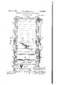
- Fig. 1 which is largely diagrammatic, is a fragmentary view of the upper half of the scanner with the casing removed and with parts broken away to better show others lying in subjacent planes;
- Fig. 2 on a much larger scale, is a vertical section thru the upper half of the scanner and a portion of the lower half below the plane of passage of the tinned sheets with certain parts shown in elevation;
- Fig. 3 is a composite view showing at the left a partially fragmentary side elevation of one end of the upper half of the scanner and at the right certain of the parts adjacent its opposite end as they would appear when viewed substantially on the plane of line 33 in Fig. 2 with the clamping yokes omitted;
- Fig. 4 on a much smaller scale than Figs. 2 and 3, is a fragmentary top plan detail of one of the shelf retaining yokes and adjacent parts;
- Fig 5 is a fragmentary somewhat diagrammatic side elevation of the inspection apparatus as a whole;
- Fig. 6 is a top plan View thereof
- Fig. '7 is a rear end View of the scanner and supporting frame
- Fig. 8 is a fragmentary section on line 88 in (Fig. 6 lOOking in the direction of the arrows; an
- Figs. 9 and 9a are schematic diagrams of electrical circuits and associated instrumentalities preferably employed in the apparatus.
- each series are arranged in reversed and staggered relation (Fig. 1), that is, in the first unit of the upper series, for example, the light source is disposed on one side of the vertical central plane of the scanner and the photocell actuated from the light emanating from that source on the opposite side thereof, whereas in the next adjacent unit the light source is on the same side of said plane as the photocell in the first unit and the cell on the opposite side.
- Fig. 1 the units of each series are arranged in reversed and staggered relation
- the scanner S comprises two heavy end plates I, I from which extend trunnions 2 on which it is supported as hereinafter described, As best shown in Figs. 1, 2 and 3, in each of its halves and extending between the end plates on opposite sides of its central transverse plane are side plates 3, 4 secured to the end plates and serving to support the photocells and associated amplifying means, while between these plates near their upper ends are disposed horizontal shelves 5 each of which respectively supports the light source 6, lens holder 1 and reflector 8 comprised in each unit. These shelves rest on supports 9 on the inner faces of the side plates and are removably held in place by yokes I 0 (Fig.
- the photoelectric cell 15 for each unit is supported in a suitable socket l6 extending thru whichever side plate is proximate light source 6 in that unit whereby the cell is in substantial vertical alignment with that source which is preferably an electric bulb of the straight line filament type so located that the filament extends transversely of the path of travel of the sheet.
- the beam from the source first passes thru a lens I!
- reflector 8 which is of black glass or other optically equivalent material as we have found that a reflector made of black glass when positioned so that the incident and reflected rays diverge at a maximum angle of substantially appears to exert an effect comparable to that of a polarizing filter when disposed in the path of the beam, and for reasons which we do not attempt to explain from a scientific standpoint so greatly increases the sensitivity of the unit that we regard the use of a reflector of black glass or its optical equivalent positioned as just described in the path of the ray between the light source and the sheet as essential or critical and thus one of the conditions requisite for satisfactory operation.
- the reflector 8 is so disposed as to theme direct the ray toward the sheet P at an angle approximating 15 to the vertical whence it is refiected at a similar angle thru a lens l8 and thence to photocell [5.
- Lens 18 is substantially rectangular in planary outline and is seated in an opening of suitable configuration in an elongated lens holder is secured to the adjacent side plate near its lower edge, a corresponding holder I 8' being oppositely disposed and secured to the other side plate to hold the lenses [8 which are located on that side of the scanner.
- These holders carry metal partitions it which are grooved to receive the ends of the lenses and also define the spaces 2
- a suitable thin metallic shield 22 is positioned over each cell to exclude any light therefrom save that passing thru the subjacent lens I8, the shield fitting snugly but removably between the partitions 2!] (Fig. 3).
- lens i1 is composed of double convex elements and it and reflector 3 are so arranged that ray R from the source will form an angle of approximately 115 with ray R, from the reflector to the point of incidence on the sheet while, as above stated, the reflected ray R" makes an angle of approximately 30 to ray R.
- 32 are disposed in sockets 33, 34, 35 carried by a vertically extending bracket 36 secured by a screw 31 to the side plate opposite that carrying the photocell, the lower end of the bracket being permanently attached to a plug 38 having a suitable number of prongs (not shown) registering with holes in a receptacle 39 seated on a conduit 4!] which parallels the side plate and houses the wires of the circuits in which the tubes are connected, these wires being appropriately connected to the parts in the receptacle with which the prongs in the plug are designed to register.
- the tubes, bracket and plug together with the other parts carried by the bracket and now to be described can be removed for replacement or repair without disturbing the brackets associated with the other units.
- each bracket above screw 31 is bent outwardly and finally downwardly to provide a horizontal portion forming a support for a pair of rheostats d2, 43 arranged in the tube circuits.
- Rheostat 42 is adapted for manual adjustment to suitably calibrate the tubes carried by the adjacent bracket, while the other rheostat 43 is mechanically interconnected with all the other corresponding rheostats in the upper part of the scanner so that all of them may be adjusted simultaneously in the same amount.
- This mechanical interconnection is effected thru the medium of two racks 44 extending proximate the upper edges of the side plates and provided with teeth on their outer faces meshing with small gears 46 on the rheostat shafts, each rack being alsoprovided near one end with teeth 41 on its upper surface engaging pinions 68 on a shaft. 49 extending thru and journaled in the side plates, one end of the shaft being extended oppositely outwardly and provided with a knurled head 50; thus by rotating the head in one direction or the other all rheostats 43 can be simultaneously adjusted.
- rheostat 42 is utilized to bring the set in which replacement has been made to the same calibration as the other sets.
- Conduits 53 are preferably associated with the upper portions of the plates to house the wires which supply current to light sources 6.
- a small neon light 55 is mounted in a suitable socket 56 in the outer downwardly turned extremity of each bracket and the removable casings 51 which respectively enclose the upper and lower parts of the scanner and are held in position with thumb screws 58 extending into end plates I are provided with small windows aligned with these bulbs so the light emitted therefrom will be visible from outside the casings.
- the latter are suitably slotted at their lower ends as at 59 to permit the passage of the sheets and their extremities fit snugly over the end plates and project at their free edges into sockets 60 carried thereby, the function of the casings being to exclude dust from the interior of the scanner.
- a small exhaust blower (not shown) may be attached to the casing to exhaust air therefrom and prevent overheating which might otherwise occur owing to the large number of lights within it.
- rollers 64 desirably ball bearing and faced with felt or other soft material which will not scar the sheet which when passing the inspection point, that is, the point at which rays R impinge on it, is thus held at exactly the right distance from reflector 8 and other parts.
- each inspection unit As hithereto mentioned the field of view of each inspection unit is necessarily limited and, in the machine now being described, approximates a maximum of 1%" in width so that each unit is capable of inspecting only a band or zone of corresponding width upon the sheet; consequently since the machine is designed to inspect any width of sheet up to 30", which is the maximum width of commercial tin plate, it is necessary to utilize a plurality of the units in order to subject the sheet to inspection from edge to edge. Hence if twenty-four units are provided in the upper part of the scanner and a like number in the lower in the opposed staggered arrangement heretofore described, the zones inspected by each unit will slightly overlap the zones lying on each side thereof with consequent insurance that every point on the sheet from edge to edge will be subjected to scrutiny.
- the scanner is supported at the upper end of a frame Ill on its trunnions 2 which rest in bearings in the frame beneath caps II, the arrangement being such that the scanner can be turned on the trunnions from its operative position by withdrawing a spring pressed locking pin 12.
- a motor M which, through a chain and sprocket connection drives a pinion I3 on a stub shaft 14 in turn driving a large gear 15 on a short shaft I5 carried by the frame,
- the feed conveyor is of the belt type and thus comprises side members 80 adjacent the ends of which are journaled shafts 8
- the side members are pivoted on fixed standards 86 and at their forward ends adjacent the scanner are secured side plates 8'! removably connected with frame all by bolts 88.
- Roll shaft BI is geared to a superjacent shaft 89 which carries a pinch roll 90 which cooperates with the belt to urge the sheets toward and into the scanner as they are consecutively delivered on the belt either manually or by suitable mechanical delivery means.
- the exit conveyor is located on the opposite side of the scanner to receive the sheets therefrom and similarly comprises a pair of side members I09 to which adjacent the scanner are secured plates IHI which in their lower parts overlie frame 16 and are secured thereto by bolts I02 each extending thru a slot I53 in the plate.
- Side plates I64 attached to members I80 at their opposite ends are pivoted to a link IE5 in turn pivoted to a base I96 so that by loosening bolts I02 the conveyor may be slid away from the scanner in a generally horizontal direction.
- the feed conveyor when the feed conveyor is swung to substantially vertical position and the exit conveyor moved away from the scanner as just explained, the latter can be rotated in either direction on its trunnions after pin I2 is disengaged and either before or after the scanner casing is removed thereby greatly facilitating inspection, repair or replacement of any of the scanner parts by providing extremely convenient access thereto.
- the exit conveyor At its front end adjacent the scanner the exit conveyor is provided with two inter-geared rolls IIG, III, the latter being driven from main gear 75 and operating as a pinch roll, while about the upper roll II!) and a corresponding roll H2 at the far end of the conveyor passes an endless belt Il l, roll H2 being geared to a subjacent pinch roll H3.
- Extending transversely of the conveyor and between the runs of the belt are disposed a plurality of longitudinally spaced magnets H5 which are preferably arranged substantially as shown, that is, in two groups comprising three magnets, each of those in the first group being spaced relatively closely together proximate roll III and those II5a in the second being spaced more remotely from said roll and at greater distances apart while a single magnet IIEib is disposed adjacent roll I I2, the function of the magnets being to cause each sheet as it passes from the scanner to hug the lower run of the belt whenever the magnets are energized.
- the magnets are maintained in energized condition with the result that such sheets are carried by the belt to and ultimately pass over roll I l3 to another conveyor, piler or the like but when any sheet contains an imperfection to which the scanner responds, the magnets are immediately deenergized and the sheet being no longer supported by the belt falls beneath the exit conveyor as soon as its trailing end clears roll H8, thereby separating it from the perfect sheets.
- Th maximum length of sheet which can be inspected by the machine as a whole is necessarily determined by the distance between the pinch rolls at the opposite ends of the exit conveyor as if the sheets are longer than this distance imperfect sheets cannot drop between them when the magnets are deenergized. Now if this maximum length is, for example, four feet, it is obvious that if sheets 12" in length are to be inspected they would have to be fed thru the scanner at intervals of something over four feet in the absence of the auxiliary .pinch rolls hereinafter described, since if they were fed at shorter intervals the response of the scanner to an ,im-
- an amplifying circuit of high sensitivity be employed including electronic tubes having certain special characteristics and we therefore as a matter of convenience have designated the various tubes in the 0 drawings by the initials of the maker, Radio Corp.
- driving means may comprise a gear I24 meshing with a gear on the .shaft of pinch roll III and a sprocket I25 coaxial with and driven from gear I24.
- This sprocket carries a chain I26 the lower run of which extends over an idler sprocket I21 coaxial with pinch roll H3 at the far end of the conveyor and from which the upper run of the chain is carried beneath an idler I28 on frame I22, thence up and over a driving sprocket I29, thence under a second idler sprocket I30 to return to sprocket I25.
- the driving sprocket I29 is secured on the shaft of the upper auxiliary pinch roll I20 whose shaft is geared to the shaft of the lower of said rolls I2I so that irrespective of the adjusted position of the frame on the conveyor both of said rolls are positively driven in a direction to grip and urge the sheets toward the far end of the conveyor whenever gear I5 is rotated.
- a small electric lamp or other light source I49 and a photocell I li are shown in Fig. '7 as disposed in a housing I42 attached to the upper section of the scan- 50 ner casing, the housing being open at its bottom so that light from source I40 is reflected from a subjacent sheet to cell MI.
- the function of this light source and photocell is to reenergize the magnets after they have been deenergized by an 5 imperfect sheet when passing thru the scanner as will hereafter more fully appear.
- tube 30 is so connected that its plate circuit is in series with cell I5 so that the plate current and the cell current are identical and any variation in the latter will be accompanied by a corresponding change in potential across the cell.
- is connected to the junction point between the plate of tube at and cathode of cell I5 and is therebysupplied with a negative biasing voltage.
- sufiicient plate current flows in the plate circuit of tube 3
- a reduction of the bias voltage on the thyratron occurs, allowing it to fire and thus energize supervisory relay I56 thru the neon pilot lamp 55 associated with the affected inspection unit.
- the supervisory relay which may be of any suitable type, when so energized applies a positive voltage thru its normally open contact to the grid of a thyratron tube II, usually located outside the scanner, sufficient in amount to reduce the bias on that tube to a point at which it also fires to thereby energize a suitable contactor I52 which deenergizes conveyor magnets II5 thru its normally closed contact. It results that when the imperfect sheet reaches the magnets it is unsupported and falls beneath the exit conveyor.
- supervisory relay I50 When supervisory relay I50 is energized as just described, its normally closed contact interrupts the plate circuit of thyratron 32 and assuming that the optimum light level on cell I5 has by this time been restored, the defect having passed out of its field of view, tube 32 is instantly reset for the next operation.
- tube I5I continues to fire and so holds the magnets deenergized until its plate circuit is opened by the energizing of a photo-switch relay I55 thru the introduction of the succeeding sheet which reflects from source I40 to'cell I4I to thereby operate switch relay I55 thru tube I56.
- the circuit thru the magnets being thus reestablished, the latter are reenergized before the said sheet reaches them and are thus in condition to support it on the conveyor, assuming it is a perfect sheet.
- tube 35 is of the miniature pentode type with remote cutoff grid characteristic which is made use of to maintain high sensitivity over a comparatively wide range of current values, while tube 3
- Rheostats 42, 43 are respectively main and vernier controls affecting the biasing voltage and therefore the sensitivity level of tube 30 and, as hitherto explained, rheo'stats 43, affecting all the tubes 30 in the scanner, may be simultaneously adjusted so as to raise or lower that level of the scanner as a whole; thus if, as is sometimes the case, an extremely minute inspection is not required for a given lot of tin plate, the sensitivity of the scanner can be readily lowered so that only sheets containing relatively large imperfections will be rejected.
- neon lamp 55 desirably a l-watt 100-volt type, connected in series with the output of tube 30 is not only to give a visual signal to the operator of the rejection of a sheet but also to conduct suflicient current to energize supervisory relay I50 upon firing of the tube; additionally, however, it may be used as a secondary check on the calibration of its associated unit by placing a simulated rejectable defeet in the path of the light beam and noting the response of the rejector mechanism and the neon light, while should either the light source or photo-cell in any unit fail when the apparatus is in operation the associated neon light will give a visual indication thereof by glowing continuously.
- associated with each inspection unit is to permit introduction of a 200 microampere meter 52 into the circuit when desired to provide a visual check on the sensitivity of the unit.
- This meter is connected in common to all the switches 5i in the several units and is thus available for an initial calibration thereof before the apparatus is placed in operation or for subsequent checking of any par- 12 ticular unit as, for example, after replacement of a tube therein.
- the negative B-connection for tube 30 is supplied with a somewhat higher voltage from the control voltage source than is the corresponding connection for tube 3I, and the battery may be considered either as the source of the control voltage or as a ballast across a rectified A. C. source, the rectifier (not shown) being supplied for the primary purpose of keeping the battery charged to maintain a steady voltage at all times.
- the 125-volt D. C. supply is furnished by a separate power pack while the 250-volt D. C. supply from which the magnets are energized may be drawn from any convenient source and regulated for the purpose by appropriate voltage regulating apparatus (not shown).
- all light source and heater voltages are preferably alternating current regulated by a 1 kilowatt induction volt regulator.
- the auxiliary rolls When operating on longer sheets, however, the auxiliary rolls must be moved farther from the scanner as previously explained so that, depending on the position of the rolls, one or more of the magnets II5a will also lie between them and the scanner and consequently, similarly to magnets II5, must be deenergized when an imperfect sheet is encountered,
- all the magnets which lie in rear thereof must be constantly energized to properly support the perfect sheets passing thru the rolls whatever be their length, and means now to be described are therefore provided whereby any of the magnets II5a which may lie in front of the auxiliary pinch rolls in any adjusted position of the latter may be included in the circuit controlled by contactor I52, while all those lying behind the rolls are maintained fully energized.
- magnets II5 are permanently connected in parallel across the leads X-X controlled by contactor I52 but magnets II5a are respectively provided with flexible cables I having plugs at their extremities which can be inserted in sockets IBI in a separate feed circuit YY, as shown, or in sockets I52 in leads XX, whereby any magnet in the group can at will be connected across either of the two feed circuits. Consequently as the auxiliary pinch rolls are moved away from the scanner to the desired position of adjustment for a particular length of sheet, whatever magnets in the l l'5a group are thus exposed between the rolls and the scanner can be connected for control by contactor 1'52 and thus deenergized uponthe passage of'a defective sheet.
- the counters and their respective light sources may be of any construction suitable for their intended purpose and as belt 85 is formed of a relatively-open fabric it interposes no material obstacle to the passage of the light beam from source I66 to counter I65, though of course each sheet as it interrupts the beam is operative to energize the counter in the ordinary way and, equally, each perfect sheet ejected from the apparatus to energize counter I61.
- a series of inspection units adjacent the path of the sheet to be scanned each unit comprising a light source, a reflector for directing the beam therefrom toward said path and a photocell for receivng said beam when reflected from the :sheet following said path, the units being alternately disposed in opposed relation whereby the light source and cell in any given unit lie substantially on one side of the central trans-verse vertical plane thereof and the corresponding parts of the next adjacent units lie on the opposite side of said plane.
- a series of inspection units adjacent the path-of the sheet to be scanned each unit comprising a light source, a reflector of black glass for directing the beam therefrom towardsaid'path at an angle less than 115 to the incident beam and aphotocell 14 for :receiving said beam when reflected from the sheet following said path, the units in each series being alternately disposed in opposed relation whereby the light source and cell in any given unit lie substantially on one side of the central transverse vertical plane thereof and the corresponding parts of the next adjacent units lie on the opposite side of said plane.
- each unit comprising a light source, a reflector for directing the beam therefrom toward said path and a photocell for receiving said beam when reflected from the sheet following said path, the units in each series being alternately disposed in opposed relation whereby the light source and cell in any given unit lie substantially on one side of the central transverse vertical plane thereof, the corresponding parts of the next adjacent units lie on the opposite side of said plane, the light source and cell of alternate units in one series being disposed on the same side of said plane as the corresponding elements of the unit in the other series vertically aligned therewith.
- a scanhing unit comprising two pairs of parallel elements extending transversely of and on opposite sides of the path of the sheet to be scanned, a series of "inspection units supported between each pair of elements each comprising a light source, a reflector for directing the beam therefrom toward said path and a photocell for receiving the beam reflected from the sheet when traversing said path, the light source and cell in each unit being disposed adjacent one element and the reflector adjacent the other, and the several units in each series being alternately arranged in opposed relation whereby the light source and cell of each alternate unit in either of the two series lie upon one side of the central transverse plane of the scanner and the other light sources and cells in that series lie on the opposite side of said plane.
- a scanning unit comprising two pairs of parallel elements extending transversely of and on opposite sides of the path of the sheet to be scanned, a a series of inspection units supported between each pair of elements each comprising a light source, a reflector for directing the beam therefrom toward said path and a photocell for receiving the beam reflected from the sheet when traversing said path, the light source and cell in each unit being disposed adjacent one element and the reflector adjacent the other, and the several units in each series being alternately arranged in opposed relation whereby the light source and cell of each alternate unit in either of the two series lie upon one side of the central transverse plane of the scanner and the other light sources and cells in that series lie on the opposite side of said plane, and a lens aligned with each reflector proximate the cell of each unit and between such cell and said path adapted to direct the reflected beam to such cell.
- a scanner comprising two series of inspection units in vertical alignment disposed above and below the path of the sheet to be scanned as it moves through the apparatus, each unit including a light source, a reflector for receiving the beam therefrom and directing it toward said path, a photocell and a lens disposed between the .cell
- the cells and lenses in alternate units in each series being disposed on opposite sides of the central transverse plane of the scanner with the two series of units in reversed relation whereby when no sheet is passing through the scanner the beams reflected from the reflectors in the units in each series impinge on the lenses in the units in the other series in respective vertical alignment therewith and are thence directed to the cells therein.
- a scanner comprising two series of inspection units arranged on opposite sides of the path followed by the sheet while under inspection, each unit comprising a light source, a reflector for receiving the beam therefrom and directing it toward said path, a photocell more nearly proximate said path than the source, and a lens between the cell and said path adapted to direct into the cell the beam reflected from the sheet, the alternate units in each series being in opposed relation thereby providing spaces between the series of lenses on each side of the central plane of the scanner transverse to said path, whereby when a sheet is passing through the scanner light beams are reflected from its opposite sides through the lenses in each series to the photocells respectively associated therewith but when no sheet is passing the beams from the light sources in one series are directed through said spaces by the reflectors respectively receiving them to the lenses in the other series aligned with said reflectors and thence to the cells associated with said last mentioned lenses.
- a scanner comprising two series of inspection units disposed on opposite sides of the path followed by the sheet while under inspection, each unit comprising a light source, a reflector adapted to receive the beam therefrom and a photocell in substantial alignment with the source but more nearly proximate said path, the light sources and cells in alternate units lying substantially on one side of the central plane of the scanner transverse to said path, the reflectors respectively associated therewith on the opposite side of said plane and the reflectors in one series on the same side of said plane as those vertically aligned therewith in the other series, a pair of lens holders between the cell and said path in each series oppositely disposed with respect to said plane, lenses seated at spaced intervals in said holders in respective alignment with the cells and between them and said path, the holders providing unobstructed openings between the lenses whereby the beam from each light source in each series passes from its reflector through one of said openings and when a sheet is passing through the scanner is reflected from the sheet to the cell through the len proxi
- a scanner through which the sheet passes along a predetermined path during inspection and comprising an inspection unit on each side of the path including a light source and a photocell on one side of the central plane of the scanner transverse to said path and a reflector on the other side of said plane arranged to direct the beam from the source toward said path, the source and cell in each unit lying on the same side of said plane as those in the other unit, and a lens between 16 each cell and said path adapted to receive the beam reflected from a sheet traversing the path and direct it into the cell adjacent said lens or to receive the beam directly from the reflector on the opposite side of the path in the absence of a sheet and likewise direct it into said cell.
- a scanner through which the sheet passes along a predetermined path during inspection and comprising an inspection unit on each side of the path including a light source and a photocell on one side of the central plane of the scanner transverse to said path and a reflector on the other side of said plane arranged to direct the beam from the source toward said path, the source and cell in each unit lying on the same side of said plane as those in the other unit, a lens between each cell and said path adapted to receive the beam reflected from a sheet traversing the path and direct it into the cell adjacent said lens or to receive the beam directly from the reflector on the opposite side of the path in the absence of a sheet and likewise direct it into said cell, and means operative to maintain the sheet in said path and equidistant from the lenses.
- a scanner comprising a pair of spaced plates extending transversely of the path of the sheet to be scanned, a light source, a reflector receiving the beam therefrom and disposed to direct it to said path, a photocell and a lens for directing thereinto the beam reflected from the sheet, a series of amplifying tubes electrically connected with each cell, and a detachable bracket supporting the tubes from the adjacent plate.
- a scanner comprising a, pair of spaced plates extending transversely of the path of the sheet to be scanned, a light source, a reflector receiving the beam therefrom and disposed to direct it to said path, a photocell and a lens for directing thereinto the beam reflected from the sheet, a series of amplifying tubes electrically connected with each cell, a detachable bracket supporting the tubes from the adjacent plate, a conduit extending proximate the latter and provided with a socket, and means carried by the bracket cooperative with the socket for efiecting a severable electrical connection between said tubes and wiring extending in the onduit.
- a scanner comprising a pair of spaced plates extending transversely of the path of the sheet to be scanned, a light source, a reflector receiving the beam therefrom and disposed to direct it to said path, a photocell and a lens for directing thereinto the beam reflected from the sheet, a series of amplifying tubes electrically connected with each cell, a detachable bracket supporting the tubes from the adjacent plate, and a rheostat carried by the bracket and interconnected with said tubes for effecting calibration thereof.
- a scanner comprising a pair of spaced plates extending transversely of the path of the sheet to be scanned, a plurality of inspection units supported therefrom and each including a light source, a reflector receiving the beam therefrom and disposed to direct it to said path, a photocell and a lens for directing thereinto the beam reflected from the sheet, means supporting said cell and lens from one of said plates, means removably supporting the reflector and light source between the plates, a series of amplifying tubes electrically connected with each cell, a detachable bracket supporting the tubes from the adjacent plate, a pair of rheostats carried by the bracket and electrically interconnected with said tubes, one rheostat being independently operable for calibration thereof, and mechanical means interconnecting the other rheostat with the corresponding rheostats on the other brackets whereby through operation of said means the output of the amplifying tubes in all the units may be simultaneously controlled.
- a scanner comprising a pair of spaced plates extending transversely of the path of the sheet to be scanned, a plurality of inspection units supported therefrom and each including a light source, a reflector receiving the beam therefrom and disposed to direct it to said path, a photocell and a lens for directing thereinto the beam reflected from the sheet, means supporting said cell and lens from one of said plates, means removably supporting the reflector and light source between the plates, a series of amplifying tubes electrically connected with each cell, a detachable bracket supporting the tubes from the adjacent plate, a pair of rheostats carried by the bracket and electrically interconnected, with said tubes, one rheostat being independently operable for calibration thereof, and mechanical means comprising a rack and pinion interconnecting the other rheostat with the corresponding rheostats on the other brackets whereby through operation of said means the output of the amplifying tubes in all the units may be simultaneously controlled.
- a scanner comprising a pain of spaced end plates, spaced side plates extending therebetween above and below the path followed through the scanner by the sheet during inspection, a series of inspection units associated with each pair of side plates, trunnions extending from the end plates, and a 18 frame having journals receiving said trunnions whereby the scanner may be rotated relatively to the frame to facilitate access to the units,
- a scanner comprising a pair of spaced end plates, spaced side plates extending therebetween above and below the path followed through the scanner by the sheet during inspection, a series of inspection units associated with each pair of side plates, trunnions extending from the end plates, a frame having journals receiving said trunnions whereby the scanner may be rotated relatively to the frame to facilitate access to the units, a conveyor proximate the entrance side of the scanner for consecutively feeding the sheets thereinto, a conveyor proximate the exit side of the scanner for removing the sheets therefrom, and means respectively supporting each conveyor in movable relation with the scanner whereby it may be re-v tracted therefrom sufficiently to enable the scanner to be rotated on its trunnions to facilitate access to the inspection units.
Landscapes
- Engineering & Computer Science (AREA)
- Textile Engineering (AREA)
- Physics & Mathematics (AREA)
- Health & Medical Sciences (AREA)
- Life Sciences & Earth Sciences (AREA)
- Chemical & Material Sciences (AREA)
- Analytical Chemistry (AREA)
- Biochemistry (AREA)
- General Health & Medical Sciences (AREA)
- General Physics & Mathematics (AREA)
- Immunology (AREA)
- Pathology (AREA)
- Investigating Materials By The Use Of Optical Means Adapted For Particular Applications (AREA)
Description
'Nov. 11, 1947. v G. E. MIRFIELD ET AL 2,430,526
I A PPARATUS FOR INSPECTING TIN PLATE' OR THE LIKE Filed June 1, 1945 7 Sheets-Sheet l INVENTORS' )6 Gewye E. Mrlr/ieid,
WITNESS I f' B)" W WW % 7 HTTOR'NEY Z EdWardHCrl/I'Zar.
Nov. 11, 1947. G. E. MIRFIELD ET AL 2,430,525
APPARATUS FOR INSPECTING TIN PLATE OR THE LIKE Filed June 1, 1945 7 Sheets-Sheet 2 III' IFIFL s 26W Nm w/m Wmc. .H E 5 .WM ef 5.
w/ Thea-s Nov. ll, 1947.
G. E. MIRFIELD ET AL APPARATUS FOR INSPECTING TIN PLATE OR THE LIKE Filed June 1, 1945 v Sheets-Shet a INVENTORS' Ge 02:92 EMz zfiZlaZ, Edwa rd H6 .1? TTORNEY Nov. 11-, 1947. G. E. M IRFIELD Ef AL 2,430,526
APPARATUS FOR INSPECTING TIN PLATE OR THE LIKE Filed June 1, 1945 7 Sheets-Sheet 4 /N VENTO F5 flTTURNEY Ndv. 11, 1947. G. E. YMIRFJELD ET AL. 2, ,5 6
APPARATUS FOR INSPECTING TIN PLATE OR THE LIKE Filed June 1, 1945 '7 Sheets- Sheet 5 NVEN TOPS George gMl /l elfii, Edward H'Conno r:
HTTORNEY Nov. 11, 194;.
G. E. MIRFIELD El AL APPARATUS FOR INSPECTING- TIN PLATE OR THE LIKE Filed June 1, 1945 7 Sheets-Sheet 6 E 500a Ohms.
5000 Ohm;
125 V 20900 ab ms.
c 1101 46. 5 vslvro/ s G eoryegnlzzflelai EdvwaMH Cbflrzar.
fi R/VE) Patented Nov. 11, 1947 2,430,526
UNITED STATES PATENT OFFICE APPARATUS FOR INSPECTING TIN PLATE ORTHE LIKE George E. Mir-field and Edward H. Connor,
Youngstown, Ohio, assignors to "The Youngstown Sheet and Tube Company, Youngstown, Ohio, a corporation of Ohio Application June 1, 1945, Serial No. 597,118
17 Claims. (01. 250-415) 1 2 Inspection of tin plate for imperfections beparticularly described and by utilization of appafore it is marketed is usually done visually by opratus designed to operate in accordance thereeratives especially trained for the purpose, but with, any and all defects which are discoverable the reflex glare of the tinned surfaces of the by the customary visual inspection of tinned sheets causes severe eyestrain and fatigue and 5 plate or generally like material can be detected makes it impossible for the inspectors to perform automatically with at least the same and fretheir duties effectively for more than 20 to 30 quently greater certainty, and a principal object minutes at a time so that many are required to of our invention therefore is the provision of approperly handle the output of a mill of normal paratus for inspecting tin plate or the like as it size and the cost of the finished plate is correl0 is moved relatively to the apparatus which, in its spondingly enhanced. I preferred embodiment, is adapted to inspect both In consequence, various devices have been proor its sides at the same time and to separate the posed for effecting the inspection automatically, imperfect sheets from the perfect ones,
but as far as we are aware none of them has been A further object of the invention is the provicapable of satisfactorily detectin all the differsion of inspection apparatus of the character ent kinds of imperfections which occur in tin aforesaid adapted for commercial operation and plate, among which are blisters formed by the tin capable of performing its intended function even coating rising from the ferrou base, scale pits when the material being inspected is moving thru and scale streaks, that is, uncoated areas caused the apparatus at relatively high speed.
by scale breaking loose from the base and carry- Still further objects comprehend the use and ing the coating with it, uncoated spots or areas relative disposition of a particular light source and still others of variant character, and unless and specific means for causing light emitted an inspection device be capable of detecting each therefrom to impinge upon the tinned surface and all of them as and when they occur, it is for reflection to a light-sensitive cell in a predesubstantially useless for its intended purpose. termined path and under conditions to effect Most of these devices contemplate the employmaximum response of the cell to variations in ment of a photoelectric cell or equivalent means the reflected light; and the arrangement of the connected with amplifying and indicating means, instrumentalities comprised in the apparatus the cell being arranged in the path of light rein such manner they are readily accessible for flected from the plate as it moves relatively thereremoval or replacement. to whereby variations in that light induced by Additional objects include the arrangement of changes in the normal reflectivity of the tinned the instrumentalities in that portion of the apsurface when a defect passes into the View of paratus in which the scanning or inspection of the cell are supposed to vary the output of the the tin plate is effected and which is herein latter and so afford, through the amplifying and termed the scanner in such manner as to miniindicating means, some suitable indication of the mize the number of light sources and photocells presence of the defect. Basically, therefore, they required to completely scan a plate of given employ the same principles and general arrangewidth; to so dispose these instrumentalities that ment of instrumentalities as are successfully when there is no plate passing thru the scanner used in many applications in various arts, but the light emitted from the sources in the upper perhaps because of the highly reflective nature part of the scanner and which normally impinges of the tin or the character of certain of the imon the upper surface of the plate, will neutralize, perfections occurring from time to time in the if it may be so termed, the light emitted by the plated surface or for some other reasons not sources in the lower part and vice versa and so presently apparent, the results heretofore obprevent actuation of other portions of the appatained in attempts to automatically inspect ratus as would otherwise be the case.
tinned plate by means of such apparatus have Another object is the provision of conveying not been satisfactory for while some of them are means of novel design for feeding the tinned perhaps reasonably efiective in detecting, for exsheets to and thru the scanner and thence selecample, uncoated spots, they are not equally o tively delivering the perfect sheets to one point in detecting blisters or some other defect as fully and the defective ones to another and adjustable objectionable from the standpoint of salability in accordance with the length of the sheets and ultimate use of the tin plate. whereby the maximum number of sheets, irre- We have determined, however, that by complispective of their length, can be inspected per unit ance with certain conditions hereinafter more 5 of time.
Another object is the individual wiring of each photocell and accompanying amplifier therefor in a separate removable unit.
Another object is the provision of means for counting the defective and perfect sheets, thus eliminating the present reckoners.
Still another object is the provision of electrically actuated control means for returning the apparatus to normal operating condition following inspection and ejection of a defective sheet to thereby recondition it for the inspection of the ensuing sheet.
Still other objects, advantages and novel features of design, construction and arrangement comprehended by the invention are hereinafter mentioned or will be apparent from the following description taken in conjunction with the accompanying drawings illustrating an apparatus constructed in accordance therewith and adapted to inspect both sides of sheets of tin plate up to 30" in width and 4' in length as they are consecutively fed to it and to separate the defective sheets from the perfect ones.
Essentially the apparatus comprises the scanner and a feeding and an exit conveyor between which the scanner is disposed, so for convenience we will first describe the scanner from its mechanical and optical standpoints, then the conveyors and associated parts, and finall the electrical circuits and instrumentalities employed in conjunction with the scanner and the exit conveyor and for resetting the apparatus for inspection of the succeeding sheet after the preceding one has been rejected.
Referring now more particularly to the drawings,
Fig. 1 which is largely diagrammatic, is a fragmentary view of the upper half of the scanner with the casing removed and with parts broken away to better show others lying in subjacent planes;
Fig. 2, on a much larger scale, is a vertical section thru the upper half of the scanner and a portion of the lower half below the plane of passage of the tinned sheets with certain parts shown in elevation;
Fig. 3 is a composite view showing at the left a partially fragmentary side elevation of one end of the upper half of the scanner and at the right certain of the parts adjacent its opposite end as they would appear when viewed substantially on the plane of line 33 in Fig. 2 with the clamping yokes omitted;
Fig. 4, on a much smaller scale than Figs. 2 and 3, is a fragmentary top plan detail of one of the shelf retaining yokes and adjacent parts;
Fig 5 is a fragmentary somewhat diagrammatic side elevation of the inspection apparatus as a whole;
Fig. 6 is a top plan View thereof;
Fig. '7 is a rear end View of the scanner and supporting frame;
Fig. 8 is a fragmentary section on line 88 in (Fig. 6 lOOking in the direction of the arrows; an
Figs. 9 and 9a, intended to be read together, are schematic diagrams of electrical circuits and associated instrumentalities preferably employed in the apparatus.
Like characters of reference are used throughout the drawings to designate the same parts, and it will be appreciated that Figs. 1-8 inclusive to which reference will first be made are designed to illustrate only the mechanical and optical arrangement of the parts.
Since the field of view, if it may be so termed, of commercial photoelectric cells adapted for use in apparatus of the character here involved is relatively limited, it is requisite in order to inspect a sheet from edge to edge to utilize a plurality of such cells suitably arranged to bring each point on the sheet into the field of at least one of them as the sheet moves past them and to associate with each a light source and reflecting and other instrumentalities, the whole assembly thus formed in connection with each cell and which may for convenience be termed an inspection unit being adapted to inspect only a narrow zone or band of the movin sheet. These units are disposed side by side in series above and also below the plane of the sheet, those lying below that plane of course being inverted with respect to those above it. Moreover, to economize space and for other reasons which will hereinafter appear the units of each series are arranged in reversed and staggered relation (Fig. 1), that is, in the first unit of the upper series, for example, the light source is disposed on one side of the vertical central plane of the scanner and the photocell actuated from the light emanating from that source on the opposite side thereof, whereas in the next adjacent unit the light source is on the same side of said plane as the photocell in the first unit and the cell on the opposite side. Thus as each half of the scanner is substantially identical with the other and as all the inspection units are identical, a description of the upper half of the scanner and one of its contained units will suffice.
More particularly, the scanner S comprises two heavy end plates I, I from which extend trunnions 2 on which it is supported as hereinafter described, As best shown in Figs. 1, 2 and 3, in each of its halves and extending between the end plates on opposite sides of its central transverse plane are side plates 3, 4 secured to the end plates and serving to support the photocells and associated amplifying means, while between these plates near their upper ends are disposed horizontal shelves 5 each of which respectively supports the light source 6, lens holder 1 and reflector 8 comprised in each unit. These shelves rest on supports 9 on the inner faces of the side plates and are removably held in place by yokes I 0 (Fig. 4) the ends of which slidably project into holes in the plates and which comprise outwardly extending wings ll carrying set screws l2 which bear on the adjacent shelves, one yoke thus holding two of the latter in position. By loosening the set screws any yoke may be readily slipped out of position to enable the subjacent shelves and the parts which it supports to be removed by lifting them upwardly.
The photoelectric cell 15 for each unit is supported in a suitable socket l6 extending thru whichever side plate is proximate light source 6 in that unit whereby the cell is in substantial vertical alignment with that source which is preferably an electric bulb of the straight line filament type so located that the filament extends transversely of the path of travel of the sheet. The beam from the source first passes thru a lens I! supported in lens holder 1 and thence impinges on reflector 8 which is of black glass or other optically equivalent material as we have found that a reflector made of black glass when positioned so that the incident and reflected rays diverge at a maximum angle of substantially appears to exert an effect comparable to that of a polarizing filter when disposed in the path of the beam, and for reasons which we do not attempt to explain from a scientific standpoint so greatly increases the sensitivity of the unit that we regard the use of a reflector of black glass or its optical equivalent positioned as just described in the path of the ray between the light source and the sheet as essential or critical and thus one of the conditions requisite for satisfactory operation.
The reflector 8 is so disposed as to theme direct the ray toward the sheet P at an angle approximating 15 to the vertical whence it is refiected at a similar angle thru a lens l8 and thence to photocell [5. Lens 18 is substantially rectangular in planary outline and is seated in an opening of suitable configuration in an elongated lens holder is secured to the adjacent side plate near its lower edge, a corresponding holder I 8' being oppositely disposed and secured to the other side plate to hold the lenses [8 which are located on that side of the scanner. These holders carry metal partitions it which are grooved to receive the ends of the lenses and also define the spaces 2| between the latter in each series which permit the passage of the ray from reflector 8 to the sheet.
A suitable thin metallic shield 22 is positioned over each cell to exclude any light therefrom save that passing thru the subjacent lens I8, the shield fitting snugly but removably between the partitions 2!] (Fig. 3).
In our preferred practice lens i1 is composed of double convex elements and it and reflector 3 are so arranged that ray R from the source will form an angle of approximately 115 with ray R, from the reflector to the point of incidence on the sheet while, as above stated, the reflected ray R" makes an angle of approximately 30 to ray R.
For amplifying the current delivered through detachable leads i5 from photocell l5, a series of electronic tubes 30, 3| 32 are disposed in sockets 33, 34, 35 carried by a vertically extending bracket 36 secured by a screw 31 to the side plate opposite that carrying the photocell, the lower end of the bracket being permanently attached to a plug 38 having a suitable number of prongs (not shown) registering with holes in a receptacle 39 seated on a conduit 4!] which parallels the side plate and houses the wires of the circuits in which the tubes are connected, these wires being appropriately connected to the parts in the receptacle with which the prongs in the plug are designed to register. Thus by merely removing screw 3? and lifting the bracket so as to withdraw the prongs from the receptacle, the tubes, bracket and plug together with the other parts carried by the bracket and now to be described, can be removed for replacement or repair without disturbing the brackets associated with the other units.
The upper end of each bracket above screw 31 is bent outwardly and finally downwardly to provide a horizontal portion forming a support for a pair of rheostats d2, 43 arranged in the tube circuits. Rheostat 42 is adapted for manual adjustment to suitably calibrate the tubes carried by the adjacent bracket, while the other rheostat 43 is mechanically interconnected with all the other corresponding rheostats in the upper part of the scanner so that all of them may be adjusted simultaneously in the same amount. This mechanical interconnection is effected thru the medium of two racks 44 extending proximate the upper edges of the side plates and provided with teeth on their outer faces meshing with small gears 46 on the rheostat shafts, each rack being alsoprovided near one end with teeth 41 on its upper surface engaging pinions 68 on a shaft. 49 extending thru and journaled in the side plates, one end of the shaft being extended oppositely outwardly and provided with a knurled head 50; thus by rotating the head in one direction or the other all rheostats 43 can be simultaneously adjusted. By means of a jack 5! carried by thebracket a milliammeter or other suitable instru.- ment 52 may be connected in circuit with the tubes associated therewith and the, latter as: a group then calibrated by manual adjustment of rheostat 43 before putting the scanner into operation, this adjustment being in turn repeated for each set of tubes in the scanner; thereafter if it is desired to increase or decrease the sensitivity of the scanner as a whole it is only necessary to turn the head 58 in the proper direction. Also, in case at any time it becomes necessary to replace one or more of the tubes, rheostat 42 is utilized to bring the set in which replacement has been made to the same calibration as the other sets.
A small neon light 55 is mounted in a suitable socket 56 in the outer downwardly turned extremity of each bracket and the removable casings 51 which respectively enclose the upper and lower parts of the scanner and are held in position with thumb screws 58 extending into end plates I are provided with small windows aligned with these bulbs so the light emitted therefrom will be visible from outside the casings. The latter are suitably slotted at their lower ends as at 59 to permit the passage of the sheets and their extremities fit snugly over the end plates and project at their free edges into sockets 60 carried thereby, the function of the casings being to exclude dust from the interior of the scanner. If desired and as will usually be preferred in practice, a small exhaust blower (not shown) may be attached to the casing to exhaust air therefrom and prevent overheating which might otherwise occur owing to the large number of lights within it. e
For holding sheet P in proper position as it moves thru the scanner, a pair of roll carriers 62, G3 are arranged above and below its path, the lower carrier being fixed to the end plates and the latter pivoted thereto for vertical oscillation. At suitable intervals in the carriers are disposed rollers 64 desirably ball bearing and faced with felt or other soft material which will not scar the sheet which when passing the inspection point, that is, the point at which rays R impinge on it, is thus held at exactly the right distance from reflector 8 and other parts.
As hithereto mentioned the field of view of each inspection unit is necessarily limited and, in the machine now being described, approximates a maximum of 1%" in width so that each unit is capable of inspecting only a band or zone of corresponding width upon the sheet; consequently since the machine is designed to inspect any width of sheet up to 30", which is the maximum width of commercial tin plate, it is necessary to utilize a plurality of the units in order to subject the sheet to inspection from edge to edge. Hence if twenty-four units are provided in the upper part of the scanner and a like number in the lower in the opposed staggered arrangement heretofore described, the zones inspected by each unit will slightly overlap the zones lying on each side thereof with consequent insurance that every point on the sheet from edge to edge will be subjected to scrutiny.
It will now be apparent that when the various light sources and amplifying devices are suitably energized and a sheet P passed thru the scanner in the direction of the arrow in Fig. 2, the beam from the straight line filament of light source 6 in each unit will traverse the path R to reflector 8 and thence be directed along R to the sheet from which it is reflected thru lens I8 to photocell I5. Now if that zone of the sheet which continuously moves past the point of intersection of R, R is of normal reflectivity from the leading to the rear edge of the sheet, the current induced in the photocell will remain constant and the same conditions will obtain with respect to all the other units. However, if there be a defect in the coating its normal reflectivity is changed and when such defect passes into the field of view of any of the units the light reflected to its photocell is consequently reduced which causes a, corresponding change in the output of the cell and, as hereinafter more full explained in connection with the description of the control circuit, is effective to deenergize the magnets associated with the exit conveyor so that the defective sheet is ultimately dropped by that conveyor instead of being carried by it to the place of delivery of the perfect sheets whereby the imperfect sheets are positively and effectively separated from the latter.
Because of the staggered arrangement of the units, the alternate spaces 2| which are not occupied by lenses I8 in lens holders I9, IS in the upper part of the scanner are aligned with lenses I8 in its lower part and vice versa, with the result that when light sources 6 are illuminated and no sheet is passing thru the scanner its normal operating condition is maintained since the beams from the several sources in one-half are projected thru said empty spaces against the cell in the other half so that each cell receives the same amount of light as every other one and the current output of all of them is constant. When a perfect sheet is then passed thru the scanner the light reflected to each cell therefrom is likewise constant, tho perhaps of less intensity, so the same equalized condition obtains until a defect comes into the field of view of one or more of the cells. Thus the normal operating condition of the scanner remains undisturbed during the intervals between the passage of consecutive sheets irrespective of the length of such intervals.
We will next more particularly refer to the mechanical construction of the conveyors and means for supporting the scanner in operative position between them as best illustrated in Figs. -8 inclusive.
The scanner is supported at the upper end of a frame Ill on its trunnions 2 which rest in bearings in the frame beneath caps II, the arrangement being such that the scanner can be turned on the trunnions from its operative position by withdrawing a spring pressed locking pin 12. In the base of this frame is disposed a motor M which, through a chain and sprocket connection drives a pinion I3 on a stub shaft 14 in turn driving a large gear 15 on a short shaft I5 carried by the frame,
The feed conveyor is of the belt type and thus comprises side members 80 adjacent the ends of which are journaled shafts 8|, 82 carrying rolls 83 about which is disposed a belt 85 of canvas or other material which will not mar the sheets. Approximately midway between their ends the side members are pivoted on fixed standards 86 and at their forward ends adjacent the scanner are secured side plates 8'! removably connected with frame all by bolts 88. Thus when the bolts are removed, the side members and attached parts can be swung about the standards in the direction of the arrow in Fig. 5 to a substantially vertical position. Roll shaft BI is geared to a superjacent shaft 89 which carries a pinch roll 90 which cooperates with the belt to urge the sheets toward and into the scanner as they are consecutively delivered on the belt either manually or by suitable mechanical delivery means.
The exit conveyor is located on the opposite side of the scanner to receive the sheets therefrom and similarly comprises a pair of side members I09 to which adjacent the scanner are secured plates IHI which in their lower parts overlie frame 16 and are secured thereto by bolts I02 each extending thru a slot I53 in the plate. Side plates I64 attached to members I80 at their opposite ends are pivoted to a link IE5 in turn pivoted to a base I96 so that by loosening bolts I02 the conveyor may be slid away from the scanner in a generally horizontal direction. Thus when the feed conveyor is swung to substantially vertical position and the exit conveyor moved away from the scanner as just explained, the latter can be rotated in either direction on its trunnions after pin I2 is disengaged and either before or after the scanner casing is removed thereby greatly facilitating inspection, repair or replacement of any of the scanner parts by providing extremely convenient access thereto.
At its front end adjacent the scanner the exit conveyor is provided with two inter-geared rolls IIG, III, the latter being driven from main gear 75 and operating as a pinch roll, while about the upper roll II!) and a corresponding roll H2 at the far end of the conveyor passes an endless belt Il l, roll H2 being geared to a subjacent pinch roll H3. Extending transversely of the conveyor and between the runs of the belt are disposed a plurality of longitudinally spaced magnets H5 which are preferably arranged substantially as shown, that is, in two groups comprising three magnets, each of those in the first group being spaced relatively closely together proximate roll III and those II5a in the second being spaced more remotely from said roll and at greater distances apart while a single magnet IIEib is disposed adjacent roll I I2, the function of the magnets being to cause each sheet as it passes from the scanner to hug the lower run of the belt whenever the magnets are energized. As hereafter explained, as long as only perfect sheets are passing thru the scanner, the magnets are maintained in energized condition with the result that such sheets are carried by the belt to and ultimately pass over roll I l3 to another conveyor, piler or the like but when any sheet contains an imperfection to which the scanner responds, the magnets are immediately deenergized and the sheet being no longer supported by the belt falls beneath the exit conveyor as soon as its trailing end clears roll H8, thereby separating it from the perfect sheets.
Th maximum length of sheet which can be inspected by the machine as a whole is necessarily determined by the distance between the pinch rolls at the opposite ends of the exit conveyor as if the sheets are longer than this distance imperfect sheets cannot drop between them when the magnets are deenergized. Now if this maximum length is, for example, four feet, it is obvious that if sheets 12" in length are to be inspected they would have to be fed thru the scanner at intervals of something over four feet in the absence of the auxiliary .pinch rolls hereinafter described, since if they were fed at shorter intervals the response of the scanner to an ,im-
perfect sheet might deenergize the magnets before the preceding sheet had reached pinch roll H3 at the remote end of the scanner and therefore cause it to drop into the pile of imperfect sheets beneath the conveyor. This result is Oilviated, however, by provision of auxiliary pinch rolls which can be positioned at a point at which they will grip the leading edge of each perfect sheet before a succeeding imperfect one can deenergize the magnets whereby the former is ultiimperfect sheet into its field of view to deenergize conveyor magnets H5 so as to permit that sheet to drop from the exit conveyor, and to thereafter return the apparatus to normal operative condition for inspection and classification of succeeding sheets, as well as to facilitate calibration of the various units to the same standard so that each will be equally effective to detect imperfections in that portion of each sheet which it is intended to inspect. For this purpose reference maynow be had to schematic Figs. 9 and 9a which are to be read in conjunction with each other.
Because of the character of the defects in tin plate which the apparatus is designed to detect, itis of utmost importance that an amplifying circuit of high sensitivity be employed including electronic tubes having certain special characteristics and we therefore as a matter of convenience have designated the various tubes in the 0 drawings by the initials of the maker, Radio Corp.
More particularly said auxiliary inter-geared and secured therein by any suitable locking means,
and with said rolls are associated means for driving them in any position in which they may be located. These driving means may comprise a gear I24 meshing with a gear on the .shaft of pinch roll III and a sprocket I25 coaxial with and driven from gear I24. This sprocket carries a chain I26 the lower run of which extends over an idler sprocket I21 coaxial with pinch roll H3 at the far end of the conveyor and from which the upper run of the chain is carried beneath an idler I28 on frame I22, thence up and over a driving sprocket I29, thence under a second idler sprocket I30 to return to sprocket I25. The driving sprocket I29 is secured on the shaft of the upper auxiliary pinch roll I20 whose shaft is geared to the shaft of the lower of said rolls I2I so that irrespective of the adjusted position of the frame on the conveyor both of said rolls are positively driven in a direction to grip and urge the sheets toward the far end of the conveyor whenever gear I5 is rotated.
It may be noted at this point that a small electric lamp or other light source I49 and a photocell I li are shown in Fig. '7 as disposed in a housing I42 attached to the upper section of the scan- 50 ner casing, the housing being open at its bottom so that light from source I40 is reflected from a subjacent sheet to cell MI. The function of this light source and photocell is to reenergize the magnets after they have been deenergized by an 5 imperfect sheet when passing thru the scanner as will hereafter more fully appear.
Having thus described the general organization and mechanical and optical construction of the apparatus as a whole, we Will now refer to the electrical circuits and other instrumentalities preferably employed in connection therewith, which, among other things, are designed by suitable amplification of a change of current induced in one or more of cells I5 by the passage of an of America or General Electric Co., as the case may be, and the trade number of the, tube, although it will be understood that tubes of other makes having similar characteristics may be used instead.
As will be apparent from Figs. 9 and 9a, in each inspection unit comprised in the scanner, tube 30 is so connected that its plate circuit is in series with cell I5 so that the plate current and the cell current are identical and any variation in the latter will be accompanied by a corresponding change in potential across the cell. Also, the control grid of tube 3| is connected to the junction point between the plate of tube at and cathode of cell I5 and is therebysupplied with a negative biasing voltage. Now when cell I5 is dark, it being then at its maximum impedance value, the negative grid bias on tube 3| is also maximum, restricting the output of that tube to a minimum, but when the light received by the cell is increased, its impedance is decreased, whereby mor current flows and the voltage across the cell and therefore the negative bias on tube .3I is decreased so that its output is increased.
This increase in output current from tube 3| is proportionate to the decrease in thegrid voltage applied to it, but the grid voltage is, however, disproportionate to the change in light level or value because of two factorsfirst, the variable impedance of the cell and, second, the extremely high impedance of tube 30, which latter is operated on a comparatively flat portion of its overall non-linear characteristic plate curve. This characteristic operation results, insofar as its output is concerned, in a large percentage variation in plate voltage for a small percentage change in plate current, that is, in the reflected light and makes the unit extremely sensitiv to such changes induced by variations in the reflectivity of the sheet under inspection.
As long as the light level on the cell is maintained at the optimum, sufiicient plate current flows in the plate circuit of tube 3| to furnish a voltage across the 30,000 ohm resistor appropriate for the biasing of the control grid of the thyratron tube 32 and prevents that tube from firing. This is the normal condition obtaining during the inspection of a perfect sheet. However, should the light reaching cell I5 be reduced by reason of an imperfection passing into its field of view with consequent reduction in the normal reflectivity of the sheet, a reduction of the bias voltage on the thyratron occurs, allowing it to fire and thus energize supervisory relay I56 thru the neon pilot lamp 55 associated with the affected inspection unit. The supervisory relay, which may be of any suitable type, when so energized applies a positive voltage thru its normally open contact to the grid of a thyratron tube II, usually located outside the scanner, sufficient in amount to reduce the bias on that tube to a point at which it also fires to thereby energize a suitable contactor I52 which deenergizes conveyor magnets II5 thru its normally closed contact. It results that when the imperfect sheet reaches the magnets it is unsupported and falls beneath the exit conveyor.
When supervisory relay I50 is energized as just described, its normally closed contact interrupts the plate circuit of thyratron 32 and assuming that the optimum light level on cell I5 has by this time been restored, the defect having passed out of its field of view, tube 32 is instantly reset for the next operation. However, tube I5I continues to fire and so holds the magnets deenergized until its plate circuit is opened by the energizing of a photo-switch relay I55 thru the introduction of the succeeding sheet which reflects from source I40 to'cell I4I to thereby operate switch relay I55 thru tube I56. The circuit thru the magnets being thus reestablished, the latter are reenergized before the said sheet reaches them and are thus in condition to support it on the conveyor, assuming it is a perfect sheet.
It may be noted at this point that tube 35 is of the miniature pentode type with remote cutoff grid characteristic which is made use of to maintain high sensitivity over a comparatively wide range of current values, while tube 3| is likewise of the same type but with a sharp cut-off grid characteristic which is made use of to maintain precision of the firing point of tube 32.
The primary function of neon lamp 55, desirably a l-watt 100-volt type, connected in series with the output of tube 30 is not only to give a visual signal to the operator of the rejection of a sheet but also to conduct suflicient current to energize supervisory relay I50 upon firing of the tube; additionally, however, it may be used as a secondary check on the calibration of its associated unit by placing a simulated rejectable defeet in the path of the light beam and noting the response of the rejector mechanism and the neon light, while should either the light source or photo-cell in any unit fail when the apparatus is in operation the associated neon light will give a visual indication thereof by glowing continuously.
The function of jack switch 5| associated with each inspection unit, is to permit introduction of a 200 microampere meter 52 into the circuit when desired to provide a visual check on the sensitivity of the unit. This meter is connected in common to all the switches 5i in the several units and is thus available for an initial calibration thereof before the apparatus is placed in operation or for subsequent checking of any par- 12 ticular unit as, for example, after replacement of a tube therein.
Because of the extra impedance of cell I5 as well as to provide initial biasing Voltage to the grid of tube 3|, the negative B-connection for tube 30, as will be apparent from the schematic drawing, is supplied with a somewhat higher voltage from the control voltage source than is the corresponding connection for tube 3I, and the battery may be considered either as the source of the control voltage or as a ballast across a rectified A. C. source, the rectifier (not shown) being supplied for the primary purpose of keeping the battery charged to maintain a steady voltage at all times. The 125-volt D. C. supply is furnished by a separate power pack while the 250-volt D. C. supply from which the magnets are energized may be drawn from any convenient source and regulated for the purpose by appropriate voltage regulating apparatus (not shown). To maintain constant primary voltage on all transformers, all light source and heater voltages are preferably alternating current regulated by a 1 kilowatt induction volt regulator.
It may be mentioned that in practice if one or more defects sequentially appear in the sheet being scanned subsequent to a defect which has initiated a sheet-rejecting cycle and these subsequent defects are of greater magnitude than the initiating defect, the inspection unit affected by the greatest of all said defects will assume control of supervisory relay I50 which will be indicated by the corresponding neon lamp or lamps glowing in succession, but this does not otherwise affect the rejection cycle initiated by the first defect.
Mention has been made of the preferred grouping of the sheet supporting magnets and the manner in which magnets II5 are deenergized thru the operation of contactor I52 when a defective short sheet is passing thru the apparatus, in which case, of course, the auxiliary pinch rolls are positioned so only magnets II5 lie between them and the scanner. When operating on longer sheets, however, the auxiliary rolls must be moved farther from the scanner as previously explained so that, depending on the position of the rolls, one or more of the magnets II5a will also lie between them and the scanner and consequently, similarly to magnets II5, must be deenergized when an imperfect sheet is encountered, On the other hand, irrespective of the position of the auxiliary rolls, all the magnets which lie in rear thereof must be constantly energized to properly support the perfect sheets passing thru the rolls whatever be their length, and means now to be described are therefore provided whereby any of the magnets II5a which may lie in front of the auxiliary pinch rolls in any adjusted position of the latter may be included in the circuit controlled by contactor I52, while all those lying behind the rolls are maintained fully energized. More specifically and as will be apparent from Fig. 9a, magnets II5 are permanently connected in parallel across the leads X-X controlled by contactor I52 but magnets II5a are respectively provided with flexible cables I having plugs at their extremities which can be inserted in sockets IBI in a separate feed circuit YY, as shown, or in sockets I52 in leads XX, whereby any magnet in the group can at will be connected across either of the two feed circuits. Consequently as the auxiliary pinch rolls are moved away from the scanner to the desired position of adjustment for a particular length of sheet, whatever magnets in the l l'5a group are thus exposed between the rolls and the scanner can be connected for control by contactor 1'52 and thus deenergized uponthe passage of'a defective sheet. Normally the rolls are never moved nearer the scanner than the magnets in group I15 so the latter may be permanently connected across leads XX, nor are they ever moved to a position to bring the last magnet Heb between them and the scanner so that it may be permanently :connected across leads Y-Y.
To enable an accurate record to be kept of the number of perfect and imperfect sheets which pass through the apparatus, we preferably dispose an electronically operated counter I65 above and a light source l'G'B below the entrance conveyor belt 35 and a similar counter 16? and light source 168 beyond rolls i I2, I I3 respectively above and below the path of the sheets as they emerge therefrom, counter l65 being operative to count all of the sheets as they consecutively enter the apparatus and counter it! to count the perfect sheets as they leave it; thus the difference between the numbers registered by the two counters at any time represents the number of imperfect sheets which have .fallen irom the exit conveyor. The counters and their respective light sources may be of any construction suitable for their intended purpose and as belt 85 is formed of a relatively-open fabric it interposes no material obstacle to the passage of the light beam from source I66 to counter I65, though of course each sheet as it interrupts the beam is operative to energize the counter in the ordinary way and, equally, each perfect sheet ejected from the apparatus to energize counter I61.
It will now be apparent that the apparatus of our invention embodies many novel features and characteristics which in coordinated relation and operation render it extremely eflicient and satisfactory for its intended purpose as well as facilitate its maintenance in optimum operative condition without waste of time in effecting adjustments, repair or replacement of parts. Moreover, it will be understood that While we have herein described a preferred embodiment of the invention we do not thereby desire or intend to limit or restrict ourselves specifically thereto as numerous changes and modifications in the design, construction and assembly of the various -instrumentalities employed may be made if desired without departing from the spirit and scope of the invention as definedin the appended claims.
Having thus described our invention, we claim and desire to protect by Letters Patent of the United States:
1. In apparatus of the class described, a series of inspection units adjacent the path of the sheet to be scanned, each unit comprising a light source, a reflector for directing the beam therefrom toward said path and a photocell for receivng said beam when reflected from the :sheet following said path, the units being alternately disposed in opposed relation whereby the light source and cell in any given unit lie substantially on one side of the central trans-verse vertical plane thereof and the corresponding parts of the next adjacent units lie on the opposite side of said plane.
2. In apparatus of the class described, a series of inspection units adjacent the path-of the sheet to be scanned, each unit comprising a light source, a reflector of black glass for directing the beam therefrom towardsaid'path at an angle less than 115 to the incident beam and aphotocell 14 for :receiving said beam when reflected from the sheet following said path, the units in each series being alternately disposed in opposed relation whereby the light source and cell in any given unit lie substantially on one side of the central transverse vertical plane thereof and the corresponding parts of the next adjacent units lie on the opposite side of said plane.
3. In apparatus of the class described, two series of inspection units respectively arranged above and below the path of the sheet to be scanned, each unit comprising a light source, a reflector for directing the beam therefrom toward said path and a photocell for receiving said beam when reflected from the sheet following said path, the units in each series being alternately disposed in opposed relation whereby the light source and cell in any given unit lie substantially on one side of the central transverse vertical plane thereof, the corresponding parts of the next adjacent units lie on the opposite side of said plane, the light source and cell of alternate units in one series being disposed on the same side of said plane as the corresponding elements of the unit in the other series vertically aligned therewith.
4. In apparatus of the class described, a scanhing unit comprising two pairs of parallel elements extending transversely of and on opposite sides of the path of the sheet to be scanned, a series of "inspection units supported between each pair of elements each comprising a light source, a reflector for directing the beam therefrom toward said path and a photocell for receiving the beam reflected from the sheet when traversing said path, the light source and cell in each unit being disposed adjacent one element and the reflector adjacent the other, and the several units in each series being alternately arranged in opposed relation whereby the light source and cell of each alternate unit in either of the two series lie upon one side of the central transverse plane of the scanner and the other light sources and cells in that series lie on the opposite side of said plane.
'5. In apparatus of the class described, .a scanning unit comprising two pairs of parallel elements extending transversely of and on opposite sides of the path of the sheet to be scanned, a a series of inspection units supported between each pair of elements each comprising a light source, a reflector for directing the beam therefrom toward said path and a photocell for receiving the beam reflected from the sheet when traversing said path, the light source and cell in each unit being disposed adjacent one element and the reflector adjacent the other, and the several units in each series being alternately arranged in opposed relation whereby the light source and cell of each alternate unit in either of the two series lie upon one side of the central transverse plane of the scanner and the other light sources and cells in that series lie on the opposite side of said plane, and a lens aligned with each reflector proximate the cell of each unit and between such cell and said path adapted to direct the reflected beam to such cell.
6. In apparatus of the class described, a scanner comprising two series of inspection units in vertical alignment disposed above and below the path of the sheet to be scanned as it moves through the apparatus, each unit including a light source, a reflector for receiving the beam therefrom and directing it toward said path, a photocell and a lens disposed between the .cell
and the path for directing the beam reflected from the sheet to the cell, the cells and lenses in alternate units in each series being disposed on opposite sides of the central transverse plane of the scanner with the two series of units in reversed relation whereby when no sheet is passing through the scanner the beams reflected from the reflectors in the units in each series impinge on the lenses in the units in the other series in respective vertical alignment therewith and are thence directed to the cells therein.
7. In apparatus of the class described, a scanner comprising two series of inspection units arranged on opposite sides of the path followed by the sheet while under inspection, each unit comprising a light source, a reflector for receiving the beam therefrom and directing it toward said path, a photocell more nearly proximate said path than the source, and a lens between the cell and said path adapted to direct into the cell the beam reflected from the sheet, the alternate units in each series being in opposed relation thereby providing spaces between the series of lenses on each side of the central plane of the scanner transverse to said path, whereby when a sheet is passing through the scanner light beams are reflected from its opposite sides through the lenses in each series to the photocells respectively associated therewith but when no sheet is passing the beams from the light sources in one series are directed through said spaces by the reflectors respectively receiving them to the lenses in the other series aligned with said reflectors and thence to the cells associated with said last mentioned lenses.
8. In apparatus of the class described, a scanner comprising two series of inspection units disposed on opposite sides of the path followed by the sheet while under inspection, each unit comprising a light source, a reflector adapted to receive the beam therefrom and a photocell in substantial alignment with the source but more nearly proximate said path, the light sources and cells in alternate units lying substantially on one side of the central plane of the scanner transverse to said path, the reflectors respectively associated therewith on the opposite side of said plane and the reflectors in one series on the same side of said plane as those vertically aligned therewith in the other series, a pair of lens holders between the cell and said path in each series oppositely disposed with respect to said plane, lenses seated at spaced intervals in said holders in respective alignment with the cells and between them and said path, the holders providing unobstructed openings between the lenses whereby the beam from each light source in each series passes from its reflector through one of said openings and when a sheet is passing through the scanner is reflected from the sheet to the cell through the len proximate thereto and when no sheet is passing through the scanner the beam crosses said path to a lens in the opposite series and thence impinges on the cell proximate thereto.
9. In apparatus of the clas described, a scanner through which the sheet passes along a predetermined path during inspection and comprising an inspection unit on each side of the path including a light source and a photocell on one side of the central plane of the scanner transverse to said path and a reflector on the other side of said plane arranged to direct the beam from the source toward said path, the source and cell in each unit lying on the same side of said plane as those in the other unit, and a lens between 16 each cell and said path adapted to receive the beam reflected from a sheet traversing the path and direct it into the cell adjacent said lens or to receive the beam directly from the reflector on the opposite side of the path in the absence of a sheet and likewise direct it into said cell.
10. In apparatus of the class described, a scanner through which the sheet passes along a predetermined path during inspection and comprising an inspection unit on each side of the path including a light source and a photocell on one side of the central plane of the scanner transverse to said path and a reflector on the other side of said plane arranged to direct the beam from the source toward said path, the source and cell in each unit lying on the same side of said plane as those in the other unit, a lens between each cell and said path adapted to receive the beam reflected from a sheet traversing the path and direct it into the cell adjacent said lens or to receive the beam directly from the reflector on the opposite side of the path in the absence of a sheet and likewise direct it into said cell, and means operative to maintain the sheet in said path and equidistant from the lenses.
11. In apparatus of the class described, a scanner comprising a pair of spaced plates extending transversely of the path of the sheet to be scanned, a light source, a reflector receiving the beam therefrom and disposed to direct it to said path, a photocell and a lens for directing thereinto the beam reflected from the sheet, a series of amplifying tubes electrically connected with each cell, and a detachable bracket supporting the tubes from the adjacent plate.
12. In apparatus of the class described, a scanner comprising a, pair of spaced plates extending transversely of the path of the sheet to be scanned, a light source, a reflector receiving the beam therefrom and disposed to direct it to said path, a photocell and a lens for directing thereinto the beam reflected from the sheet, a series of amplifying tubes electrically connected with each cell, a detachable bracket supporting the tubes from the adjacent plate, a conduit extending proximate the latter and provided with a socket, and means carried by the bracket cooperative with the socket for efiecting a severable electrical connection between said tubes and wiring extending in the onduit.
13. In apparatus of the class described, a scanner comprising a pair of spaced plates extending transversely of the path of the sheet to be scanned, a light source, a reflector receiving the beam therefrom and disposed to direct it to said path, a photocell and a lens for directing thereinto the beam reflected from the sheet, a series of amplifying tubes electrically connected with each cell, a detachable bracket supporting the tubes from the adjacent plate, and a rheostat carried by the bracket and interconnected with said tubes for effecting calibration thereof.
14. In apparatus of the class described, a scanner comprising a pair of spaced plates extending transversely of the path of the sheet to be scanned, a plurality of inspection units supported therefrom and each including a light source, a reflector receiving the beam therefrom and disposed to direct it to said path, a photocell and a lens for directing thereinto the beam reflected from the sheet, means supporting said cell and lens from one of said plates, means removably supporting the reflector and light source between the plates, a series of amplifying tubes electrically connected with each cell, a detachable bracket supporting the tubes from the adjacent plate, a pair of rheostats carried by the bracket and electrically interconnected with said tubes, one rheostat being independently operable for calibration thereof, and mechanical means interconnecting the other rheostat with the corresponding rheostats on the other brackets whereby through operation of said means the output of the amplifying tubes in all the units may be simultaneously controlled.
15. In apparatus of the class described, a scanner comprising a pair of spaced plates extending transversely of the path of the sheet to be scanned, a plurality of inspection units supported therefrom and each including a light source, a reflector receiving the beam therefrom and disposed to direct it to said path, a photocell and a lens for directing thereinto the beam reflected from the sheet, means supporting said cell and lens from one of said plates, means removably supporting the reflector and light source between the plates, a series of amplifying tubes electrically connected with each cell, a detachable bracket supporting the tubes from the adjacent plate, a pair of rheostats carried by the bracket and electrically interconnected, with said tubes, one rheostat being independently operable for calibration thereof, and mechanical means comprising a rack and pinion interconnecting the other rheostat with the corresponding rheostats on the other brackets whereby through operation of said means the output of the amplifying tubes in all the units may be simultaneously controlled.
16. In apparatus of the class described, a scanner comprising a pain of spaced end plates, spaced side plates extending therebetween above and below the path followed through the scanner by the sheet during inspection, a series of inspection units associated with each pair of side plates, trunnions extending from the end plates, and a 18 frame having journals receiving said trunnions whereby the scanner may be rotated relatively to the frame to facilitate access to the units,
17. In apparatus of the class described, a scanner comprising a pair of spaced end plates, spaced side plates extending therebetween above and below the path followed through the scanner by the sheet during inspection, a series of inspection units associated with each pair of side plates, trunnions extending from the end plates, a frame having journals receiving said trunnions whereby the scanner may be rotated relatively to the frame to facilitate access to the units, a conveyor proximate the entrance side of the scanner for consecutively feeding the sheets thereinto, a conveyor proximate the exit side of the scanner for removing the sheets therefrom, and means respectively supporting each conveyor in movable relation with the scanner whereby it may be re-v tracted therefrom sufficiently to enable the scanner to be rotated on its trunnions to facilitate access to the inspection units.
GEORGE E. MIRFIELD. EDWARD H. CONNOR.
REFERENCES CITED The following references are of record in the file of this patent:
UNITED STATES PATENTS Number Name Date 1,884,920 Toleik Oct. 25, 1932 1,922,188 Zworykin -1 Aug. 15, 1933 1,979,722 Zworykin Nov. 6, 1934 2,070,339 Moore Feb. 9, 1937 2,253,581 Reynolds Aug. 26, 1941 2,228,559 COX Jan. 14, 1941 2,371,963 LaPierre March 20, 1945 1,940,882 Rich Dec. 26, 1933
Priority Applications (1)
| Application Number | Priority Date | Filing Date | Title |
|---|---|---|---|
| US597118A US2430526A (en) | 1945-06-01 | 1945-06-01 | Apparatus for inspecting tin plate or the like |
Applications Claiming Priority (1)
| Application Number | Priority Date | Filing Date | Title |
|---|---|---|---|
| US597118A US2430526A (en) | 1945-06-01 | 1945-06-01 | Apparatus for inspecting tin plate or the like |
Publications (1)
| Publication Number | Publication Date |
|---|---|
| US2430526A true US2430526A (en) | 1947-11-11 |
Family
ID=24390157
Family Applications (1)
| Application Number | Title | Priority Date | Filing Date |
|---|---|---|---|
| US597118A Expired - Lifetime US2430526A (en) | 1945-06-01 | 1945-06-01 | Apparatus for inspecting tin plate or the like |
Country Status (1)
| Country | Link |
|---|---|
| US (1) | US2430526A (en) |
Cited By (6)
| Publication number | Priority date | Publication date | Assignee | Title |
|---|---|---|---|---|
| US2603246A (en) * | 1952-07-15 | Magnetic holding and guide means | ||
| US2739246A (en) * | 1950-06-08 | 1956-03-20 | Henry A Gardner Lab Inc | Exposure head for photometric comparator instruments |
| US2773595A (en) * | 1951-11-20 | 1956-12-11 | United Eng Foundry Co | Classifying apparatus |
| US2821300A (en) * | 1953-04-03 | 1958-01-28 | American Can Co | Can testing machine with magnetic can separating mechanism |
| US3160741A (en) * | 1960-09-19 | 1964-12-08 | United States Steel Corp | Apparatus for evaluating strip material |
| US3970394A (en) * | 1974-07-22 | 1976-07-20 | Harris Corporation | Densitometer head with fiber optics |
Citations (8)
| Publication number | Priority date | Publication date | Assignee | Title |
|---|---|---|---|---|
| US1884920A (en) * | 1932-10-25 | toleik | ||
| US1922188A (en) * | 1927-06-16 | 1933-08-15 | Westinghouse Electric & Mfg Co | Inspection device |
| US1940882A (en) * | 1930-07-30 | 1933-12-26 | Westinghouse Electric & Mfg Co | Sorting apparatus |
| US1979722A (en) * | 1930-07-30 | 1934-11-06 | Westinghouse Electric & Mfg Co | Sorting apparatus |
| US2070339A (en) * | 1934-08-28 | 1937-02-09 | Mark E Moore | Can end inspector |
| US2228559A (en) * | 1938-08-06 | 1941-01-14 | Electric Sorting Machine Compa | Lamp housing for sorting machines |
| US2253581A (en) * | 1939-07-01 | 1941-08-26 | Coca Cola Co | Continuous inspection device |
| US2371963A (en) * | 1944-01-07 | 1945-03-20 | Gen Electric | Scanning apparatus for moving strip |
-
1945
- 1945-06-01 US US597118A patent/US2430526A/en not_active Expired - Lifetime
Patent Citations (8)
| Publication number | Priority date | Publication date | Assignee | Title |
|---|---|---|---|---|
| US1884920A (en) * | 1932-10-25 | toleik | ||
| US1922188A (en) * | 1927-06-16 | 1933-08-15 | Westinghouse Electric & Mfg Co | Inspection device |
| US1940882A (en) * | 1930-07-30 | 1933-12-26 | Westinghouse Electric & Mfg Co | Sorting apparatus |
| US1979722A (en) * | 1930-07-30 | 1934-11-06 | Westinghouse Electric & Mfg Co | Sorting apparatus |
| US2070339A (en) * | 1934-08-28 | 1937-02-09 | Mark E Moore | Can end inspector |
| US2228559A (en) * | 1938-08-06 | 1941-01-14 | Electric Sorting Machine Compa | Lamp housing for sorting machines |
| US2253581A (en) * | 1939-07-01 | 1941-08-26 | Coca Cola Co | Continuous inspection device |
| US2371963A (en) * | 1944-01-07 | 1945-03-20 | Gen Electric | Scanning apparatus for moving strip |
Cited By (6)
| Publication number | Priority date | Publication date | Assignee | Title |
|---|---|---|---|---|
| US2603246A (en) * | 1952-07-15 | Magnetic holding and guide means | ||
| US2739246A (en) * | 1950-06-08 | 1956-03-20 | Henry A Gardner Lab Inc | Exposure head for photometric comparator instruments |
| US2773595A (en) * | 1951-11-20 | 1956-12-11 | United Eng Foundry Co | Classifying apparatus |
| US2821300A (en) * | 1953-04-03 | 1958-01-28 | American Can Co | Can testing machine with magnetic can separating mechanism |
| US3160741A (en) * | 1960-09-19 | 1964-12-08 | United States Steel Corp | Apparatus for evaluating strip material |
| US3970394A (en) * | 1974-07-22 | 1976-07-20 | Harris Corporation | Densitometer head with fiber optics |
Similar Documents
| Publication | Publication Date | Title |
|---|---|---|
| US2085671A (en) | Measuring and sorting apparatus | |
| US2446628A (en) | Flatness testing apparatus | |
| US2256595A (en) | Photoelectric system | |
| US4127773A (en) | Characterizing and identifying materials | |
| US2132447A (en) | Process and apparatus for inspecting fluids | |
| US3023900A (en) | Apparatus for detecting imperfections in sheet material | |
| US2729136A (en) | Apparatus for detecting pin holes in sheets | |
| US2430526A (en) | Apparatus for inspecting tin plate or the like | |
| US2137187A (en) | Apparatus for detecting the presence of foreign bodies in or on transparent vessels | |
| US3750877A (en) | Apparatus for and method of inspecting container means | |
| US2027595A (en) | Method and machine for testing blades | |
| US1979722A (en) | Sorting apparatus | |
| US2192580A (en) | Bottle inspecting device | |
| US3328593A (en) | Apparatus for measuring the wall thickness of glass containers | |
| US2803754A (en) | Rugged normalizer for sorting circuit | |
| US2114867A (en) | Photosensitive apparatus | |
| US3812348A (en) | Device for electro-optically ascertaining holes in moving webs | |
| US2636603A (en) | Apparatus for continuously gauging and classifying sheet material for flatness | |
| US2267961A (en) | Means of testing lenses | |
| US2447024A (en) | Apparatus for photoelectric measurement of areas | |
| GB881161A (en) | Method of and apparatus for sorting articles | |
| US2184157A (en) | Area measuring machine | |
| US3180994A (en) | Method and apparatus for inspecting glass containers | |
| ES454805A1 (en) | APPARATUS FOR AUTOMATICALLY INSPECTING AND CLASSIFYING NUCLEAR FUEL PADS. | |
| US3085160A (en) | Glassware inspection apparatus |