US2417543A - Tuning indicator for frequency shift carrier telegraph systems - Google Patents
Tuning indicator for frequency shift carrier telegraph systems Download PDFInfo
- Publication number
- US2417543A US2417543A US639262A US63926246A US2417543A US 2417543 A US2417543 A US 2417543A US 639262 A US639262 A US 639262A US 63926246 A US63926246 A US 63926246A US 2417543 A US2417543 A US 2417543A
- Authority
- US
- United States
- Prior art keywords
- frequency
- output
- voltage
- positive
- discriminator
- Prior art date
- Legal status (The legal status is an assumption and is not a legal conclusion. Google has not performed a legal analysis and makes no representation as to the accuracy of the status listed.)
- Expired - Lifetime
Links
Images


Classifications
-
- H—ELECTRICITY
- H04—ELECTRIC COMMUNICATION TECHNIQUE
- H04L—TRANSMISSION OF DIGITAL INFORMATION, e.g. TELEGRAPHIC COMMUNICATION
- H04L27/00—Modulated-carrier systems
- H04L27/10—Frequency-modulated carrier systems, i.e. using frequency-shift keying
- H04L27/16—Frequency regulation arrangements
Definitions
- .R s. CHAPIIN TUNING INDICATOR FOR FREQUENCY SHIFT CARRIER TELEGRAPH SYSTEMS s Shets-Sheet 1 Filed Jan. 5, 1946 & 3% E w P m 5 A. 0 0 MB TUNING INDICATOR FOR FREQUENCY SHIFT CARRIER TELEGRAPH'SYSTEMS Filed Jan. 5, 1946 s She ets-Sheet 2 w/ms SHAPE r97 Jul.
- This invention relates to wave signalling systems and more particularly to improvements in the signalling systems of the frequency shift cate-
- a principal object of this invention is to provide an improved tuning indicator for use in controlling the in-tune condition of frequency shift telegraph apparatus.
- a feature of th s invention relates to a discriminator and detector combination having the components so correlated and connected as to provide a characteristic having a plurality of crossover points with the zero potential axis.
- Another feature relates to a differential discriminator and electron tube network for use with a frequency shifted carrier wherein any out-oftune or undesired frequency shift condition in the system results in potential changes of substantially the same magnitude and sign at both ends of the shift range,
- a further feature relates to a discriminator and electron tube network for providing a sawtooth over-all relation between input frequency and output potential.
- a still further feature relates to the limiting tone .keyer network whereby the adverse effects of bias variations caused by detuning of the incom ng signals and those caused by noise are substantially reduced.
- a still further feature relates to the novel organization, arrangement and relative interconnection of parts which cooperate to provide an improved tuning control circuit for carrier frequency shift receiver systems.
- Fig. 1 shows in schemat c form, a frequency shift control and tuning indicator arrangement embodying the inventive features.
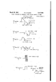
- Figs. 1a to 1 are diagrams explanatory of the wave forms present at corresponding points in the embodiment shown in Fig. 1.
- Figs. 2a, 2b and. 20 represent the mark and space signals for different conditions of tuning.
- the radiated wave in the case of telegraph transmission consists of a mark ing frequency and a spacing frequency.
- any tuning indicator or automatic frequency control device must respond equally to either condition.
- This invention provides apparatus having the necessary equal change output at the mark and space frequency, regardless of the amount of frequency drift or out-of-tune condition.
- the discriminator and rectifier combination has an over-all characteristic in which their two points of crossover with the zero voltage axis and output potentials vary by the same amount in polarity for a given change in tuning of the receiving apparatus.
- the received telegraph signals are appl ed across terminals I, these signals being received from any well known source of frequency shifted carrier waves such as a freqency shift telegraph transmitter.
- the carrier wave has a mean frequency of F0 itmay-be shifted in one direction to a frequency Fm to represent a mark signal, and in the opposite direction to a frequency of F5 to represent a space signal.
- This carrier wave may be received by any well-known radio receiver and the output of this receiver fed to terminals I.
- This balanced differential frequency discriminator comprises dual diode tube 5, coupling condenser '6, tuning condenser I, by-pass condensers 8 and 9, and equal load resistances I0 and Il connected in ba anced relationship to secondary I2 of transformer 3.
- a potentiometer I2 is connected across the output of the discriminator network 4. It is the purpose of dual diode tube I3 which is connected to potentiometer I2, to separate the positive and negative portions above the mean frequency F0 of the discriminator characteristic shown in Fig. 1a. This is necessary because a change in the mean transmitted frequency F0 or in the tuned condition of the receiver supplying energy to terminals I will cause the original mark and space frequencies to be represented by respective voltages of different magnitudes. After these positive and negative portions are separated by tube I3 and its associated circuit, they are later combined thereby creating a new characteristic which exhibits exactly the same mark and space voltage for any condition of receiver tuning. The separated negative portion appears across resistor I4 while the separated positive portion appears across resistor l5. These separated portions are shown in Figs. 1b and respectively.
- the output voltage of the discriminator network 4 is also fed to the tubes I6 and H which comprise a limiting tone keyer.
- the source of audio frequency oscil'ations I8 represents the tone to be keyed.
- the output characteristic of this keyer is such that an increase in the keying wave causes a linear increase in the keyed tone output until a certain amplitude is reached beyond which an increase of the amplitude of the keying waves causes no appreciable increase in the keyed tone output. It is seen that this amplitude limiting has the effect of removing variations of signal strength, which may be due to noise components affecting the peaks thereof.
- the tone keyer output is shown in the full line wave of Fig. 1d.
- the dotted positions of these waves represent the variable amplitude noise variations that might be present if not one limiter were used.
- the keyed tone appears across the potentiometer 23 and consists of an oscillator frequency keyed on and off in accordance with the mark and space signals.
- the potentiometer 23 allows the desired level of keyed output to be applied to the amplifier 24.
- twin triode amplifier 24 is used to amplify the keyed tone voltage appearing across potentiometer 23 and deliver it to the 500 ohm keyer output terminals 25.
- the other triode section of amplifier 24 amplifies the keyed tone voltage and feeds it through transformer 26 to the push-pull diode rectifier 21.
- the tone keyer is in the off condition, there is no output across the rectifier load resistance 28.
- the keyer is in the on condition, a voltage appears across resistance 28 and has a polarity as indicated in Fig. 1c.
- Fig. 1e shows the shape of the resultant positive voltage wave which is made equal in value by means of potentiometer arm I la, to the positive voltage across resistor I5.
- the effect of this action is to shift the negative portion of the discriminator characteristic shown in Fig. 1b in a positive direction, thereby producing the characteristic shown in Fig. 11.
- This characteristic exhibits itself at the tuning meter 3
- the detuning from the mean frequency F0 of the received signals at terminal I may be read directly from the meter scale.
- the current resulting from the intune Ea should cause one-half scale deflection of meter pointer 33, and this position should be calibrated as the zero frequency position.
- the pointer 33 will then indicate the amount and direction of the detuning of the received signals.
- the potentiometer I2 is termed the deviationcontrol and is adjusted to produce the voltage E (Fig. if) for any deviation within the range of. the equipment. This adjustment will change simultaneously the slope of each portion of the saw-tooth characteristic shown in Fig. 1f. Adjustment of potentiometer l4 compensates for numerous irregularities and enables balance of the mark and space voltages shown in Fig. 1 and appearing at meter 3
- a telegraph system for receiving a carrier frequency Fm representing a telegraph mark signal and a carrier frequency F5 representing a telegraph space signal and includin a receiver for said frequencies normally tuned to produce a predetermined base potential representing a mean frequency between Fm and F5, a balanced differential discriminator for producing mark and space voltages in response to said frequencies, rectifier means connected to said discriminator to produce positive and negative D.
- a telegraph system for receiving frequency shift telegraph mark and space signals, means to convert said signals into corresponding positive and negative D. C. voltages, means to key a tone source by said signals, means to rectify a portion of said keyed tone signals, a tuning control indicator, and means to control said indicator jointly by said voltages and by the rectified portion of said keyed tone.
- a telegraph system in which said means for keying saidtone source includes a rectifier for producing a positive D. C. potential only when a space signal is being received, and means are provided for combining said D. C. positive potential with said negative D. C. voltage.
- a balanced discriminator and rectifier for producing respective positive and negative D. C. voltages corresponding to said signals, a source of sustained tone, means to key said source on and off under control of the output of said discriminator.
- a telegraph system in which means are provided for limiting the amplitude of the keyed tone signals.
- a wave signalling frequency shift system including a balanced differential frequency discriminator which has a frequency versus potential characteristic having positive and negative portions symmetrical with respect to a predetermined mean frequency, a positive and negative wave separating circuit, a limiting tone keyer electronic circuit connected to the output of said discriminator, a push-pull diode rectifier cooperating with said keyer, and connected to the output of said wave separating circuit whereby the positive output voltage of said rectifier is in series with the said negative output, a grid-controlled linear amplifier having the above-mentioned series positive output voltage and negative output voltage impressed upon said grid, and tuning indicator means in the output circuit of said amplifier whereby the voltage applied to said amplifier is equal to the positive voltage output of said separate circuit.
- tuning indicator means comprises a current meter calibrated to indicate the frequency deviation from said mean frequency.
- a system for receiving a frequencyshifted carrier wave including a balanced differential discriminator, a positive and negative signal wave separating circuit connected to the output of said discriminator, a tone keyer connected to the output of said discriminator and adapted to key an oscillator frequency on and off in accordance with mark and space carrier waves, means to limit the amplitude of the keyed tones, signal amplifying means for amplifying the output of said keyer, electronic amplifier means connected to the positive output of said separating circuit, signal rectifier means connected to the negative output of said separating circuit and to said amplifier means whereby when a de-- tuning in said frequency-shifted carrier wave occurs, the resultant voltages representing respectively the mark and space signals preserve their original ratio and are of the same relative polarity.
- a telegraph system for receiving a carrier frequency Fm representing a telegraph mark signal, and a carrier frequency F5 representing a telegraph space signal, and including a receiver for said carriers normally tuned to produce a predetermined base potential representing the mean frequency of said two frequencies, a balanced differential discriminator circuit cooperating with a limiting tone keyer circuit and rectifier circuit, a positive signal and negative signal separating circuit cooperating with the abovementioned circuits, amplifier means connected Y to a tuning indicating meter and the output of said rectifier circuit, whereby the said negative signal separated from the said positive signal by said separating circuit is shifted in a positive direction and combined with said positive signal, thereby producing a wave having a saw-tooth section including a pair of linear sloped portions symmetrically displaced on opposite sides of said mean frequency.
Description
Mgrgh :18, 1947.
.R: s. CHAPIIN TUNING INDICATOR FOR FREQUENCY SHIFT CARRIER TELEGRAPH SYSTEMS s Shets-Sheet 1 Filed Jan. 5, 1946 & 3% E w P m 5 A. 0 0 MB TUNING INDICATOR FOR FREQUENCY SHIFT CARRIER TELEGRAPH'SYSTEMS Filed Jan. 5, 1946 s She ets-Sheet 2 w/ms SHAPE r97 Jul.
. rm VA, F5
I Fl? l F5 Wnws syn/=5 197 new:- SHAPE ,47-
'March 18, 1947.v
TUNING INDICATOR FOR FREQUENCY SHIFT CARRIER TELEGRAPH SYSTEMS IN TUNE -R. s CHAPIN Filed Jan. 5, 1946 3 Sheets-Sheet 3 INVENTOR.
A E N040 5 CHAP/N MM M M A7 TOP/VI/ Patented Mar. 18, 1947 TUNING INDICATOR FOR FREQUENCY SHIFT CARRIER TELEGRAPH TEMS SYS-
Reynold S. Chapin, Flushing, N. Y., assignor to Press Wireless, Inc., New York,N. Y., a-corporation of Delaware Application January 5, 1946, Serial No. 639,262
This invention relates to wave signalling systems and more particularly to improvements in the signalling systems of the frequency shift cate- A principal object of this invention is to provide an improved tuning indicator for use in controlling the in-tune condition of frequency shift telegraph apparatus.
A feature of th s invention relates to a discriminator and detector combination having the components so correlated and connected as to provide a characteristic having a plurality of crossover points with the zero potential axis.
Another feature relates to a differential discriminator and electron tube network for use with a frequency shifted carrier wherein any out-oftune or undesired frequency shift condition in the system results in potential changes of substantially the same magnitude and sign at both ends of the shift range,
A further feature relates to a discriminator and electron tube network for providing a sawtooth over-all relation between input frequency and output potential.
A still further feature relates to the limiting tone .keyer network whereby the adverse effects of bias variations caused by detuning of the incom ng signals and those caused by noise are substantially reduced.
A still further feature relates to the novel organization, arrangement and relative interconnection of parts which cooperate to provide an improved tuning control circuit for carrier frequency shift receiver systems.
Other features and advantages not particularly enumerated will be apparent after a consideration of the following detailed descriptions and the ap pended claims.
In the drawing which represents one preferred embodiment,
Fig. 1 shows in schemat c form, a frequency shift control and tuning indicator arrangement embodying the inventive features.
Figs. 1a to 1; are diagrams explanatory of the wave forms present at corresponding points in the embodiment shown in Fig. 1.
. Figs. 2a, 2b and. 20 represent the mark and space signals for different conditions of tuning.
When signalling is effected by frequency shifting of a radio carrier, the radiated wave in the case of telegraph transmission consists of a mark ing frequency and a spacing frequency. When such systems are provided with automatic fre quency control or tuning indicator to keep the apparatus in the in-tune condition, separate control channels are required for the two condi.
Claims. (Cl. 178- 66) tions corresponding respectively to mark and space. This has been necessary because of the frequency versus voltage characteristics of the usual discrim nators. The conventional discriminators have only a single crossover with the zero output axis, regardless of whether the system is in tune or out of tune, and this crossover point corresponds to the mean frequency of the limits between which the carrier is shifted for mark and space. When the frequency of the carrier drifts, it is manifested by a change in detected. output. With respect to the reference potential axis the detected output will increase during one of the keying signals and decrease during the other keying signal for a condition of mistuning. Since the transmitted wave may rest on either the mark or space condition for indefinite t me intervals, any tuning indicator or automatic frequency control device must respond equally to either condition. This invention provides apparatus having the necessary equal change output at the mark and space frequency, regardless of the amount of frequency drift or out-of-tune condition. The discriminator and rectifier combination has an over-all characteristic in which their two points of crossover with the zero voltage axis and output potentials vary by the same amount in polarity for a given change in tuning of the receiving apparatus.
I have disclosed in my prior application Serial No. 615,838, filed September 12, 1945, a frequency discriminator and detector arrangement having the necessary equal change of output at the mark and space frequenc es, My prior application requires a special form of ele :tronic or electromagnetic switch for controlling the required tuning indications. The present invention is in the nature of an improvement on and simplification of the system of my prior application. In the present invention no electronic or electromagnetic switches are required and instead of using an electron c limiter to produce a voltage which eventually causes a shift of the spaze signal, a rectified tone keyed-signal is used to produce the same result. In practice, a tone keyer is usually incorporated in the terminal equipment and may also be used to provide a source of D. C. voltage which may be utilized in shifting one portion of the discriminator characteristic.
Referring more particularly to Fig. 1, the received telegraph signals are appl ed across terminals I, these signals being received from any well known source of frequency shifted carrier waves such as a freqency shift telegraph transmitter. If the carrier wave has a mean frequency of F0 itmay-be shifted in one direction to a frequency Fm to represent a mark signal, and in the opposite direction to a frequency of F5 to represent a space signal. This carrier wave may be received by any well-known radio receiver and the output of this receiver fed to terminals I. For a detailed description of a typ cal carrier frequency shifting arrangement, reference may be had to application Serial No. 498,278, filed August 12, 1943.
Energy is fed from terminals I through audio transformer 3 into any well-known balanced frequency discriminator network 4. The frequency versus output voltage characteristic of this discriminator is shown in Fig. 1a. Fmindicates a mark voltage at the discriminator output, F the mean frequency voltage, and F the space voltage. This characteristic shows a substantially linear change in output voltage with frequency over the frequency range between the positive and negative peaks. This balanced differential frequency discriminator comprises dual diode tube 5, coupling condenser '6, tuning condenser I, by-pass condensers 8 and 9, and equal load resistances I0 and Il connected in ba anced relationship to secondary I2 of transformer 3.
In order to determine when the input to terminals I is in proper tune with respect to the mean frequency of the shifted carrier wave, a potentiometer I2 is connected across the output of the discriminator network 4. It is the purpose of dual diode tube I3 which is connected to potentiometer I2, to separate the positive and negative portions above the mean frequency F0 of the discriminator characteristic shown in Fig. 1a. This is necessary because a change in the mean transmitted frequency F0 or in the tuned condition of the receiver supplying energy to terminals I will cause the original mark and space frequencies to be represented by respective voltages of different magnitudes. After these positive and negative portions are separated by tube I3 and its associated circuit, they are later combined thereby creating a new characteristic which exhibits exactly the same mark and space voltage for any condition of receiver tuning. The separated negative portion appears across resistor I4 while the separated positive portion appears across resistor l5. These separated portions are shown in Figs. 1b and respectively.
The output voltage of the discriminator network 4 is also fed to the tubes I6 and H which comprise a limiting tone keyer. The source of audio frequency oscil'ations I8 represents the tone to be keyed. The output characteristic of this keyer is such that an increase in the keying wave causes a linear increase in the keyed tone output until a certain amplitude is reached beyond which an increase of the amplitude of the keying waves causes no appreciable increase in the keyed tone output. It is seen that this amplitude limiting has the effect of removing variations of signal strength, which may be due to noise components affecting the peaks thereof.
As the grids I9 and I9ct of dual tubes I6 and I1 become more positive, more current flows through the cathode resistors 20 and 2I. This is equivalent to having a high negative bias on the grids 22 and results in a downward modulation of the applied signals. For high positive bias on grids I9 cut-off occurs and a space is left between signals. Conversely as the grids I9 become more negative, less current flows through cathode resistors 29 and 2| and the effective bias on grids 22 increases. This results in an upward modulation of the applied signals for higher negative bias on grids I9. At a certain value the same value.
4 of negative bias, the tubes associated with grids I9 cut-01f, thereby limiting the tone output to a fixed value which will not rise above the cut-01f point of the tubes. This provides a tone output amplitude limiter.
The tone keyer output is shown in the full line wave of Fig. 1d. The dotted positions of these waves represent the variable amplitude noise variations that might be present if not one limiter were used. The keyed tone appears across the potentiometer 23 and consists of an oscillator frequency keyed on and off in accordance with the mark and space signals. The potentiometer 23 allows the desired level of keyed output to be applied to the amplifier 24.
One section of twin triode amplifier 24 is used to amplify the keyed tone voltage appearing across potentiometer 23 and deliver it to the 500 ohm keyer output terminals 25. The other triode section of amplifier 24 amplifies the keyed tone voltage and feeds it through transformer 26 to the push-pull diode rectifier 21. When the tone keyer is in the off condition, there is no output across the rectifier load resistance 28. When the keyer is in the on condition, a voltage appears across resistance 28 and has a polarity as indicated in Fig. 1c.
The positive voltage appearing across resistor 28 is in series with the negative voltage appearing across resistor I4. The resultant of these voltages is conveyed to the grid 29 of linear amplifier 36. Fig. 1e shows the shape of the resultant positive voltage wave which is made equal in value by means of potentiometer arm I la, to the positive voltage across resistor I5. The effect of this action is to shift the negative portion of the discriminator characteristic shown in Fig. 1b in a positive direction, thereby producing the characteristic shown in Fig. 11. This characteristic exhibits itself at the tuning meter 3| connected in the output circuit of linear amplifier 38. It will thus be seen that grid 32 is excited with a positive voltage which is independent of the tone keyer, while grid 29 is excited with an equal positive voltage which is the resultant of the voltages at point B and the rectified tonekeyed voltage appearing across resistor 28.
From Fig. If it is seen that Fm and F5 are of If the input to terminal I should drift, the resultant voltage of Fm and Fe will remain the same since these two signals equally increase or decrease with respect to the in-tune voltage E1; and their direction of change is dependent upon the direction of the input drift. The voltages applied to the linear amplifier 30 are such that the resultant current passed through the meter 3| is proportional to the voltages applied to grids 29 and 32. Since both mark and space signals Fm and F5 are of the same voltage, the same current will flow through meter 3| for the mark signal and space signal.
By calibration of meter 3|, the detuning from the mean frequency F0 of the received signals at terminal I may be read directly from the meter scale. The current resulting from the intune Ea should cause one-half scale deflection of meter pointer 33, and this position should be calibrated as the zero frequency position. The pointer 33 will then indicate the amount and direction of the detuning of the received signals.
The potentiometer I2 is termed the deviationcontrol and is adjusted to produce the voltage E (Fig. if) for any deviation within the range of. the equipment. This adjustment will change simultaneously the slope of each portion of the saw-tooth characteristic shown in Fig. 1f. Adjustment of potentiometer l4 compensates for numerous irregularities and enables balance of the mark and space voltages shown in Fig. 1 and appearing at meter 3|.
While there has been here described a specific embodiment, various changes and modifications may be made therein without departing from the spirit and scope of the invention.
What is claimed is:
1. In a telegraph system for receiving a carrier frequency Fm representing a telegraph mark signal and a carrier frequency F5 representing a telegraph space signal and includin a receiver for said frequencies normally tuned to produce a predetermined base potential representing a mean frequency between Fm and F5, a balanced differential discriminator for producing mark and space voltages in response to said frequencies, rectifier means connected to said discriminator to produce positive and negative D. C. voltages cor p n in to said signals, a source of sustained tone frequency, means to key said source on and off in synchronism with the received signals, means to rectify and combine a portion of the keyed output of said source with one of said D. C. voltages to produce a resultant, and a tuning control indicator which is energized by the other of said D. C. voltages and by said resultant.
2. In a telegraph system for receiving frequency shift telegraph mark and space signals, means to convert said signals into corresponding positive and negative D. C. voltages, means to key a tone source by said signals, means to rectify a portion of said keyed tone signals, a tuning control indicator, and means to control said indicator jointly by said voltages and by the rectified portion of said keyed tone.
3. A telegraph system according to claim 2 in which said means for keying saidtone source includes a rectifier for producing a positive D. C. potential only when a space signal is being received, and means are provided for combining said D. C. positive potential with said negative D. C. voltage.
4. In a telegraph system, means to receive two frequencies representing respectively mark and space, a balanced discriminator and rectifier for producing respective positive and negative D. C. voltages corresponding to said signals, a source of sustained tone, means to key said source on and off under control of the output of said discriminator. means to rectify the keyed tone signal to produce a positive D. C. voltage, a pair of grid-controll d amplifier paths, means to combine said rectified tone signal withthe negative D. C. voltage from said discriminator rectifier to produce a resultant, means to apply said resultant to one of said amplifiers, means to apply the positive rectified discriminator voltage to the other of said paths, and a common output circuit for the plates of both said amplifier paths, said output circuit including a tuning indicator device.
5. A telegraph system according to claim 4 in which means are provided for limiting the amplitude of the keyed tone signals.
6. A wave signalling frequency shift system including a balanced differential frequency discriminator which has a frequency versus potential characteristic having positive and negative portions symmetrical with respect to a predetermined mean frequency, a positive and negative wave separating circuit, a limiting tone keyer electronic circuit connected to the output of said discriminator, a push-pull diode rectifier cooperating with said keyer, and connected to the output of said wave separating circuit whereby the positive output voltage of said rectifier is in series with the said negative output, a grid-controlled linear amplifier having the above-mentioned series positive output voltage and negative output voltage impressed upon said grid, and tuning indicator means in the output circuit of said amplifier whereby the voltage applied to said amplifier is equal to the positive voltage output of said separate circuit.
7. A claim in accordance with claim 6, wherein said tuning indicator means comprises a current meter calibrated to indicate the frequency deviation from said mean frequency.
8. In a system for receiving a frequencyshifted carrier wave and including a balanced differential discriminator, a positive and negative signal wave separating circuit connected to the output of said discriminator, a tone keyer connected to the output of said discriminator and adapted to key an oscillator frequency on and off in accordance with mark and space carrier waves, means to limit the amplitude of the keyed tones, signal amplifying means for amplifying the output of said keyer, electronic amplifier means connected to the positive output of said separating circuit, signal rectifier means connected to the negative output of said separating circuit and to said amplifier means whereby when a de-- tuning in said frequency-shifted carrier wave occurs, the resultant voltages representing respectively the mark and space signals preserve their original ratio and are of the same relative polarity.
9. In a telegraph system for receiving a carrier frequency Fm representing a telegraph mark signal, and a carrier frequency F5 representing a telegraph space signal, and including a receiver for said carriers normally tuned to produce a predetermined base potential representing the mean frequency of said two frequencies, a balanced differential discriminator circuit cooperating with a limiting tone keyer circuit and rectifier circuit, a positive signal and negative signal separating circuit cooperating with the abovementioned circuits, amplifier means connected Y to a tuning indicating meter and the output of said rectifier circuit, whereby the said negative signal separated from the said positive signal by said separating circuit is shifted in a positive direction and combined with said positive signal, thereby producing a wave having a saw-tooth section including a pair of linear sloped portions symmetrically displaced on opposite sides of said mean frequency.
10. A claim in accordance with claim 9, wherein when said system is in the in-tune condition, the current drawn by said meter from said amplifier means causes the pointer of said meter to be deflected half the scale.
' REYNOLD S. CHAPIN.
REFERENCES CITED The following references are of record in the file of this patent:
UNITED STATES PATENTS Number Name Date 2,293,831 Koch Aug. 25, 1942 2,395,725 Crosby Feb. 26, 1946 2,309,481 Summerhayes Jan. 26, 1943
Priority Applications (1)
| Application Number | Priority Date | Filing Date | Title |
|---|---|---|---|
| US639262A US2417543A (en) | 1946-01-05 | 1946-01-05 | Tuning indicator for frequency shift carrier telegraph systems |
Applications Claiming Priority (1)
| Application Number | Priority Date | Filing Date | Title |
|---|---|---|---|
| US639262A US2417543A (en) | 1946-01-05 | 1946-01-05 | Tuning indicator for frequency shift carrier telegraph systems |
Publications (1)
| Publication Number | Publication Date |
|---|---|
| US2417543A true US2417543A (en) | 1947-03-18 |
Family
ID=24563381
Family Applications (1)
| Application Number | Title | Priority Date | Filing Date |
|---|---|---|---|
| US639262A Expired - Lifetime US2417543A (en) | 1946-01-05 | 1946-01-05 | Tuning indicator for frequency shift carrier telegraph systems |
Country Status (1)
| Country | Link |
|---|---|
| US (1) | US2417543A (en) |
Cited By (6)
| Publication number | Priority date | Publication date | Assignee | Title |
|---|---|---|---|---|
| US2463402A (en) * | 1946-07-30 | 1949-03-01 | Collins Radio Co | Frequency shift carrier system |
| US2510531A (en) * | 1947-10-31 | 1950-06-06 | Rca Corp | Transmitter monitor |
| US2571650A (en) * | 1947-11-07 | 1951-10-16 | Rca Corp | Peak-reading tuning indicator |
| US2586880A (en) * | 1949-11-12 | 1952-02-26 | Standard Telephones Cables Ltd | Resonance indicator |
| US2606961A (en) * | 1942-12-30 | 1952-08-12 | Bell Telephone Labor Inc | Carrier telegraph repeater |
| US2915741A (en) * | 1955-11-16 | 1959-12-01 | Tele Dynamics Inc | Automatic compensation in a telemetric system |
Citations (3)
| Publication number | Priority date | Publication date | Assignee | Title |
|---|---|---|---|---|
| US2293831A (en) * | 1939-11-30 | 1942-08-25 | Rca Corp | Signal detecting system |
| US2309481A (en) * | 1941-03-01 | 1943-01-26 | Gen Electric | Frequency monitoring system |
| US2395725A (en) * | 1943-03-27 | 1946-02-26 | Rca Corp | Frequency modulation receiver tuning indicator |
-
1946
- 1946-01-05 US US639262A patent/US2417543A/en not_active Expired - Lifetime
Patent Citations (3)
| Publication number | Priority date | Publication date | Assignee | Title |
|---|---|---|---|---|
| US2293831A (en) * | 1939-11-30 | 1942-08-25 | Rca Corp | Signal detecting system |
| US2309481A (en) * | 1941-03-01 | 1943-01-26 | Gen Electric | Frequency monitoring system |
| US2395725A (en) * | 1943-03-27 | 1946-02-26 | Rca Corp | Frequency modulation receiver tuning indicator |
Cited By (6)
| Publication number | Priority date | Publication date | Assignee | Title |
|---|---|---|---|---|
| US2606961A (en) * | 1942-12-30 | 1952-08-12 | Bell Telephone Labor Inc | Carrier telegraph repeater |
| US2463402A (en) * | 1946-07-30 | 1949-03-01 | Collins Radio Co | Frequency shift carrier system |
| US2510531A (en) * | 1947-10-31 | 1950-06-06 | Rca Corp | Transmitter monitor |
| US2571650A (en) * | 1947-11-07 | 1951-10-16 | Rca Corp | Peak-reading tuning indicator |
| US2586880A (en) * | 1949-11-12 | 1952-02-26 | Standard Telephones Cables Ltd | Resonance indicator |
| US2915741A (en) * | 1955-11-16 | 1959-12-01 | Tele Dynamics Inc | Automatic compensation in a telemetric system |
Similar Documents
| Publication | Publication Date | Title |
|---|---|---|
| US2211750A (en) | Wireless telegraph system | |
| US2423229A (en) | Automatic tuning control and indication for frequency shift systems | |
| US2371397A (en) | Frequency modulation receiver tuning aid | |
| US2417543A (en) | Tuning indicator for frequency shift carrier telegraph systems | |
| US2194516A (en) | Visual signal carrier indicator | |
| US1861462A (en) | Radio station | |
| US2477963A (en) | Frequency discriminator for carrier shift signaling systems and the like | |
| US2100394A (en) | Reception of frequency modulated waves and circuits therefor | |
| US2115813A (en) | Method and apparatus for controlling radio receivers | |
| US2423225A (en) | Frequency shift telegraph receiver tunning indicator | |
| US2689881A (en) | Circuit means for adjusting frequency keyed telegraph receivers | |
| US2496818A (en) | Angle modulation detector | |
| US2507735A (en) | Automatic tuning control apparatus | |
| US2243414A (en) | Frequency modulating receiver | |
| US2302951A (en) | Diversity receiving system | |
| US2446077A (en) | Frequency-shift telegraph system | |
| US2286410A (en) | Frequency modulation receiver tuning indicator | |
| US2502154A (en) | Carrier shift receiving system | |
| US2409845A (en) | Calibrating device | |
| US2177713A (en) | Frequency-selective network | |
| US2477962A (en) | Frequency shift tuning indicator system | |
| US2369585A (en) | Frequency modulation receiver | |
| US2123221A (en) | Radio circuit for channel reception | |
| US2118161A (en) | Receiving system for frequency modulated waves | |
| US2066940A (en) | Radio receiving system |