US2407170A - Control mechanism - Google Patents
Control mechanism Download PDFInfo
- Publication number
- US2407170A US2407170A US466962A US46696242A US2407170A US 2407170 A US2407170 A US 2407170A US 466962 A US466962 A US 466962A US 46696242 A US46696242 A US 46696242A US 2407170 A US2407170 A US 2407170A
- Authority
- US
- United States
- Prior art keywords
- valve
- movement
- lever
- control device
- diaphragm
- Prior art date
- Legal status (The legal status is an assumption and is not a legal conclusion. Google has not performed a legal analysis and makes no representation as to the accuracy of the status listed.)
- Expired - Lifetime
Links
- 230000007246 mechanism Effects 0.000 title description 18
- 239000007789 gas Substances 0.000 description 20
- 238000004804 winding Methods 0.000 description 11
- 238000002485 combustion reaction Methods 0.000 description 7
- 241000894007 species Species 0.000 description 6
- 239000004020 conductor Substances 0.000 description 5
- 239000000446 fuel Substances 0.000 description 5
- 230000009471 action Effects 0.000 description 2
- 238000013459 approach Methods 0.000 description 2
- 238000006073 displacement reaction Methods 0.000 description 2
- 102100023170 Nuclear receptor subfamily 1 group D member 1 Human genes 0.000 description 1
- 150000001768 cations Chemical class 0.000 description 1
- 230000008859 change Effects 0.000 description 1
- 244000145845 chattering Species 0.000 description 1
- 210000005069 ears Anatomy 0.000 description 1
- 230000000694 effects Effects 0.000 description 1
- 230000002452 interceptive effect Effects 0.000 description 1
- 239000000463 material Substances 0.000 description 1
- 230000004048 modification Effects 0.000 description 1
- 238000012986 modification Methods 0.000 description 1
- 238000005192 partition Methods 0.000 description 1
- 230000035699 permeability Effects 0.000 description 1
- 239000002912 waste gas Substances 0.000 description 1
Images

Classifications
-
- F—MECHANICAL ENGINEERING; LIGHTING; HEATING; WEAPONS; BLASTING
- F23—COMBUSTION APPARATUS; COMBUSTION PROCESSES
- F23N—REGULATING OR CONTROLLING COMBUSTION
- F23N5/00—Systems for controlling combustion
- F23N5/02—Systems for controlling combustion using devices responsive to thermal changes or to thermal expansion of a medium
- F23N5/10—Systems for controlling combustion using devices responsive to thermal changes or to thermal expansion of a medium using thermocouples
-
- F—MECHANICAL ENGINEERING; LIGHTING; HEATING; WEAPONS; BLASTING
- F23—COMBUSTION APPARATUS; COMBUSTION PROCESSES
- F23Q—IGNITION; EXTINGUISHING-DEVICES
- F23Q9/00—Pilot flame igniters
- F23Q9/08—Pilot flame igniters with interlock with main fuel supply
- F23Q9/12—Pilot flame igniters with interlock with main fuel supply to permit the supply to the main burner in dependence upon existence of pilot flame
Definitions
- the present invention is concerned Vwith a control mechanism and more particularly with one in which a control deviceisstopped temporarily at an intermediate position in moving between two extreme controlling positions.
- Anrobject of the present invention is to provide an arrangement including a control device movable between rst and second positions in 16 Claims.
- a still further object of the present invention is to provide such an arrangement in which the electromagnetic means is effective to move the impeding means from an impeding position to one inv which the control device is free to move to its second position.
- a still further object of the present invention is t provide an' arrangement of the type set forth in which the electromagnetic means is' energized an appreciable period of time subsequent to movement of the control device to the intermediate position.
- 4A further object of the present invention-is to providesuch a control arrangement in which the impeding means is effectiveto interfere-with the movement of the fcontrol device only when it is moved in onedirection.
- a still further object of the invention is to provide such an arrangement in which the control device is .a valve which is interrupted in its movement from closed to open position.
- ArurtherA object of the present ⁇ invention is to provide such a controllingarrangement inwhich the controlling device is al diaphragm valve and the impeding means is a stop in the path of the valve.
- a further object of the invention is to provide such an Varrangement in which the stop is electromagnetically positioned and in which means are provided for adjusting the intermediate position without interfering with the spacing between the armature and the electromagnet.
- a still further object of the invention is to provide a controlling arrangement of the type set forth in theprevious objects in which the control deviceis" ⁇ employed t0 control the operation of a burner and in which ⁇ theimpeding means is f moved from its impeding position under the control of means responsive to the establishment of combustion.
- a Still further object of the, present invention is toprovide a controlling arrangement employ- Ying an electromagnet and an armature in which it is possible to adjust theposition of the electromagnet and the armaturefsimultaneously to vary the action of the electromagnetand armature on a controlling device without affecting the relative Vpositions of the electromagnet ⁇ and armature.
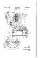
- Figure l is aschematic view of a burner control system employing my improved control mechanism, the burner control mechanism being sho-wn in vertical section;
- Figure 3 is a vertical sectional view ci a modified form oi my control mechanism;
- Figuree is a horizontal' sectional view ofl th modification of Figure'B;
- Figure 5 is a detail View of a ⁇ portion of the of the control device of Figures 3 and 4.
- my Vcorrtrol device l is shown as controlling the flow of fuel to a main burner lliwhich is supplied with gas by a pipe II Whichlconnects with the outlet ofmy control valve I 2 ⁇ .
- the inlet of the valve connects with a pipe I3 leadingiroin any suitable source'o'f gas (not shown) ⁇
- a pilot burner I4 Located-adjacent' to the ymain burner "0 is a pilot burner I4.
- the pilot burner I Ai connected 'bypipes I5 and I6 with the supply pipe I3 and 'is normally constantly burning.
- fmy improved'control mechanism I2 comprises a housing fhavinga lower housing-i section z and an' 'upper housing section 2I.
- a diaphragm "22 is secured between the two sections andv the upper and lower housing sections and'diaphragm'ZZ are clamped together by any suitableclamping means (not shown)
- the lower ⁇ section 20 constitutes the valve casing and has theusual inlet connection 24 to whichV pipe VI3 is connected and an outlet connection towhich pipe "II is connected.
- ⁇ Extending between the inlet and outlet connections!!! and 25 is a partition wall ⁇ 26" "having an opening therethrough Ito provide a valve seat 21.
- the centralportion ⁇ of the diaphragm 22 seats on this valve seat 23.
- a backing plate 28 and a throttlingskirt 29 are clamped against this central portion of ⁇ the diaphragm by al bolt 30 andnut 3
- the backing plategZS serves to re-enforce the portion of the diaphragm whichvacts as thevalve disk.
- ⁇ The throttling skirt serves to graduate the now and make possible the establishment of an intermediate condition of flow.
- acts together with diaphragm 22 to enclose a pressure chamber 32.
- the pressure within this chamber 32 aiects the pressure differential acting on diaphragm. zzand hence serves tov control the movement OPdiaphra'gm ⁇ 22 between its open and closed positions.
- pilot valve 35 The gas pressure within the chamber 32 is con-l trolled by means of a pilot valve generally indicated by the reference numeral 35.
- Thispilot valve and its operating mechanism is illustrated in greater detail in th'e copending application of Daniel G. Taylor, Serial No.v 390,553, led April 26, 1941 and issued on MayA 16, 1944, as Patent No. 2,349,209. Reference is made to that application for a detailed understanding of the pilot valve. cation, this pilot valve comprises. a housing 36 having a pair ofvalve chambers 3'1 and 38; The valve housing 36 isprovided with'cpenings 39, 40 and. 4
- the passage 40 connects with a pipe 43 connected to thel pressure chamber 32- within housing section 2
- the inner end of opening'4'9 is connected to a chamber ⁇ 44 which is adapted to be placed into communication' with either chambe'r 31 or chamber 38.
- which connects with chamber 38 is connected with a pipe 45 which leads to bleed burner 46 for burning the waste gas.
- the chamber 38 constitutes the outlet chamber of the valve mechanism.y
- Each of the chambers 31 andV 38 has an inturned portion at its outer end to. form a valve seat'.
- a ball Valve 48 isfloca'ted within chamber 31 and a ball valve 49- in chamber 38.
- are located within chambers 31 and 38, respectively. and serve to bias the ball valves outwardly against their seats'.
- valve 4 8y When, on the other hand, valve 4 8y is against its v seat and valve 49 is away from its seat, communication is established betweeny openingV 40 and opening4
- the chamber 44 is sealed from the atmosphere by a diaphragm.' 53 which is suitably clamped to the pilot valve assembly by any suitable means such as a frame 54 and screws 55.
- a ⁇ rocker 51l is til-tably secured to the frame 54 at 58.
- the rocker carries adjustable screws 59 and 69 whose stems extend inwardly towards the pilot valve assembly and engage the diaphragm 53 through openings in the frame 54 for actuating the ballva-lves 48 and 49.
- the rocker 51 and the actuating screws 59- and 68 are so arranged that when the rocker ⁇ assumes th'e mid-position both of the valves 48 and 49 are closed so that the pressure withinA the pressure chamber 32 remains at a constant Value.
- the rocker 51 is adapted t0 be actuated automatically by means of an electromagnet 64.
- This electromagnei-l may be of any suitable type but is shown schematically as comprising an L shaped magnetic frame element 65. Secured to one leg of the L shaped frame member is a core post 66 around which a winding 61 is located. Pivotally secured to the lower end of the other leg of the inverted L shaped element 65 is an armature member 68 which is designed to cooperate withthel core post 66. Upon energization of the winding 61y thel armature member 68 is rotated in clockwise direction into engagement with the end of the core post 66. As is common with A. C.
- the end of the post 66 engaged by the armature 68 is provided with a shading ring 12 to shadeaportion. of the iiux and.A hence decrease chattering of th'e relay.
- the righthand end of armature 68 is' provided with an upstanding arm 69 adapted to extend into aslot 18 of an ear 1
- a room thermostat 15 isemployed to control the energization of winding 61 and-hence the operation of pilot-valve 35.
- This thermostat is of conventional formv and is shown as comprising a bimetallic element 16 to which isy secured a contactY arm 11.
- the contact arm is designed to cooperate with a iixed contact 18.
- the bimetallic element 16 is so-arranged thatl upon a drop in temperature, the contact arm 11 is moved to'- wards the right into engagement with the contact 18; Upon arise' in temperature on the other hand, the contact arm 11 is moved to the left away from contact 18.
- a step-down' transformer 89 is employed for supplying power to the electromagnet 64;
- This transformer comprises a line Voltage primary 8
- is connected to'any suitable source of power (not shown).
- a biasingr spring 96 is secured at its upper end. to the housing section 2
- the length of the pivot pin 93 is several times as great as the Width of lever 90.
- the lever 90 can thus be shifted along the pivot pin 93.
- a leaf spring 98 is interposed between one end of bracket 94 and the lever 90 and serves to bias lever 90 toward the rear (as viewed in Figure 1). This biasing movement is resisted by a cam 99 carried on a shaft
- the shaft extends through the Wall of housing section 2
- 00 has secured thereto a knurled knob I 0I. There is a close frictional fit between the shaft
- the lever 86 which as previously explained,.is mounted for pivotal movement in a horizontal plane, carries an armature
- This armature is adapted to cooperate with an electromagnet
- 05 are both of very high permeability material.
- 06 is a relatively low resistance winding and is connected by low resistance conductors
- 02 is fastened at one end to the housing section 2
- 09 upon being exposed to the ame of the main burner I0, is capable of generatin-g sufcient current to energize the elec- -tromagnet
- the ball valve 48 is away from its seat so that gas may flow from pipe I3 through pipes I6 and 42, passage 39, chamber 31 to chamber 44, and
- thermo.V thermo.V
- valve is permitted to move to some intermediate position. This position is adjusted by adjusting the cam 99 through the rotation of shaft
- thermopile After a predetermined period of time sufficient for the hot junctions of the thermopile to become adequately heated, the thermopile
- 09 is no longer heated.
- thel electromotive force supplied by the thermopile to the electromagnet is suffcientlysmall that the spring
- the means for adjusting the intermediate positionl does not in any way affect the spacing between the arma- The only member which is moved as a result ofV the adjustment process-is lever 99.
- Lever 36- remains in the same position. This is: extremely important since the spacing between the armature and the electromagnet is extremely critical when a limited source'of power such as a thermopile is employed. While this spacing hasv been shown' as greatly exaggerated for purposes of illustration, actually the spacing is extremely small.
- Figures 3A to 5 differs from that o-f Figures 1 and 2 solely in the means for adjusting the intermediatepositiony of the valve.
- elements in. Figures 3. to corresponding to elements in Figures 1 and 2 are referred to by the same reference numerals.
- the details of the valve housing 29 are exactly the same as in Figures v1 and 2, and it is believed unnecessary to again describe these details.
- similarly encloses apressure chamber 32 to which. is connected av pipe 43.
- the manner of controlling the pressure within the chamber 32 is identically the same as in Figures 1 and 2.
- bracket 94 which carries a pivot pin 93.
- a lever 90 Journalled on the pin 93 is a lever 90 which carries at its left-hand end a button 89 having a plate 9
- Aspring 95 biases the lever in a counter-clockwise direction as in the species of Figures l and 2.
- 25 is secured to the upper wall of housing section 2
- 26 The left-handA end of lever
- 29 is in turn journalled to a bracket
- This armature cooperates with a core
- 34 is an electromagnetic winding
- 35 is secured to a bracket
- 39 which is connected to the lever
- 30 isprovided with any ear
- 40 determines the spacing of armature
- 34 are both secured to a carriage
- the bracket 43 is provided with a slot
- 43 is provided with an opening
- 43 is provided with an ear
- 49 are provided with aligned apertures, the aperture through ear
- 49 is a shank portion of a screw
- 52 are secured to the screw
- 50 extends through. the housing sectionv 2
- thermoelectric means responsive to A the establishment of combustion for causing said control device-to continue to move toward said second position.
- thermoelectric means responsive to the ,establishment of combustion for energizing said electromagneticA means.
- thermoelectric actuated means responsive to the establishment of combustion for causing the removal of said interruptingmeans'to permit said valve to move to full open position, said interrupting means being ineective to a impede closing movement of said ValVe.
- a diaphragm valve means for controlling the pressure .dilerential acting on said diaphragm valve to cause said diaphragm valve to move between closed and full open positions, a stop movable independently of said valve between a rst position in which it stops opening movement of ⁇ said valve at an intermediate position and a second position in which said valve is free to moveV on 4to said open position, and
- means for controlling the pressure differential acting on said diaphragm valve to cause said diaphragm l valve to move between closed and full open positions means for causing said valve to open in a plurality or steps and including a stop biased to a position in which it stops opening movement of said valve at an adjustable intermediate position to complete a rst opening step, and electromagnetic means for moving said stop to a second position in which the valve is free to move to open position to complete the second step.
- a diaphragm Valve means for controlling the pressure differential acting on said diaphragm valve to cause said diaphragm valve to move between closed and full open positions, a stop normally in a position in which it stops opening movement of said valve at an intermediate position, a member interposed betermediate position, electromagnetic means for moving said stop to a second position in which the lvalve is free to move to open position, and heat responsive means operable upon movement of said valve to intermediate position for controlling the energization of said electromagnetic means.
- a diaphragm valve having a pressure chamber on one side of the valve, means for controlling the pressure within said chamber to cause said diaphragm valve to move between closed and full open positions, a stop within said pressure chamber and normally in a position in which it stops movement of said valve at a position intermediate its extreme of travel, and electromagnetic means for moving said stop independently of said valve to a second position in which the valve is free to move to its extreme position of travel.
- a control device movable between iirst and second controlling positions, a stop normally assuming a position in which it prevents 'movement of said device beyond an intermediate position, 'a lever carrying said stop and an ar'ma't'ur'e, an el'ectromagnet for co- Operating' With Sad armature 'to move Said level' and said stopV to a position in which said device may move to said second position, and means'for f adjusting the normal relationship between said stop and said control device without aiiecting the spacing oi said armature and electromagnet;
- a control device movable between frrstand second controlling positions, a stop, a first lever interposed between said stop and' control device and movable in the'direction of movement of said device, said 'first lever acting to connect said stop to 'said device so that said stop prevents movement of said device beyond an intermediate positiomone ofthe cooperating faces of sa'id stop and iirst lever being inclin'ed, means for adjusting said rst lever transversely'oi the direction of movement of said device to adjust said intermediate position, a second lever carrying said stop and an armature', and an electromagnet for cooperating with said armature to move'said second lever and said stop to a position in which said device may'move to said second position.
- a control device movable between first and second'controllin'g positions, a stop normally assuming a position in which it prevents movement orsaid device beyond an intermediate position', a lever carrying said stop and an armature, an electromagriet for cooperating with said lever to move said lever and said 'stop to a position in which said device may move to said second position, and means for simultaneously adjusting the position of said electromagnet and armature in relation to said control device so as to adjust-said intermediate position without affecting the normal spacing of said electromagnet and armature.
- a control device movable between nrst and second extreme positions
- abutment means movable in a direction normal to the movement of said control device and having a rst position in which it arrests the movement of said control device intermediate said extreme positions and a second position in which said control device is free to move on to said second extreme position
- a member interposed between said abutment means and said control device, said interposed
- a control device movable between nrst and second extreme positions, means for arresting the movement of said control device from said first position at a variable point inter'- mediate said extreme positions, said means including an abutment member and an abutment engaging member, one of said members being adjustable relative to the other to engage different portions of the other to determine the point for arresting the movement of said control device, and means for moving said abutment member to release said control device for movement to said second extreme position,
- a control device movable between first and second extreme positions, means for arresting the movement of said control device intermediate said extreme positions, said means comprising an abutment engaging member and an abutment member, said abutment member and said abutment' engaging member being relatively adjustable to engage different portions of their engaging surfaces to selectively determine the intermediate position at which movement of said control device is arrested, and means for moving said abutment member to" release said control device for continued movement to said second extreme position.
- a control device movable between first and second controlling positions, abutment means for arresting the movement of said control device intermediate said first and said second positions, means 'interposed between said abutment means and said control device and operable to selectively determine the intermediate stopping position of saidv control device, electromagnetic means for moving said abutment means to a position in which said control device is free to move on to said second controlling position, and means operable as a result of the movement of said control device to said intermediate position to energize said electromagnetic means.
- a flow control device movable between iirst, second, and thirdv controlling positions, means for arresting the movement of said control device at said second position to establish a minimum flow condition, means for selectively adjusting 'said second position relative to said first and said third positions, said last named means including a member engageable with an inclined surface of said arresting means at a point determined by the relative adjustment of said engaging parts, 'means for moving said arresting means toa position in which said control device is free to'move to said third position, and means brought into-operation as a result of the movement of said control device tosaid second position for actuating said moving means.
Landscapes
- Engineering & Computer Science (AREA)
- Chemical & Material Sciences (AREA)
- Combustion & Propulsion (AREA)
- Mechanical Engineering (AREA)
- General Engineering & Computer Science (AREA)
- Magnetically Actuated Valves (AREA)
Description
sept 3, 1946 s. K. MALEK 2,407,170
CONTROL MECHANISM I Filed Nov. 25, 1942 -2 Sheets-Sheet 1 Gttorneg Sept 3,1945 s. K, MALEK 2,407,170
CONTROL MECHANISM Filed Nov. 25, 1942 2 Sheets-Sheet 2' I Gttorneg Patented Sept. 3, 1946 CONTROL MECHANISM Sidney K. Malek, Minneapolis, Minn., assgnor to Minneapolis-Honeywell Regulator Company, Minneapolis, Minn., a corporation of Delaware f Application November 25, 194.2, Serial No. 466,962`
The present invention is concerned Vwith a control mechanism and more particularly with one in which a control deviceisstopped temporarily at an intermediate position in moving between two extreme controlling positions. l i
Anrobject of the present invention is to provide an arrangement including a control device movable between rst and second positions in 16 Claims.
which an impeding means is present for tem- `po'rarily impeding the movement of the control device from the rst position, beyond an intermediate positionrwith electromagnetic means for positioning this impeding means. y
A still further object of the present invention is to provide such an arrangement in which the electromagnetic means is effective to move the impeding means from an impeding position to one inv which the control device is free to move to its second position. 1 i
A still further object of the present invention is t provide an' arrangement of the type set forth in which the electromagnetic means is' energized an appreciable period of time subsequent to movement of the control device to the intermediate position. p
4A further object of the present invention-is to providesuch a control arrangement in which the impeding means is effectiveto interfere-with the movement of the fcontrol device only when it is moved in onedirection.` i
A still further object of the invention is to provide such an arrangement in which the control device is .a valve which is interrupted in its movement from closed to open position.
ArurtherA object of the present` invention is to provide such a controllingarrangement inwhich the controlling device is al diaphragm valve and the impeding means is a stop in the path of the valve.
A further object of the invention is to provide such an Varrangement in which the stop is electromagnetically positioned and in which means are provided for adjusting the intermediate position without interfering with the spacing between the armature and the electromagnet.
A still further object of the invention is to provide a controlling arrangement of the type set forth in theprevious objects in which the control deviceis"`employed t0 control the operation of a burner and in which `theimpeding means is f moved from its impeding position under the control of means responsive to the establishment of combustion. i
A Still further object of the, present invention -is toprovide a controlling arrangement employ- Ying an electromagnet and an armature in which it is possible to adjust theposition of the electromagnet and the armaturefsimultaneously to vary the action of the electromagnetand armature on a controlling device without affecting the relative Vpositions of the electromagnet `and armature.
Still further objects of the invention will be apparent froma `consideration of the accompanying `speciiication,A claims and drawings, of which:
Figure l is aschematic view of a burner control system employing my improved control mechanism, the burner control mechanism being sho-wn in vertical section;
` Figure 2is a horizontal sectional view of my `contro-l mechanism; f
Figure 3 is a vertical sectional view ci a modified form oi my control mechanism; Figuree is a horizontal' sectional view ofl th modification of Figure'B; and
Figure 5 is a detail View of a `portion of the of the control device of Figures 3 and 4.
`Referring tothe drawings, my Vcorrtrol device lis shown as controlling the flow of fuel to a main burner lliwhich is supplied with gas by a pipe II Whichlconnects with the outlet ofmy control valve I 2`. The inlet of the valve connects with a pipe I3 leadingiroin any suitable source'o'f gas (not shown)` Located-adjacent' to the ymain burner "0 is a pilot burner I4. The pilot burner I Aiis connected 'bypipes I5 and I6 with the supply pipe I3 and 'is normally constantly burning.
Referring to fmy improved'control mechanism I2, this? comprises a housing fhavinga lower housing-i section z and an' 'upper housing section 2I. A diaphragm "22 is secured between the two sections andv the upper and lower housing sections and'diaphragm'ZZ are clamped together by any suitableclamping means (not shown) The lower `section 20 constitutes the valve casing and has theusual inlet connection 24 to whichV pipe VI3 is connected and an outlet connection towhich pipe "II is connected. `Extending between the inlet and outlet connections!!! and 25 is a partition wall `26" "having an opening therethrough Ito provide a valve seat 21. The centralportion `of the diaphragm 22 seats on this valve seat 23. i
A backing plate 28 and a throttlingskirt 29 are clamped against this central portion of `the diaphragm by al bolt 30 andnut 3|. The backing plategZS serves to re-enforce the portion of the diaphragm whichvacts as thevalve disk. `The throttling skirt serves to graduate the now and make possible the establishment of an intermediate condition of flow.
Th'e upper housing section 2| acts together with diaphragm 22 to enclose a pressure chamber 32. The pressure within this chamber 32 aiects the pressure differential acting on diaphragm. zzand hence serves tov control the movement OPdiaphra'gm` 22 between its open and closed positions.
The gas pressure within the chamber 32 is con-l trolled by means of a pilot valve generally indicated by the reference numeral 35. Thispilot valve and its operating mechanism is illustrated in greater detail in th'e copending application of Daniel G. Taylor, Serial No.v 390,553, led April 26, 1941 and issued on MayA 16, 1944, as Patent No. 2,349,209. Reference is made to that application for a detailed understanding of the pilot valve. cation, this pilot valve comprises. a housing 36 having a pair ofvalve chambers 3'1 and 38; The valve housing 36 isprovided with'cpenings 39, 40 and. 4|. Opening 39 opens into the' chamber 31 and connects at its outer end; with a' pipe 42 joining with a pipe 6 extending to the gas supply pipe 3. The chamber 31 thus constitutes the inlet' chamber of the valve mechanism.
The passage 40 connects with a pipe 43 connected to thel pressure chamber 32- within housing section 2|. The inner end of opening'4'9 is connected to a chamber` 44 which is adapted to be placed into communication' with either chambe'r 31 or chamber 38.
Opening 4| which connects with chamber 38 is connected with a pipe 45which leads to bleed burner 46 for burning the waste gas. Thus, the chamber 38 constitutes the outlet chamber of the valve mechanism.y
Each of the chambers 31 andV 38 has an inturned portion at its outer end to. form a valve seat'. A ball Valve 48 isfloca'ted within chamber 31 and a ball valve 49- in chamber 38. Springs 50 and 5| are located within chambers 31 and 38, respectively. and serve to bias the ball valves outwardly against their seats'. When ball valve '48 is moved to openA position, communication is 'establishedbetween openingv 39 and opening 48 lleading to the pressure chamber of the valve.
When, on the other hand, valve 4 8y is against its v seat and valve 49 is away from its seat, communication is established betweeny openingV 40 and opening4| leading to the bleed burner 46'.
The chamber 44 is sealed from the atmosphere by a diaphragm.' 53 which is suitably clamped to the pilot valve assembly by any suitable means such as a frame 54 and screws 55. A` rocker 51l is til-tably secured to the frame 54 at 58. The rocker carries adjustable screws 59 and 69 whose stems extend inwardly towards the pilot valve assembly and engage the diaphragm 53 through openings in the frame 54 for actuating the ballva-lves 48 and 49. The rocker 51 and the actuating screws 59- and 68 are so arranged that when the rocker` assumes th'e mid-position both of the valves 48 and 49 are closed so that the pressure withinA the pressure chamber 32 remains at a constant Value. When the rocker 51 is rotated slightly in a clockwise direction from midpostion to the position shown in the drawings; actuating'screw 59 forces the ball valve 48 away from its seat, atwhich time gas will pass from th'e inlet chamber 31 through chamber 44. When the rocker 51 isV rotated in a counter'- clockwise direction it permits the biasing spring As shown in the drawings of this appli- 58 to move ball Valve 48 against its seat. At the same time, the ball valve 49 is forced away from its seat to establish communication between chambers 44 and 38.
The rocker 51 is adapted t0 be actuated automatically by means of an electromagnet 64. This electromagnei-l may be of any suitable type but is shown schematically as comprising an L shaped magnetic frame element 65. Secured to one leg of the L shaped frame member is a core post 66 around which a winding 61 is located. Pivotally secured to the lower end of the other leg of the inverted L shaped element 65 is an armature member 68 which is designed to cooperate withthel core post 66. Upon energization of the winding 61y thel armature member 68 is rotated in clockwise direction into engagement with the end of the core post 66. As is common with A. C. operated devices, the end of the post 66 engaged by the armature 68 is provided with a shading ring 12 to shadeaportion. of the iiux and.A hence decrease chattering of th'e relay. The righthand end of armature 68 is' provided with an upstanding arm 69 adapted to extend into aslot 18 of an ear 1| carried bythe rocker 51. Upon energization of thev winding 641 t'o rotate armature 68 in a clockwise direction, the resultant clockwise movement of arm 69 causes a counterclockwise movement of rocker 51 to in turn cause closure of valve 48-and opening of valve 49, all as previously described.A
A room thermostat 15 isemployed to control the energization of winding 61 and-hence the operation of pilot-valve 35. This thermostat is of conventional formv and is shown as comprising a bimetallic element 16 to which isy secured a contactY arm 11. The contact arm is designed to cooperate with a iixed contact 18. As-shown by the legend adjacent the contact arm 11, the bimetallic element 16 is so-arranged thatl upon a drop in temperature, the contact arm 11 is moved to'- wards the right into engagement with the contact 18; Upon arise' in temperature on the other hand, the contact arm 11 is moved to the left away from contact 18.
A step-down' transformer 89 is employed for supplying power to the electromagnet 64; This transformer comprises a line Voltage primary 8| and a low voltage secondary'82. The line voltage primary 8| is connected to'any suitable source of power (not shown).
The mechanism which hasbeen described so far is not novel withthe applicant'. The novel features of my control device will now be described. Secured to the upperwall of the housing 2| is a bracket which supports a lever 88 for pivotal movement in a horizontal plane. The extreme right-hand end of lever 86 is turned inwardly so as to overlie the center portion of valve backing disk 28. This inturned ear, designated in the drawings by the reference numeral 81, has a lower inclined surface 8B. Interposed between the inclined surfaceV 88 and the nut 3| is a button 89 carried by the left-hand end of a lever 90. The button 89 is rounded. beneath the lever 90 for engagement with the nut 3|. The upper portion of button 89 is in the form of. a plate 9| which engages the inclined, surface 68. The lever 98 is journalled on av pivot pin 93 supported by the bracket 94. A biasingr spring 96 is secured at its upper end. to the housing section 2| and at its lower end to the right-hand portion ofv lever 9D. This biasing spring servesrto bias lever in a @munter-clockwiseV direction (as viewed in Figure `and a winding |06.
1) so as to maintain button 89 in engagement With the nut 3|.
lAs best; indicated in Figure 2, the length of the pivot pin 93 is several times as great as the Width of lever 90. The lever 90 can thus be shifted along the pivot pin 93. A leaf spring 98 is interposed between one end of bracket 94 and the lever 90 and serves to bias lever 90 toward the rear (as viewed in Figure 1). This biasing movement is resisted by a cam 99 carried on a shaft |00. The shaft extends through the Wall of housing section 2|. The outer end of shaft |00 has secured thereto a knurled knob I 0I. There is a close frictional fit between the shaft |00 and the wall of the opening in housing 2| throughwhich the shaft 2| extends. Because of this frictional fit, thev escape of gas around shaft I 00 is minimized and furthermore, the cam 99 will remain in any position to which it is adjusted by knob I0|. It will be obvious that as the knurled knob IOI is rotated, the position of lever 90 on the pivot pin 93 will be changed. When the position of lever 90 with respect to pivot pin 93 is adjusted, the position of the plate 9| with respect to the in' clined surface 38 is similarly adjusted so that the distance through which lever 99 may move before the plate 9| engages theinclined surface 88 is varied. y
The lever 86, which as previously explained,.is mounted for pivotal movement in a horizontal plane, carries an armature |03 adjacent its lefthand end. This armature is adapted to cooperate with an electromagnet |04 comprising a core |05 The armature |03 and core |05 are both of very high permeability material.
The winding |06 is a relatively low resistance winding and is connected by low resistance conductors |01 to a thermopile |09 `disposed adjacent the main burner I0. vA spring |02 is fastened at one end to the housing section 2| and its other end to lever 86. It thus acts to bias armature |03 away from core |05. The movement of armature |03 by spring |02 is limited by a stop ||0 in the path of movement of lever 86.
VThe thermopile |09 upon being exposed to the ame of the main burner I0, is capable of generatin-g sufcient current to energize the elec- -tromagnet |04 adequately to cause thelatter to attract armature |03 against the action of spring |02 and rotate the lever 86 in a counter-clockwise direction, as viewed in Figure 2. In this position ofthe lever 86, it is out of the path of movement of the plate portion 9| of button 89.
Operation The various elements of the system are shown in the position which they assume when the ther- `88 is in thepath of plate portion 9| of button` 89.
Now let itbe assumed thatthe temperature Aadjacent thermostat drops suiiiciently to cause portion of the undersidev of diaphragm`22.
the movement of contact arm 11 into engagement `with contact-` 1,8.- This results' in. the establish- `ment of an energizing circuit to electromagnet 61 as follows: from the upper terminal of secondary 82 through conductor II2, bimetallic element 16, contact arm11, contact 18, conductor 3, electromagnet 61, and conductor I I4 to the lower terminal of secondary 82. The energization of electromagnet 61 ycauses arm 69 to be rocked in a clockwise direction. This in turnycauses a counter-clockwise movement l of Vrocker 51 to depress ball valve 49 from its seat and .to permit spring to move ball valve 48 into engagement with its seat: The closing of ball valve 48 interrupts the passage between supply line I 3 andthe pressure chamber 32. The opening of ball valve 49 results in the establishment of the following passage for gas: from the interior of chamber 32 through pipe 43,opening 40, chambers 44 and portion of diaphragm 22 is now effective to raise the4 diaphragm. As soon as the diaphragm 'starts to move from theseat 21, the effective area of the underside thereof will be increased due to the fact that the gass now able? to act on the outer As a.
Y result, the-.movement of diaphragm 22 towards mostat 15 is satisiied. Under these conditions,
the ball valve 48 is away from its seat so that gas may flow from pipe I3 through pipes I6 and 42, passage 39, chamber 31 to chamber 44, and
through passage 40 and pipe 43 to the interior of chamber 32. As a result of the establishment of this communication between supply pipe I3 and chamber 32, chamber 32 is subjected toline pressure so that diaphragm 22 is held in engagement with valve seat 23. In this position, the ow of gas through the valve I2 to the main burner I0 vis prevented so that the main burner is extinguished.
`Also under these same conditions, the thermo.V
`button 89 with the inclined surface 88.
:valve is permitted to move to some intermediate position. This position is adjusted by adjusting the cam 99 through the rotation of shaft |00. As previously explained, such rotation of y cam 99 shifts the position of lever 90 and hence shifts the point of contact of the plate portion 9| of be obvious that as this point of contact is shifted, the amount of movement permitted diaphragm 22 is changed. Due to the skirt 29, the amount of gasflow taking place with the valve in intermediate position will be changed with a change in the intermediate position of the diaphragm. With the diaphragm valve in this intermediate position, it is possible for gas to now to the main burner I0, this gas being ignited by pilot burner I4. I'hisintermediate position is so selected that the gas flow to burner I0 is suiiicient to permit proper ignition of the burner. The main burner I0 is now eiective to heat the thermopile |09.
After a predetermined period of time sufficient for the hot junctions of the thermopile to become adequately heated, the thermopile |09 is' able to energize the electromagnetic winding |06 of electromagnet |04. When this happens, armature` It Will v|3- and.' the pressure chamber 32.
. ture |93l and the core |05.
.2) The rotation of. lever 86 in thislmannenas previously' explained, causes the'inclined surface 88A to bemoved' to a position: in which it' is out of the path of movement of the plate; portion 9| of button: 89. As a result, it is now possible forthe diaphragm valve 22 to move-to'full open position. Thel moving of the valvev to full open position permits agreater ow of gas to-burner l0.
By permitting only a small'ow of gas at iirst until combustion has been.- properly established andthen permitting a larger flow of gas', it is possible to ignite relatively large burners without any danger of concussion4 suchl as often results when a large body of gas is suddenly admitted to the burner. Wherever the size of the ports of the: burner is relatively large, it is desirable to admit the gas to the burner slowly to insure it being.y ignited'as it is` admitted.
The burner will continue in operation until the thermostat 15' is satisfied. When this happens, the electromagnet 61 will be-deenergized so as to permit the elements of the pilot valve 35- tol assume the-position shown in the drawings and previously discussed. Under these conditions, the connection between the-pressure chamber 32 and thebleed burner 46 is interrupted and a connectionzis again established between the supply pipe As a result, supply line pressure is admitted to chamber 32 with the result that the diaphragm 22 moves: into engagement with the valve seat 21'. As the dia"- phragm 22 approaches the valve seat 21, the portion of theun'derside of the diaphragm subjected to gas pressure tends to decrease' with the result that movement of' the diaphragmy 22 into engagement with seat 21 is accelerated. The closing of the diaphragm valve 22.interrupts` the flow' of gas to the main burner I with the result that thermopile |09 is no longer heated. When the hot junctions of the thermopile |09 approach the temperature of the cold. junctions, thel electromotive force supplied by the thermopile to the electromagnet is suffcientlysmall that the spring |02 is capable ofrotating thev armature 86 in a clockwise direction back to the position shown in Figure 2, in which position the ear- 01, is effective as a stop; It is to be noted that the stop is effective only during opening movement of the'valve and is ineifective to interfere inA any way with the closing movement of the valve.
It is furthermore to be noted that the means for adjusting the intermediate positionl does not in any way affect the spacing between the arma- The only member which is moved as a result ofV the adjustment process-is lever 99. Lever 36- remains in the same position. This is: extremely important since the spacing between the armature and the electromagnet is extremely critical when a limited source'of power such as a thermopile is employed. While this spacing hasv been shown' as greatly exaggerated for purposes of illustration, actually the spacing is extremely small.
It'will be seen from the above description that I have provided an arrangement whereby the opening movement of the` main valve is interrupted at' the intermediate position of the valve, the valve being maintained in this position until a combustion responsive means has indicated the establishment of the proper conditions for movement of the valve to open position. Furthermore, it will be seen that' this is accomplished with a relatively simple arrangement which does not provide for any connection With an external source of power.
Species of Figures 3 to 5 The species of Figures 3A to 5 differs from that o-f Figures 1 and 2 solely in the means for adjusting the intermediatepositiony of the valve. In order to enable a comparison of the two species, elements in. Figures 3. to corresponding to elements in Figures 1 and 2, are referred to by the same reference numerals. The details of the valve housing 29 are exactly the same as in Figures v1 and 2, and it is believed unnecessary to again describe these details. The upper housing 2| similarly encloses apressure chamber 32 to which. is connected av pipe 43. The manner of controlling the pressure within the chamber 32 is identically the same as in Figures 1 and 2. Similarly, there is a bracket 94 which carries a pivot pin 93. Journalled on the pin 93 is a lever 90 which carries at its left-hand end a button 89 having a plate 9|. Aspring 95 biases the lever in a counter-clockwise direction as in the species of Figures l and 2. A U-shaped bracket |25 is secured to the upper wall of housing section 2|. Pivoted to this bracket |25 is a lever |26, the-lever being mounted for pivotal movement in a horizontal plane. Secured to the right-hand end of lever |25 isa downwardly extending flange |21 having an inclined surface |28 corresponding in shape and function to the inclined surface 88 in Figures l and 2. The left-handA end of lever |26 is provided with a yoke |21a which straddles the end |28 of a lever |29. The lever |29 is in turn journalled to a bracket |30. Secured to the extreme left-hand end of lever |29 is an armature |32. This armature cooperates with a core |34 of an electromagnet |35. Located on the core |34 is an electromagnetic winding |33. This winding is connected by conductors |31 and |08 to the thermopile |99. The core |34 of electromagnet |35 is secured to a bracket |38 (Figure 5). Also secured to this bracket I 38' is a spring |39 which is connected to the lever |29 and which serves to bias lever |29 in a counter-clockwise direction (as viewed in Figure 4). The bracket |30 isprovided with any ear |40 which extends into the path of movement of the left-hand end of lever |29 and acts as a stop for the lever to limit the movement thereof by the spring |39. This ear |40 determines the spacing of armature |32 from core |34 when the electromagnet |35 is deenergized., this spacing being exaggerated in the drawings.
The bracket |30 carrying the lever |29'and` the bracket 38 carrying the core |34 are both secured to a carriage |42 which is mounted for sliding movement on a bracket |43 rigidly secured to the housing section 2|. The bracket 43 is provided with a slot |44 within which the carriage |42 slides. If desired, the edges of this slot and the edge of carriage |42 may be slightly bevelled so as to retain the carriage |44 against vertical displacement. The central portion of bracket |43 is provided with an opening |45 and an ear |43 projects downwardly from carriage |42 through the opening'M-B. The bracket |43 is provided with an ear |49 displaced from ear |48. The ears |40' and |49 are provided with aligned apertures, the aperture through ear |48 being screwthreaded while the aperture through ear |49 is not. Journalled in the aperture |49 is a shank portion of a screw |50. Collars |5| and |52 are secured to the screw |50 on either side of the ear |49 to prevent longitudinal displacement of the screw |50. The outer portion of screw |50 extends through. the housing sectionv 2|, as best indicated in kFigure 4. "Secured to the outermost end of screw member |50 is a knurled knob |54 to facilitate'rotation of the screw. The screwthreaded portion of `screw |50 is screw-threadedly engaged with the screw-threaded opening in ear |48.' Upon rotation of the screw in either direction, thecarriage v| 42 is shifted in position. Thus, by suitable rotation of the screw it is possible to adjust the carriage |42 to any desired position. Upon the `carriage being so adjusted, both the armature |32 and the magnet |35 are simultaneously shifted. -This causes the position of lever |29 to be shifted so as to cause the rotation of lever |26. This in turn causes the point of engagement of .the plate portion 9| of button 89 with the inclined surface |28 to be likewise shifted so as to vary the` intermediate position at which the diaphragm is stopped. Again, it is to be noted that the means for adjusting the intermediateposition does not in any way affect the relative positions of the armature and the electromagnet. The operation of the species of Figures 3 to 5 is believed to be sufliciently clear as to require no further explanation. y
Upon the thermopile connected to winding |34 being energized, the armature |32 is drawn into engagement with the magnet to rotate the lever |36 in a counter-clockwise direction (as viewed in Figure 4) This movement has the same effect as the similar movement of lever 86 in the species of Figures 1 and 2. In other words, the stop is moved Yto 4a position where it is ineffective to impede the opening movement of the diaphragm valve.
Conclusion Y AIt will be seen from the above that with the arrangement of the present invention, the delivery of fuel to the burner is in two definite steps. In the rst step, only a minimum amount of fuel is provided. The full amount of fuel is not provided until combustion has been adequately established at the burner.
While I have described my invention specifically in connection with a diaphragm gas valve, it is to be understood that certain principles thereof are applicablewhere the control device is not a diaphragm valve. In general, while I have shown certain speciiic embodiments of my invention, it is to be understood that these are for purposes of illustration and that the invention is to be limited solely by the scope of the appended claims.
I claim as my invention:
1. In combination, a burner control .device movable between a first position preventing burner operation and a second position permitting full burner operation, means for controlling the position of said contro1 device, means for interrupting movement of said control device from said -first position at an intermediate position in which said burner is Voperating at partial capacity, and thermoelectric means responsive to A the establishment of combustion for causing said control device-to continue to move toward said second position.
2. In combination, a burner control device movable between a first position preventing burner operation and a second position permitting full burner operation, means for controlling the position of said control device, means for interrupting movement of said control device from said first position at an intermediate position in which said burner is operating at partial camovement of, said control 'device to said'second position, and thermoelectric means responsive to the ,establishment of combustion for energizing said electromagneticA means.
10 3. In combination, a uid fuel controlling valve fora burner, means for controlling the position of said valve, means for interrupting opening movement of said valve at an intermediate `position thereof, and' thermoelectric actuated means responsive to the establishment of combustion for causing the removal of said interruptingmeans'to permit said valve to move to full open position, said interrupting means being ineective to a impede closing movement of said ValVe.
4. In combination, a diaphragm valve, means for controlling the pressure .dilerential acting on said diaphragm valve to cause said diaphragm valve to move between closed and full open positions, a stop movable independently of said valve between a rst position in which it stops opening movement of `said valve at an intermediate position and a second position in which said valve is free to moveV on 4to said open position, and
0 electromagnetic means for moving said stop between said iirst and second positions.
5. In combinatioma diaphragm valve, means for controlling the pressure differential acting on said diaphragm valve to cause said diaphragm l valve to move between closed and full open positions, means for causing said valve to open in a plurality or steps and including a stop biased to a position in which it stops opening movement of said valve at an adjustable intermediate position to complete a rst opening step, and electromagnetic means for moving said stop to a second position in which the valve is free to move to open position to complete the second step.
6. In combination, a diaphragm Valve, means for controlling the pressure differential acting on said diaphragm valve to cause said diaphragm valve to move between closed and full open positions, a stop normally in a position in which it stops opening movement of said valve at an intermediate position, a member interposed betermediate position, electromagnetic means for moving said stop to a second position in which the lvalve is free to move to open position, and heat responsive means operable upon movement of said valve to intermediate position for controlling the energization of said electromagnetic means.
7. In combination, a diaphragm valve having a pressure chamber on one side of the valve, means for controlling the pressure within said chamber to cause said diaphragm valve to move between closed and full open positions, a stop within said pressure chamber and normally in a position in which it stops movement of said valve at a position intermediate its extreme of travel, and electromagnetic means for moving said stop independently of said valve to a second position in which the valve is free to move to its extreme position of travel.
8...[n a control mechanism, a. control device azi-ov, ivo
movable between first and second Controlling positions, a stop normally assuming a position in which it prevents movement of said device'beyond an intermediate position, a lever carrying said stop and an armature, an electromagnet for cooperating with said armature to move said l'ever and said stop to a position in which said' d'evice may move to said second position, and means for adjusting the normal relationship between said stop and said control device so as to adjust said intermediate position;
9'. In a control mechanism, a control device movable between iirst and second controlling positions, a stop normally assuming a position in which it prevents 'movement of said device beyond an intermediate position, 'a lever carrying said stop and an ar'ma't'ur'e, an el'ectromagnet for co- Operating' With Sad armature 'to move Said level' and said stopV to a position in which said device may move to said second position, and means'for f adjusting the normal relationship between said stop and said control device without aiiecting the spacing oi said armature and electromagnet;
l0'. In a control mechanism, a control device movable between frrstand second controlling positions, a stop, a first lever interposed between said stop and' control device and movable in the'direction of movement of said device, said 'first lever acting to connect said stop to 'said device so that said stop prevents movement of said device beyond an intermediate positiomone ofthe cooperating faces of sa'id stop and iirst lever being inclin'ed, means for adjusting said rst lever transversely'oi the direction of movement of said device to adjust said intermediate position, a second lever carrying said stop and an armature', and an electromagnet for cooperating with said armature to move'said second lever and said stop to a position in which said device may'move to said second position.
11. In a control mechanism, a control device movable between first and second'controllin'g positions, a stop normally assuming a position in which it prevents movement orsaid device beyond an intermediate position', a lever carrying said stop and an armature, an electromagriet for cooperating with said lever to move said lever and said 'stop to a position in which said device may move to said second position, and means for simultaneously adjusting the position of said electromagnet and armature in relation to said control device so as to adjust-said intermediate position without affecting the normal spacing of said electromagnet and armature.
12. In combination, a control device movable between nrst and second extreme positions, abutment means movable in a direction normal to the movement of said control device and having a rst position in which it arrests the movement of said control device intermediate said extreme positions and a second position in which said control device is free to move on to said second extreme position, a member interposed between said abutment means and said control device, said interposed,
member being biased toward said control device and upon movement of said control device from its nrst extreme position to contact' said abutment means, means for valtering the relative positions of said abutment means and said interposed member to selectively alter their pointsV oi Contact With each other and to determine the intermediate position at which the movement of said control device is arrested, and means for removing said abutment means from its arresting position.
13. In combination, a control device movable between nrst and second extreme positions, means for arresting the movement of said control device from said first position at a variable point inter'- mediate said extreme positions, said means including an abutment member and an abutment engaging member, one of said members being adjustable relative to the other to engage different portions of the other to determine the point for arresting the movement of said control device, and means for moving said abutment member to release said control device for movement to said second extreme position,
14. In combination, a control device movable between first and second extreme positions, means for arresting the movement of said control device intermediate said extreme positions, said means comprising an abutment engaging member and an abutment member, said abutment member and said abutment' engaging member being relatively adjustable to engage different portions of their engaging surfaces to selectively determine the intermediate position at which movement of said control device is arrested, and means for moving said abutment member to" release said control device for continued movement to said second extreme position.
15. In combination, a control device movable between first and second controlling positions, abutment means for arresting the movement of said control device intermediate said first and said second positions, means 'interposed between said abutment means and said control device and operable to selectively determine the intermediate stopping position of saidv control device, electromagnetic means for moving said abutment means to a position in which said control device is free to move on to said second controlling position, and means operable as a result of the movement of said control device to said intermediate position to energize said electromagnetic means.
16. In combination, a flow control device movable between iirst, second, and thirdv controlling positions, means for arresting the movement of said control device at said second position to establish a minimum flow condition, means for selectively adjusting 'said second position relative to said first and said third positions, said last named means including a member engageable with an inclined surface of said arresting means at a point determined by the relative adjustment of said engaging parts, 'means for moving said arresting means toa position in which said control device is free to'move to said third position, and means brought into-operation as a result of the movement of said control device tosaid second position for actuating said moving means.
SIDNEY K. MALEK.
Priority Applications (1)
| Application Number | Priority Date | Filing Date | Title |
|---|---|---|---|
| US466962A US2407170A (en) | 1942-11-25 | 1942-11-25 | Control mechanism |
Applications Claiming Priority (1)
| Application Number | Priority Date | Filing Date | Title |
|---|---|---|---|
| US466962A US2407170A (en) | 1942-11-25 | 1942-11-25 | Control mechanism |
Publications (1)
| Publication Number | Publication Date |
|---|---|
| US2407170A true US2407170A (en) | 1946-09-03 |
Family
ID=23853751
Family Applications (1)
| Application Number | Title | Priority Date | Filing Date |
|---|---|---|---|
| US466962A Expired - Lifetime US2407170A (en) | 1942-11-25 | 1942-11-25 | Control mechanism |
Country Status (1)
| Country | Link |
|---|---|
| US (1) | US2407170A (en) |
Cited By (5)
| Publication number | Priority date | Publication date | Assignee | Title |
|---|---|---|---|---|
| US2635635A (en) * | 1949-10-31 | 1953-04-21 | Perfex Corp | Diaphragm valve |
| US2670902A (en) * | 1951-01-15 | 1954-03-02 | Russell F Dotson | Fluid heater control apparatus |
| US2765631A (en) * | 1952-07-16 | 1956-10-09 | Milwaukee Gas Specialty Co | Control apparatus for fluid fuel burning apparatus and the like |
| US4295488A (en) * | 1979-02-09 | 1981-10-20 | Book Harold M | Diaphragm and ball valve |
| US20060174865A1 (en) * | 2005-02-04 | 2006-08-10 | Arlo Lin | Gas-powered heating apparatus |
-
1942
- 1942-11-25 US US466962A patent/US2407170A/en not_active Expired - Lifetime
Cited By (8)
| Publication number | Priority date | Publication date | Assignee | Title |
|---|---|---|---|---|
| US2635635A (en) * | 1949-10-31 | 1953-04-21 | Perfex Corp | Diaphragm valve |
| US2670902A (en) * | 1951-01-15 | 1954-03-02 | Russell F Dotson | Fluid heater control apparatus |
| US2765631A (en) * | 1952-07-16 | 1956-10-09 | Milwaukee Gas Specialty Co | Control apparatus for fluid fuel burning apparatus and the like |
| US4295488A (en) * | 1979-02-09 | 1981-10-20 | Book Harold M | Diaphragm and ball valve |
| US20060174865A1 (en) * | 2005-02-04 | 2006-08-10 | Arlo Lin | Gas-powered heating apparatus |
| US20060278213A1 (en) * | 2005-02-04 | 2006-12-14 | Arlo Lin | Gas-powered tool |
| US7510394B2 (en) * | 2005-02-04 | 2009-03-31 | Arlo Lin | Gas-powered heating apparatus |
| US7766650B2 (en) | 2005-02-04 | 2010-08-03 | Arlo Lin | Gas-powered tool |
Similar Documents
| Publication | Publication Date | Title |
|---|---|---|
| US2245834A (en) | Safety control device | |
| US2253670A (en) | Valve | |
| US2390985A (en) | Burner control system | |
| US2506403A (en) | Witzel | |
| US2261092A (en) | Burner control system | |
| US2297718A (en) | Fluid control valve | |
| US2292478A (en) | Electromagnetic operator | |
| US2291805A (en) | Burner control system | |
| US2361944A (en) | Safety control for gaseous fuel burners | |
| US2125473A (en) | Gas burner control system | |
| US2319685A (en) | Safety control fob gaseous fuel | |
| US2513705A (en) | Safety and condition control device for gaseous fuel burners | |
| US2333913A (en) | Valve mechanism | |
| US2919858A (en) | Flow control device | |
| US2601321A (en) | Gas burner system utilizing safety push button | |
| US2719531A (en) | Valve | |
| US2564869A (en) | Control system for fluid fuel burners | |
| US2635632A (en) | Control mechanism for oven burners | |
| US2501850A (en) | Control and ignition system for | |
| US3090423A (en) | Gas burner control | |
| US2371020A (en) | Burner control mechanism | |
| US2248737A (en) | Pilot control | |
| US2885151A (en) | Tpimppwatttow | |
| US2726716A (en) | Safety control for gaseous fuel burners | |
| US2753931A (en) | Gas-burner control system |