US24005A - Drill-stock - Google Patents
Drill-stock Download PDFInfo
- Publication number
- US24005A US24005A US24005DA US24005A US 24005 A US24005 A US 24005A US 24005D A US24005D A US 24005DA US 24005 A US24005 A US 24005A
- Authority
- US
- United States
- Prior art keywords
- tube
- socket
- shaft
- bit
- stock
- Prior art date
- Legal status (The legal status is an assumption and is not a legal conclusion. Google has not performed a legal analysis and makes no representation as to the accuracy of the status listed.)
- Expired - Lifetime
Links
- 239000002184 metal Substances 0.000 description 6
- 230000000875 corresponding Effects 0.000 description 4
- 239000002023 wood Substances 0.000 description 4
- 210000000481 Breast Anatomy 0.000 description 2
- 238000005553 drilling Methods 0.000 description 2
Images
Classifications
-
- B—PERFORMING OPERATIONS; TRANSPORTING
- B25—HAND TOOLS; PORTABLE POWER-DRIVEN TOOLS; MANIPULATORS
- B25B—TOOLS OR BENCH DEVICES NOT OTHERWISE PROVIDED FOR, FOR FASTENING, CONNECTING, DISENGAGING OR HOLDING
- B25B15/00—Screwdrivers
- B25B15/06—Screwdrivers operated by axial movement of the handle
-
- Y—GENERAL TAGGING OF NEW TECHNOLOGICAL DEVELOPMENTS; GENERAL TAGGING OF CROSS-SECTIONAL TECHNOLOGIES SPANNING OVER SEVERAL SECTIONS OF THE IPC; TECHNICAL SUBJECTS COVERED BY FORMER USPC CROSS-REFERENCE ART COLLECTIONS [XRACs] AND DIGESTS
- Y10—TECHNICAL SUBJECTS COVERED BY FORMER USPC
- Y10T—TECHNICAL SUBJECTS COVERED BY FORMER US CLASSIFICATION
- Y10T74/00—Machine element or mechanism
- Y10T74/15—Intermittent grip type mechanical movement
- Y10T74/1526—Oscillation or reciprocation to intermittent unidirectional motion
- Y10T74/1527—Screw and nut devices
Definitions
- A represents a screw shaft which is constructed of metal, and of any proper dimensions according to the desired size of the tool.
- the bit B is secured, and the inner end of the screw shaft is-litted with a swivel connection in pressure knob C, as shown clearly in Fig. 1.
- a metal tube D is fitted, said tube having an internal female twist or thread corresponding to the twist or screw form of the shaft A, said tube fitting on the shaft and operating precisely the same as a nut.
- a ratchet a is attached to the outer end of tube D.
- the tube D is
- a socket E which may be of wood and secured to the tube D, by a screw which passes transversely into the socket, its inner end fitting in a groove c, made circumferentially in the tube D, saidV screw permitting the tube D, to turn within the socket E, but not allowing it to slide longitudinally out from it.
- the ratchet a of the tube D, fits within a recess CZ, in the end of the socket E, and in said recess a stop e, said stop being driven into the socket Y permitting the ratchet a, to turn in one direction only, viz., from left to right.
- Theoperation is as follows z-The knob C, is placed against the breast of the operator, or ⁇ the palm of the hand is pressed against it' ⁇ andthe bit B, applied to its work.
- c-The operator moves the socket E, by hantl, back and forth on the shaft A, and the tube D, in consequence of the stop e, preventing its rotation from right to left, rotates the shaft A, and bit B, from left to right as the socket E, and tube D, is shoved outward toward the bit B.
- the stop e preventing its rotation from right to left, rotates the shaft A, and bit B, from left to right as the socket E, and tube D, is shoved outward toward the bit B.
- the shaft and bit remain stationary, the tube D, turning within the socket E.
- the bit is made to turn in one direction only, viz., its cutting direction, and the bit will not have its edge a destroyed as has been hitherto the case, by areverse movement of the bit.
Description
' s ATE@ MERRITT S. BROOKS, OF CHESTER, CONNECTICUT.
DRILL-STOCK.
To all whom# may concern:
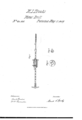
Be it known that I, MERRITT S. BROOKS., of Chester, in the county of Middlesex and State of Connecticut, have invented a new and Improved Drill-Stock or Brace for' Operating Bits for Drilling in Metal or Boring in Wood; and I do hereby declare that the following is a full, clear, and exact description of the same, reference being had to the annexed drawings, making part of this specification, in which- Figure l, is a longitudinal section of my invention. Fig. 2, is a detached end view of the sliding collar. Fig. 3, is a detached end View of the tube and ratchet which are fitted within the sliding' collar.
Similar letters of reference indicate corresponding parts in the several figures.
To enable those skilled in the art to fully understand and construct my invention I will proceed to describe it.
A,represents a screw shaft which is constructed of metal, and of any proper dimensions according to the desired size of the tool. In the outer end of this shaft the bit B, is secured, and the inner end of the screw shaft is-litted with a swivel connection in pressure knob C, as shown clearly in Fig. 1. On the screw shaft A, a metal tube D, is fitted, said tube having an internal female twist or thread corresponding to the twist or screw form of the shaft A, said tube fitting on the shaft and operating precisely the same as a nut. To the outer end of tube D, a ratchet a, is attached. The tube D, is
placed loosely in a socket E, which may be of wood and secured to the tube D, by a screw which passes transversely into the socket, its inner end fitting in a groove c, made circumferentially in the tube D, saidV screw permitting the tube D, to turn within the socket E, but not allowing it to slide longitudinally out from it. This will be clearly understood by referring to Fig. l.
The ratchet a, of the tube D, fits within a recess CZ, in the end of the socket E, and in said recess a stop e, said stop being driven into the socket Y permitting the ratchet a, to turn in one direction only, viz., from left to right.
Theoperation is as follows z-The knob C, is placed against the breast of the operator, or`the palm of the hand is pressed against it' `andthe bit B, applied to its work. c-The operator moves the socket E, by hantl, back and forth on the shaft A, and the tube D, in consequence of the stop e, preventing its rotation from right to left, rotates the shaft A, and bit B, from left to right as the socket E, and tube D, is shoved outward toward the bit B. As the socket and tube is drawn back, the shaft and bit remain stationary, the tube D, turning within the socket E.
By this improvement the bit is made to turn in one direction only, viz., its cutting direction, and the bit will not have its edge a destroyed as has been hitherto the case, by areverse movement of the bit.
I do not claim, broadly, the invention of a drill stock having its shaft made in the.
form of a screw; but
Having thus described my invention, I claim and desire to secure by Letters Patent,
The arrangement and combination with a spiral or screw-shaped shaft A, of a tube D, ratchet (a), and stop (e), within the socket E, as and for the purpose herein shown and described.
MERRITT S. BROOKS. Writnesses SocRATEs DnNisoN, E. W. PARMELEE.
Publications (1)
| Publication Number | Publication Date |
|---|---|
| US24005A true US24005A (en) | 1859-05-17 |
Family
ID=2091775
Family Applications (1)
| Application Number | Title | Priority Date | Filing Date |
|---|---|---|---|
| US24005D Expired - Lifetime US24005A (en) | Drill-stock |
Country Status (1)
| Country | Link |
|---|---|
| US (1) | US24005A (en) |
Cited By (6)
| Publication number | Priority date | Publication date | Assignee | Title |
|---|---|---|---|---|
| US4448140A (en) * | 1982-10-05 | 1984-05-15 | Porter Robert E | Recessed top feed for sewing machines |
| US20120095447A1 (en) * | 2010-10-19 | 2012-04-19 | Occam Scientific, Llc | Apparatus for rotating medical devices, systems including the apparatus, and associated methods |
| US20140373651A1 (en) * | 2013-06-20 | 2014-12-25 | Zedi Canada Inc. | Angular Motion Control System and Method |
| US9107691B2 (en) | 2010-10-19 | 2015-08-18 | Distal Access, Llc | Apparatus for rotating medical devices, systems including the apparatus, and associated methods |
| US11000307B2 (en) | 2010-10-19 | 2021-05-11 | Minerva Surgical Inc. | Apparatus for rotating medical devices, systems including the apparatus, and associated methods |
| US11446050B2 (en) | 2014-04-28 | 2022-09-20 | Minerva Surgical, Inc. | Tissue resectors with cutting wires, hand operated tissue resecting systems and associated methods |
-
0
- US US24005D patent/US24005A/en not_active Expired - Lifetime
Cited By (8)
| Publication number | Priority date | Publication date | Assignee | Title |
|---|---|---|---|---|
| US4448140A (en) * | 1982-10-05 | 1984-05-15 | Porter Robert E | Recessed top feed for sewing machines |
| US20120095447A1 (en) * | 2010-10-19 | 2012-04-19 | Occam Scientific, Llc | Apparatus for rotating medical devices, systems including the apparatus, and associated methods |
| US8845621B2 (en) * | 2010-10-19 | 2014-09-30 | Distal Access, Llc | Apparatus for rotating medical devices, systems including the apparatus, and associated methods |
| US9107691B2 (en) | 2010-10-19 | 2015-08-18 | Distal Access, Llc | Apparatus for rotating medical devices, systems including the apparatus, and associated methods |
| US11000307B2 (en) | 2010-10-19 | 2021-05-11 | Minerva Surgical Inc. | Apparatus for rotating medical devices, systems including the apparatus, and associated methods |
| US20140373651A1 (en) * | 2013-06-20 | 2014-12-25 | Zedi Canada Inc. | Angular Motion Control System and Method |
| US9239101B2 (en) * | 2013-06-20 | 2016-01-19 | Zedi Canada Inc. | Angular motion control system and method |
| US11446050B2 (en) | 2014-04-28 | 2022-09-20 | Minerva Surgical, Inc. | Tissue resectors with cutting wires, hand operated tissue resecting systems and associated methods |
Similar Documents
| Publication | Publication Date | Title |
|---|---|---|
| US410780A (en) | Maurice cah | |
| US24005A (en) | Drill-stock | |
| US2893276A (en) | Automatic tool feeding device | |
| US2792727A (en) | Boring jig | |
| US18918A (en) | Implement fob cutting metal tubes | |
| US29883A (en) | John m | |
| US22195A (en) | Auger for wood | |
| US1008363A (en) | Bit. | |
| US673689A (en) | Center-drilling apparatus. | |
| US25512A (en) | Bung-hole borer and reamer | |
| US29602A (en) | Gas-pipe gutter | |
| US20728A (en) | Hand-drill | |
| US2537274A (en) | Micrometrically adjustable boring tool | |
| US134007A (en) | Improvement in pipe-cutters | |
| US1286644A (en) | Boring and drilling device. | |
| US21960A (en) | Tap for cutting wooden screws | |
| US19829A (en) | Method of attaching expansible cutting-tips to augers | |
| US81402A (en) | John peace | |
| US52106A (en) | Improved wrench and drill | |
| US201372A (en) | Improvement in screw-drivers | |
| US1206363A (en) | Expansible bit. | |
| US136830A (en) | Improvement in brace-drills | |
| US2572280A (en) | Drill stock power drive coupling | |
| US683794A (en) | Angle bit-stock. | |
| US313204A (en) | grooms |