US2387016A - Magnetic polarity changing circuit - Google Patents
Magnetic polarity changing circuit Download PDFInfo
- Publication number
- US2387016A US2387016A US494487A US49448743A US2387016A US 2387016 A US2387016 A US 2387016A US 494487 A US494487 A US 494487A US 49448743 A US49448743 A US 49448743A US 2387016 A US2387016 A US 2387016A
- Authority
- US
- United States
- Prior art keywords
- armature
- spider
- poles
- flux
- motor
- Prior art date
- Legal status (The legal status is an assumption and is not a legal conclusion. Google has not performed a legal analysis and makes no representation as to the accuracy of the status listed.)
- Expired - Lifetime
Links
- 230000005291 magnetic effect Effects 0.000 title description 11
- 241000239290 Araneae Species 0.000 description 29
- 230000004907 flux Effects 0.000 description 22
- 239000000463 material Substances 0.000 description 3
- XEEYBQQBJWHFJM-UHFFFAOYSA-N Iron Chemical compound [Fe] XEEYBQQBJWHFJM-UHFFFAOYSA-N 0.000 description 2
- 239000000696 magnetic material Substances 0.000 description 2
- 238000000034 method Methods 0.000 description 2
- 238000004804 winding Methods 0.000 description 2
- TVEXGJYMHHTVKP-UHFFFAOYSA-N 6-oxabicyclo[3.2.1]oct-3-en-7-one Chemical compound C1C2C(=O)OC1C=CC2 TVEXGJYMHHTVKP-UHFFFAOYSA-N 0.000 description 1
- FYYHWMGAXLPEAU-UHFFFAOYSA-N Magnesium Chemical compound [Mg] FYYHWMGAXLPEAU-UHFFFAOYSA-N 0.000 description 1
- 101100400378 Mus musculus Marveld2 gene Proteins 0.000 description 1
- 241001417524 Pomacanthidae Species 0.000 description 1
- 229910052782 aluminium Inorganic materials 0.000 description 1
- XAGFODPZIPBFFR-UHFFFAOYSA-N aluminium Chemical compound [Al] XAGFODPZIPBFFR-UHFFFAOYSA-N 0.000 description 1
- 238000010276 construction Methods 0.000 description 1
- 229910052742 iron Inorganic materials 0.000 description 1
- 229910052749 magnesium Inorganic materials 0.000 description 1
- 239000011777 magnesium Substances 0.000 description 1
- 230000005389 magnetism Effects 0.000 description 1
- 229910052751 metal Inorganic materials 0.000 description 1
- 239000002184 metal Substances 0.000 description 1
- 229910000679 solder Inorganic materials 0.000 description 1
Images
Classifications
-
- H—ELECTRICITY
- H02—GENERATION; CONVERSION OR DISTRIBUTION OF ELECTRIC POWER
- H02P—CONTROL OR REGULATION OF ELECTRIC MOTORS, ELECTRIC GENERATORS OR DYNAMO-ELECTRIC CONVERTERS; CONTROLLING TRANSFORMERS, REACTORS OR CHOKE COILS
- H02P7/00—Arrangements for regulating or controlling the speed or torque of electric DC motors
- H02P7/03—Arrangements for regulating or controlling the speed or torque of electric DC motors for controlling the direction of rotation of DC motors
-
- H—ELECTRICITY
- H02—GENERATION; CONVERSION OR DISTRIBUTION OF ELECTRIC POWER
- H02K—DYNAMO-ELECTRIC MACHINES
- H02K99/00—Subject matter not provided for in other groups of this subclass
- H02K99/20—Motors
Definitions
- this invention is, for instance, the changing of the direction of rotation of a motor armature. and which is accomplished simply by rotating a simple form of magnetic spider through a small arc.
- the drawing shows a magnetic circuit to produce this result.
- the field structure is of an isolated flux path design.
- the main frame assembly is composed of non-magnetic materials with the exception of the separate and independent flux carrying material co'mpfising the spider and U-shaped isolated polar units and the armature. It is readily seen that a relatively small rotation of the magnetic spider member will reverse the rotation of the armature and that rotation in the opposite direction cause the armature to rotate in the op-' posite direction,
- the armature may have a multi-polar winding for variable speed operation with this circuit arrangement.
- the flux sup-. plied from the spider will have a closed path regardless of the signs of the field poles, or when the spider is placed in such a position that the fluxes are shunted perpendicularly through alternate teeth, it will nullify the flux through the armature by simply changing the direction of -ilux, from -the longitudinal position to a perpendicular shunt position between. alternate teeth of the exciting spider,-thus flux leakage to the air is at an absolute minimum.
- One of the principal objects of this invention is to present a means and method for changin the direction of fluxs in magnetic circuits and the like without reversing switches, or complicated electrical means.
- Another object of equal importance is the means and method of reversing flux paths in electrical. equipment by' a simple mechanicai movement.
- Another object is to provide flux reversing; conditions in electrical devices without producing mechanical or electrical strains upon the material or arrangement of the element in the dedrawing, the subjoined detailed description, the,
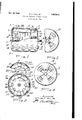
- Fig. 1 shows the invention as applied to an elec.
- Fig. 2 is an elevaticnal view of a part of the end plate of the motor.
- Fig. 3 is a sectional view taken substantially along the line 3-3 of Fig. 1. 4
- Fig. 4 is an elevational view of another end plate of the motor
- r Fig. 5 is a sectional view of'e, portion of the invention taken partly along the line 3-3 of Fig.
- the outer frame or casing of the motoru's indicated at I whichjncludes the cylindrical shell 2 and the metal end plates 3 and t.
- the shell 2 is preferably. made oi some non-magnetic mavterial such as aluminum or some magnesium al-- .103] material, and has its ends rabbeted, as at 5 and e, which is machined to snugly .fit the inner peripheries of the end plates 3 and d; bolts or any other suitable fastening means may be employed to hold the end plates firmly to the shell.
- l and the plate t the integral bearing 8, both of which support and journal the motor shaft Q.
- the pulley or gear end or the shaft has a key slot to.
- the end plate 3 is provided with a plurality of ventilating openings ii, and the plate v s is provided with the openings l2.
- the shaft e supports an armatui is with its commutator l5 and the polar disc, unit or spider member i l.
- the armature or power delivery means or element is keyed to the shaft whereas thespider id is not, this spider is free wheeling on the shaft so that the shaft can freely rotate without being hindered by the spider member.
- the armature as shown, is a lap wound direct current armature with the leads of the armature coils connected in the conventional manner to the varioussegments of the commutator.
- Each flux transfer member should be laminated and have a small head 38 and a large head 3!, the large head being somewhat rectangular inshape on the inner face thereof and the small-head being substantially square on the inner face thereof.
- the large heads form an annular field about the armature whereas the small heads surround the spider I4 and receive their magnetism from the plurality of spider.
- the poles 32; 34, 86 and stare permanently magnetized south poles, whereas poles 33,
- 35, 37 and 39 are permanently magnetized north poles. Any number of poles may be employed, and in this form of the invention, eight poles were thought adequate to clearlyillustrate the inven tion. Since the spider has eight poles, the iiulr transfer members also-are eight in number.
- a direct currentznotor with a shunt field can have its rotation reversed by merely changing the polarity of the field poles. Since the armature is wound in order to give the coils thereon a high impedance, the motor can be leitin the line circuit with safety. This being the case, the motor can be stopped by merely moving the handle 59 so as to place the spider poles in the positions shown in Fig.3 relative to the "small heads 29 to 28.
- the spider can be rotated-by hand, or by remote ment with certain carrier poles to be presently explained.
- a curved slot is in the side at the means and shift the poles of the spider in aline
- the spider need not be changed entirely except that it should besoit iron and laminated. With such a change in the spider, each pole would have a field coil connected Having thus described my invention, what is poles on the v of?
- poles numbered 32 to 39 inclusive which are transfer means having pole pieces at the ends thereof, the pole pieces at one of the ends of the means surrounding the element and the pole pieces at the other ends of the means surrounding the unit, said polar unit having means for shifting it rotativ'ely so as to change the flux direction in the transfer means and in the power delivery element,
- the unit has a hub with a plurality of radially extended arms for supporting the pole faces, and a control handle means fixed to a portion of the unit for shifting the unit with respect to the transfer means;
- an electrical device having a housing with a shaft therethrough, an armature keyed to the shaft and a polar unit journalled on said shaft for free shifting thereon, a plurality of flux transfer members spaced apart around the periphery of the armature and the'unit and fixed to an inner surface of the housing, means concentric with the shaft and keyed thereto for conducting electrical currents between the armature and an outside circuit, and said transfer means having end pieces slightly space from the uter surfaces of the unit and the armature.
Landscapes
- Engineering & Computer Science (AREA)
- Power Engineering (AREA)
- Iron Core Of Rotating Electric Machines (AREA)
Description
Oct. 16, 1945. c, HALL, JR 2,387,016
MAGNETIC POLARITY CHANGING CIRCUIT Filed July 13, 1943 fA VEA/Tb? MLAED C. HaLL,-a;e.
Patented a. 16, 1945 UNITE smrss PATENT MAGNETEG PQLAE'ETY Wiiiard 0. Hall, Jr., has Angeles, Calif., assignor to Helen J. Hall, Jr., Los Angeles, Qalif,
Application Juiy 33, 1943,- Serial No. MMMS'I 4 Claims. (or. 172-46) this invention is, for instance, the changing of the direction of rotation of a motor armature. and which is accomplished simply by rotating a simple form of magnetic spider through a small arc. The drawing shows a magnetic circuit to produce this result. It will be noted that in direct contrast to the conventional field flux paths employed in electrical motors, generators and the like, that the exciting fiux'is supplied to the armature from a spider having alternate mag netic poles which may be of a permanent magnetic material or electromagnetically excited through a coil system, but that the 'flux paths are directed longitudinally through isolated magnetic units in the barrel assembly or frame of the motor, to
pole projections, which produces the flux at right an les to the flux in the units, then down through the armature and returning through the adjacent isolated U-shaped magnetic .units. to be noted that the field structure is of an isolated flux path design. In this particular application, the main frame assembly is composed of non-magnetic materials with the exception of the separate and independent flux carrying material co'mpfising the spider and U-shaped isolated polar units and the armature. It is readily seen that a relatively small rotation of the magnetic spider member will reverse the rotation of the armature and that rotation in the opposite direction cause the armature to rotate in the op-' posite direction,
Many combinations are possible with spiders and isolated flux transferring members or units so thatsmall movements clockwise or anti-clockwise of the spider will cause a reversal of the armature. The armature may have a multi-polar winding for variable speed operation with this circuit arrangement. v
It is of importance to note, that the flux sup-. plied from the spider will have a closed path regardless of the signs of the field poles, or when the spider is placed in such a position that the fluxes are shunted perpendicularly through alternate teeth, it will nullify the flux through the armature by simply changing the direction of -ilux, from -the longitudinal position to a perpendicular shunt position between. alternate teeth of the exciting spider,-thus flux leakage to the air is at an absolute minimum. By providing the It is armature with high impedance windings, the motor can safely be allowed to remain in the circuit at all times.
is apparent from the foregoing, that the advantages of this flux interchanging arrangeent is varied and many, inasmuch as the requirements for complete and efficient change of polarity may be secured by a slight movement of a magnetic spider in a back and forth movement,
One of the principal objects of this invention is to present a means and method for changin the direction of fluxs in magnetic circuits and the like without reversing switches, or complicated electrical means.
Another object of equal importance is the means and method of reversing flux paths in electrical. equipment by' a simple mechanicai movement.
Another object is to provide flux reversing; conditions in electrical devices without producing mechanical or electrical strains upon the material or arrangement of the element in the dedrawing, the subjoined detailed description, the,
preamble of this specification and the. appended claims.
Applicant is about to illustrate and describe one of the forms of his invention in order to teach one how to make and use the same, but it is to be understood that the drawing and description thereof are not to limit the invention in any sense whatsoever, except as limited by the appended claims.
In the drawing: Fig. 1 shows the invention as applied to an elec.
tric motor, the motor being shown in eleva tion with parts thereof being broken away to show internal elements and some of the elements in section.
Fig. 2 is an elevaticnal view of a part of the end plate of the motor.
plate 8 acts as a guide for thehandle and limits,
its movement. v I I Spaced equally around the armature and the spider are a plurality of arms, pole members or flux transfer means 2| to 28 inclusive, all of which are partially embedded in annularly spaced slots 2% which are cut-into the inner surface the shell 2. Bolts or any other suitable means may i be used to securely hold the arms in their respec- Fig. 3 is a sectional view taken substantially along the line 3-3 of Fig. 1. 4
Fig. 4 is an elevational view of another end plate of the motor, and r Fig. 5 is a sectional view of'e, portion of the invention taken partly along the line 3-3 of Fig.
1, but showing certain elements thereof in a diflerent position.
The outer frame or casing of the motoru's indicated at I, whichjncludes the cylindrical shell 2 and the metal end plates 3 and t. The shell 2 is preferably. made oi some non-magnetic mavterial such as aluminum or some magnesium al-- .103] material, and has its ends rabbeted, as at 5 and e, which is machined to snugly .fit the inner peripheries of the end plates 3 and d; bolts or any other suitable fastening means may be employed to hold the end plates firmly to the shell. l and the plate t the integral bearing 8, both of which support and journal the motor shaft Q. The pulley or gear end or the shaft has a key slot to. The end plate 3 is provided with a plurality of ventilating openings ii, and the plate v s is provided with the openings l2.
The shaft e supports an armatui is with its commutator l5 and the polar disc, unit or spider member i l. The armature or power delivery means or element is keyed to the shaft whereas thespider id is not, this spider is free wheeling on the shaft so that the shaft can freely rotate without being hindered by the spider member. The armature, as shown, is a lap wound direct current armature with the leads of the armature coils connected in the conventional manner to the varioussegments of the commutator. The exact "nature of the armature is unimportant as v there is no claim to any particular armature construction as it, per so, does not enter into the invention except that the armature must be sultably wound and connected for oneration in a shunt connecteddireet current motor. 7 One set oi brushes is is shown positioned upon the coinmutator, and obviously, at least another set would vbeemployed. in conjunction therewith at a point diametrically opposite. The terminal block with tie two terminals 96 and ii are shown which should be conneomd to any .source of suitable current supply so that the armature can be properly energized. Any sort of suitable bracket means (not shown) may be employed to support the motor or connect same with some machine which is to be operated or controlled thereby,
mtween the bearings of the armature and polar spider is the collar or ring it which is well lubricated and spaces the armature and spider apart so that the spider can freely rotate on the shaft and independent of its motion. A handle control means, or lever leis screwed into the side of the spider id and rigidly held thereto so that The end plate 3 has the integral bearing,
tive slots. Each flux transfer member should be laminated and have a small head 38 and a large head 3!, the large head being somewhat rectangular inshape on the inner face thereof and the small-head being substantially square on the inner face thereof. The large heads form an annular field about the armature whereas the small heads surround the spider I4 and receive their magnetism from the plurality of spider.
The spiderhas a plurality equally spaced and have faces which substan= tially register, or nearly so, with the faces of the-small flux transfer heads 38. As indicated by letters, the poles 32; 34, 86 and stare permanently magnetized south poles, whereas poles 33,
35, 37 and 39 are permanently magnetized north poles. Any number of poles may be employed, and in this form of the invention, eight poles were thought suficient to clearlyillustrate the inven tion. Since the spider has eight poles, the iiulr transfer members also-are eight in number.
From the foregoing, it is clear that none of the small flux transfer heads 25 to 28 inclusive become south or north poles when the solder (permanent poles) are in the position shown in Fig. 3 of the drawing. But, however, when the handle it is operated so as to bring the poles of i the spider into alinement with the small heads of the flux transfer heads, the heads opposite the various poles on the spider will have exact opnosite polarity than the poles they are in aline= ment with, therefore, whenever it is desired to re= verse the direction of the motor armature, it is only necessary to move the handle is and change the polarity of the small heads and hence change the polarity 0:. the large heads 3i. It is well known that a direct currentznotor with a shunt field can have its rotation reversed by merely changing the polarity of the field poles. Since the armature is wound in order to give the coils thereon a high impedance, the motor can be leitin the line circuit with safety. This being the case, the motor can be stopped by merely moving the handle 59 so as to place the spider poles in the positions shown in Fig.3 relative to the "small heads 29 to 28.
the spider can be rotated-by hand, or by remote ment with certain carrier poles to be presently explained. a curved slot is in the side at the means and shift the poles of the spider in aline In the event that electromagnetic poles are preferred upon the poles of the spider id in place of the permanent magnets,-the spider need not be changed entirely except that it should besoit iron and laminated. With such a change in the spider, each pole would have a field coil connected Having thus described my invention, what is poles on the v of? projecting poles numbered 32 to 39 inclusive which are transfer means having pole pieces at the ends thereof, the pole pieces at one of the ends of the means surrounding the element and the pole pieces at the other ends of the means surrounding the unit, said polar unit having means for shifting it rotativ'ely so as to change the flux direction in the transfer means and in the power delivery element,
2. The device recited in claim 1 wherein the unit has a hub with a plurality of radially extended arms for supporting the pole faces, and a control handle means fixed to a portion of the unit for shifting the unit with respect to the transfer means;
3. In an electrical device having a housing with a shaft therethrough, an armature keyed to the shaft and a polar unit journalled on said shaft for free shifting thereon, a plurality of flux transfer members spaced apart around the periphery of the armature and the'unit and fixed to an inner surface of the housing, means concentric with the shaft and keyed thereto for conducting electrical currents between the armature and an outside circuit, and said transfer means having end pieces slightly space from the uter surfaces of the unit and the armature.
4. The device recited in claim 3 wherein the housing encloses the armature and unit and the .unit through the slot for exterior operation of the holar unit.
Priority Applications (1)
| Application Number | Priority Date | Filing Date | Title |
|---|---|---|---|
| US494487A US2387016A (en) | 1943-07-13 | 1943-07-13 | Magnetic polarity changing circuit |
Applications Claiming Priority (1)
| Application Number | Priority Date | Filing Date | Title |
|---|---|---|---|
| US494487A US2387016A (en) | 1943-07-13 | 1943-07-13 | Magnetic polarity changing circuit |
Publications (1)
| Publication Number | Publication Date |
|---|---|
| US2387016A true US2387016A (en) | 1945-10-16 |
Family
ID=23964690
Family Applications (1)
| Application Number | Title | Priority Date | Filing Date |
|---|---|---|---|
| US494487A Expired - Lifetime US2387016A (en) | 1943-07-13 | 1943-07-13 | Magnetic polarity changing circuit |
Country Status (1)
| Country | Link |
|---|---|
| US (1) | US2387016A (en) |
Cited By (1)
| Publication number | Priority date | Publication date | Assignee | Title |
|---|---|---|---|---|
| US2999952A (en) * | 1960-06-10 | 1961-09-12 | Dorothy C Hammes | Synchronous motor |
-
1943
- 1943-07-13 US US494487A patent/US2387016A/en not_active Expired - Lifetime
Cited By (1)
| Publication number | Priority date | Publication date | Assignee | Title |
|---|---|---|---|---|
| US2999952A (en) * | 1960-06-10 | 1961-09-12 | Dorothy C Hammes | Synchronous motor |
Similar Documents
| Publication | Publication Date | Title |
|---|---|---|
| US3671841A (en) | Stepper motor with stator biasing magnets | |
| US2968755A (en) | Magnetic motor | |
| US3091728A (en) | Electric motors | |
| US3018395A (en) | Tachometer generator | |
| US1227185A (en) | Induction device. | |
| RU2180766C2 (en) | Electronically commutated two-phase reluctance machine | |
| US3504253A (en) | Rotary stepping motor having a d-c winding and a pulsed winding | |
| US2760093A (en) | Electric generator | |
| US3253169A (en) | Synchronous motors | |
| US4132911A (en) | Electric motor with permanent magnets combined with electromagnets | |
| US3715643A (en) | Electrically driven motor | |
| US2387016A (en) | Magnetic polarity changing circuit | |
| JP5281768B2 (en) | Planetary magnetic pole rotating machine | |
| US3375383A (en) | Magnetic drive device | |
| US3624439A (en) | Electromechanical energy converter with low-inertia specially wound coil | |
| US592244A (en) | Electrical power transmission | |
| US3178599A (en) | Permanent magnet d.c. torquer | |
| US1833914A (en) | Electric motor | |
| USRE25445E (en) | fredrickson | |
| NL6913200A (en) | ||
| US3293457A (en) | Brushless d.c. motor provided with hall-effect devices | |
| GB687199A (en) | Improvements in and relating to step-by-step electric motors | |
| US2271087A (en) | Electromagnetic transmission | |
| US2408641A (en) | Dynamoelectric machine | |
| US2327341A (en) | Remote control system |