US2367775A - Apparatus for feeding material - Google Patents
Apparatus for feeding material Download PDFInfo
- Publication number
- US2367775A US2367775A US459979A US45997942A US2367775A US 2367775 A US2367775 A US 2367775A US 459979 A US459979 A US 459979A US 45997942 A US45997942 A US 45997942A US 2367775 A US2367775 A US 2367775A
- Authority
- US
- United States
- Prior art keywords
- conveyer
- feeding
- shaft
- circuit
- conductor
- Prior art date
- Legal status (The legal status is an assumption and is not a legal conclusion. Google has not performed a legal analysis and makes no representation as to the accuracy of the status listed.)
- Expired - Lifetime
Links
- 239000000463 material Substances 0.000 title description 258
- 239000004020 conductor Substances 0.000 description 117
- 230000008859 change Effects 0.000 description 48
- 230000001105 regulatory effect Effects 0.000 description 41
- 230000002441 reversible effect Effects 0.000 description 15
- 230000000694 effects Effects 0.000 description 13
- 230000007246 mechanism Effects 0.000 description 11
- 238000005303 weighing Methods 0.000 description 11
- 230000008878 coupling Effects 0.000 description 7
- 238000010168 coupling process Methods 0.000 description 7
- 238000005859 coupling reaction Methods 0.000 description 7
- 230000001276 controlling effect Effects 0.000 description 6
- 230000001186 cumulative effect Effects 0.000 description 5
- 230000002829 reductive effect Effects 0.000 description 5
- 230000009471 action Effects 0.000 description 4
- 238000010276 construction Methods 0.000 description 4
- 239000002783 friction material Substances 0.000 description 4
- 238000009877 rendering Methods 0.000 description 4
- 230000005284 excitation Effects 0.000 description 3
- 238000010586 diagram Methods 0.000 description 2
- 210000005069 ears Anatomy 0.000 description 2
- 208000017740 grade III prostatic intraepithelial neoplasia Diseases 0.000 description 2
- 239000012212 insulator Substances 0.000 description 2
- 230000007935 neutral effect Effects 0.000 description 2
- 230000002093 peripheral effect Effects 0.000 description 2
- XXPDBLUZJRXNNZ-UHFFFAOYSA-N promethazine hydrochloride Chemical group Cl.C1=CC=C2N(CC(C)N(C)C)C3=CC=CC=C3SC2=C1 XXPDBLUZJRXNNZ-UHFFFAOYSA-N 0.000 description 2
- 239000011435 rock Substances 0.000 description 2
- 206010043268 Tension Diseases 0.000 description 1
- 241000746181 Therates Species 0.000 description 1
- 230000005611 electricity Effects 0.000 description 1
- 230000005484 gravity Effects 0.000 description 1
- 230000000977 initiatory effect Effects 0.000 description 1
- 230000000670 limiting effect Effects 0.000 description 1
- 239000003550 marker Substances 0.000 description 1
- 230000001681 protective effect Effects 0.000 description 1
- 230000009467 reduction Effects 0.000 description 1
- 230000000717 retained effect Effects 0.000 description 1
- 230000001360 synchronised effect Effects 0.000 description 1
Images


Classifications
-
- G—PHYSICS
- G01—MEASURING; TESTING
- G01G—WEIGHING
- G01G11/00—Apparatus for weighing a continuous stream of material during flow; Conveyor belt weighers
- G01G11/08—Apparatus for weighing a continuous stream of material during flow; Conveyor belt weighers having means for controlling the rate of feed or discharge
Definitions
- This invention relates to the feeding of material, and relates particularly to mean to automatically regulate the flow of a stream of material to feed material at the rate of a predetermined weight from a source of supply of the material to a place of use or storage of the ma- *erial.
- Itis another object of the invention to provide in material feeding means including a travelling conveyer adapted to travel at a speed to feed ma-- terial at the rate of a predetermined weight from a source of supply of the material, means opera.- tive at successive intervals to detect any'variation in the rate of feed of the material by the conveyer during said intervals, and vary the speed of travel of the conveyer to feed material in inverse pro-portion to any variation in the rate of feed of the material by the conveyer during said intervals.
- Another object of the invention is to provide in material feeding means including a travelling conveyer and means to counterbalance material of predetermined weight on the conveyer, variable speed operating means to actuate the conveyer to travel at a speed to feed material from a source of supply at the rate of the weight counterbalanced on the convey
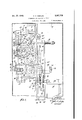
- Figure 1 is a diagrammatic representation of an embodiment of the invention showing in side elevation a material conveyer and means to counterbalance material of predetermined weight thereon, and showingin perspective means to integrate and register the cumulative weight of the material fed by the conveyer and circuit making means actuated thereby connected in circuit with and controlling the operation of means for timing the feeding of the material and the operation of circuit closing means for controlling the operation of means to regulate the operation and feeding of material by the conveyer.
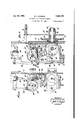
- Figure 2 is a front elevation of a portion of the register and circuit making means actuated by the integrating means to control the operation of the timing means.
- Figure 3 is a view looking at the top of Figure 2.
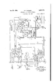
- Figure 4 is a wiring diagram ShOWiIlg the electrical hook-up of the conveyer actuating motor with its source of power and the electrical connections between the circuit making meansactuated by the integrating means and the means for controlling the operation of the timing means and circuit closing means for controlling the operation of a reversible motor for actuating a rheostat device for regulating the operation of the conveyer actuating motor.
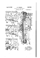
- Figure 5 is a front elevation of the means for timing the feeding of material by the conveyer and means to cooperate therewith to detect any change in the rate of feeding the material and actuating the circuit closing means for and controlling the operation of the rheostat actuating motor.
- Figure 6 is an elevational view, partly in section and partly broken away, looking at the right of Figure 5.
- Figure 7 is a sectional view taken on the line 1-1 of Figure 5 looking in the direction of the arrows.
- Figures 8, 9 and 10 are sectional views taken on the lines 88, 9-9 and l9-l0 of Figure 5 looking in the direction of the arrows.
- Figure 11 is a sectional view taken on the line H--H of Figure 12 looking in the direction of the arrows, and showing means to lock the timing means in actuated position during the actuation of the detecting and circuit closing means for the reversible motor.
- Figure 12 is a sectional view taken on the line
- Figure 13 is a sectional view taken on the line l3-!3 of Figure 5 looking in the direction of the arrows.
- Figures 14 and 15 are sectional views taken on the lines l4
- the material is fed in a continuous stream by a conveyer V of the endless belt type passing around and supported by pulleys or drums IE5 and I! and the conveyer actuated or driven to travel in the direction indicated by the arrow by a motor M operatively connected to the drum 5 by a sprocket chain passing around a sprocket wheel rotatable with the drum l6 and a sprocket wheel fixed on the shaft of motor M, or of a speed reducing mechanism associated therewith, as shown at 18.
- the motor M is a direct current motor connected by conductor G, G" in circuit with a motor-generator 3- ( Figure 4) connected to a source of alternating electric current, the conductor G" having an overload and low voltage protective device interposed therein, as shown at 18' in Figure 4, the motor M also being connected to a. separate source of direct electric current excitation, hereinafter described.
- Material to be fed by the conveyer is supplied to the conveyer from a suitable source of supply, and shown as discharged onto the conveyer from the outlet of a hopper or bin H, the area of the bin outlet being adapted to be varied, and thereby the discharge of the material from the hopper or bin H, by an adjustable gate 2 I.
- the material is fed by the conveyer at the rate of a predetermined weight, and for this purpose means are provided for counterbalancing material of a predetermined weight on the conveyer.
- this means comprises a roller 22 rotatably supported at the ends by a pair of links 23 pivotally suspended from one end of a pair of arms 24 fixed at the opposite ends to and extending horizontally from a shaft 25 rotatably supported in bearings mounted on a fixed support, the roller extending transversely below and supporting a portion of the lower stretch of the conveyer intermediate the conveyer supporting drum l6 and the bin H.
- a weighing lever 26 of greater length than the lever arms 24 is fixed at one end to the shaft 25 to extend parallel to the lever arms 24 and at the opposite end pivotally supported by a rod 27 having a hook at one end engaging a clevis 28pivotally connected to said weighing lever and the opposite end of the rod pivotally connected to the short end of a beam 29 fulcrumed upon a fixed support 29'.
- the material on the conveyer is automatically counterbalanced and the beam 29 is caused to be deflected from the horizontal or balanced position in proportion to the load on the conveyer by a plunger operating in a dash pot 30 mounted on a fixed part, the plunger being carried by a rod pivotally connected to and suspended from the long end of the beam. as at 3
- counterpoise weights 32 are applied to the plunger rod of the dash pot.
- the integrating means comprises a belt 33 supported by and passing around a series of four pulleys 34 mounted in a casing, only a portion of which casing is shown, to rotate on vertical axes and whereby the belt is adapted to travel in a rectangular path in a horizontal plane, the belt being driven at a speed in correspondence with one of the quantities, the speed of travel of the conveyer, to be integrated, and is driven from the conveyer by a sprocket chain 35 passing around a sprocket wheel fixed on the shaft of a roller 36 frictionally engaging and driven from the lower stretch of the conveyer, and around a sprocket wheel 31 fixed on a shaft having a bevel pinion connection with a shaft of one of the pulleys 34, as shown at 38.
- a carrier in the form of a disk 39 carries a series of integrating rollers or wheels 40 mounted on the disk to independently rotate about axes tangential to the periphery of the disk, and the carrier is supported in a frame 4
- is pivotally supported, as at 42, to have adjustment on an axis transversely of the axis of rotation of the carrier 39 and the travel ofthe belt 33, whereby the carrier is adapted to be positioned to extend at a right angle, and different angles less than a right angle, relative to the plane of travel of said belt.
- the carrier is positioned at a right angle to the travel of the belt 33 with diametrically opposite integrating wheels 40 contacting opposite stretches of the belt said wheels are rotated about their axes and no rotation is imparted to the carrier or disk.
- the belt exerts a force on the integrating wheels contacting the belt perpendicular to the plane of rotation thereof and thereby produces rotation of the carrier or disk 39 across the face of the belt, the following rollers coming into action with the belt in orderly procession and imparting continuous rotation to the carrier.
- the carrier is adapted to be adjusted to take different positions in angular relation to the travel of the belt 33 l by the load or weight of the material on the conveyer.
- is connected to the beam to participate in the deflection thereof out of the horizontal or no loadposition in direct proportion to the weight of the material on the conveyer by a rod 43 pivotally connected at one end to the end of the beam and connected at the opposite end, as at 44, to the frame 4
- a complete revolution is imparted to the carrier or disk 39 by the feeding of a quantity of material of predetermined weight over the roller 22 or weighing point, and each revolution of the .carrier 39 is, therefore, representative of a quantity, or the weight, pounds or tons, of material fed by the conveyer.
- a register or counter R of conventional form is mounted on the frame 4
- the conveyer is adapted to feed material from the bin H and off from the end of the conveyer at the rate of the predetermined weight determined by the quantity of material discharged onto the conveyer from the bin controlled by the adjustable gate 2
- means are provided to vary the excitation of the field of and actuation of the motor M for driving the conveyer, and as shown comprises a rheostat device, shown in a conventional manner at S in Figures 1 and 4, and including potentiometer and field sections.
- the motor M is connected by a conductor IBZ) to a terminal contact of the field section of the rheostat and by conductors l8 and to the terminal contact of' the potentiometer section of the rheostat, said conductors l8 and? 20' having a voltage limiting rheostat l8 interposed.
- the motor G is connected by conductor G to the terminal: contacts at the ends of the.
- potentiometer and field sections of the rheostat opposite the ends to which the conductors N
- the circuit maker 49 is set whereby during the normal operation.
- the motor M is connected to the separate source of direct electric current excitation by a conductor 29 connected to the conductor 20 and a conductor G connected to the conductor G
- a conductor 29 connected to the conductor 20
- a conductor G connected to the conductor G
- This means herein termed a rate timer, shown in front elevation in Figure 5, is mounted and enclosed in a housing T, and relays connected in circuit with and for controlling operating circuits of the rate timer are carried. in a box or casing T, and the operation of said relays is controlled from the integrating means by the feeding of proportionate portions of material and actuation of circuit closing means thereby at successive intervals rendering active the timing means and the detecting means and circuit closing means to connect a reversible pilot motor M in one of two-operating circuits for actuating the circuit maker 49 of the rheostat device Sconnected to the shaft of said motor M, or a speed reducing means combined therewith, as shown in Figures 1 and 4.
- the timing means ( Figure 5) comprises a pair of cum wheels 59, 53 fixed 'to and spaced axially of a shaft the shaft being journaled at oneend I by an anti-friction bearing in a bearing member fixed to and extendingforwardly of an intermediate portion of a bracket 53 ( Figures 14 and 15) mounted on the face of a mounting plate P supported in vertical position in the housing T, the bracket being of a length equal to the width extending transversely of the. mounting plate P and having the opposite ends flanged laterally to extend at a right angle and in the same direc' tion from the body of the bracket, as at 53'-and 53",'and the timing cam shaft 5
- the mounting plate P is supported from and in spaced relation to the rear wall of the housing T by studs 6
- the shaft with the cam wheels is rotated by a spring 54 in the direction indicated by the arrow in Figure 5, and said rotation of the shaft is limited by a pin fixed in and extending laterally from a collar fixed on the shaft 5
- the spring 54 is attached at one end to a stud 56 having an adjustable threaded connection with a bracket 51 fixed to and extending laterally from the mounting plate P and the stud secured in adjusted position by a nut threaded onto the stud abutting the bracket.
- the opposite end of the spring is attached to a cable 51' passing over a flanged wheel 58 rotatable on a shaft 59' and the opposite end portion of the cable having two or more turns around a flanged sleeve 5! fixed on the timing cam shaft 5
- is rotated in a direction opposite to that indicated by the arrow by suitable driving means, and shown as comprising a friction disk D fixed to head 63 ( Figure 15) on the end of a shaft 64 journaled by antifriction bearing 64 in a hub 65 of a plate 65', and the shaft with the disk held against axial movement by the disk carrying head 63 abutting one bearing and a collar 68 fixed on the outer end of the shaft abutting the other bearing.
- the late 65 has a pair of perforated arms 81 extending downwardly from the lower end thereof adjacent the opposite side edges and laterally at a right angle relative to the face of the plate, and is pivotally supported by said arms from the mounting plate P by a pin 68 engaging the perforations in the plate arms 61 and in openings in ears extending laterally from lugs p ojecting downwardly from the lower end of the mounting plate P intermediate the side edges thereof, and said ears engaging within the plate arms 61, as shown at 69 in Figures 5 and 6, whereby the plate 65' is adapted to have pivotal movement toward and away from the mounting plate.
- the plate 85 is yieldingly urged in a direction toward the mounting plate P by a spring 10 coiled about a stud fixed at one end in and extending rearwardly from the mounting plate, said stud extending through an opening in the plate 65 of larger diameter than the stud and the spring confined between the plate 65 and nuts threaded onto the end of the stud, as shown in Figure 6 and 15.
- the friction disk is rotated by a synchronous motor M" through a pinion 12 fixed on the motor shaft meshing with a gear 13 rotatable on a stud I4 fixed at one end in and extending laterally from the plate 65, and a pinion 15 rotating with the gear 13 meshing with a gear 16 mounted on and rotatable with the disk carrying head 83.
- the rotation of the friction disk is transmitted to a friction wheel W mounted on a shaft 11 to rotate with and have axial adjustment on said shaft. as by a key '18 fixed in the shaft slidably engaging a keyway in the hub of the friction wheel.
- the shaft 11 is journaled at one end, as by an anti-friction bearing, in a bearing 19 fixed on one of a pair of brackets 80 fixed by angle brackets 8
- a second friction wheel W is driven from the friction disk for a purpose to be hereinafter described, said wheel being mounted on a shaft 84 to rotate with and have axial adjustment on said shaft, as by a key fixed in the shaft slidably engaging a keyway in the hub of the friction wheel the same as the mounting of the
- the friction wheels may be of suitable construction, and as shown, each wheel comprises an annular member of friction material mounted on a hub member 85 in juxtaposed relation to a flange at an end of the hub member and releasably secured thereto by an annular member and screws, as shown at 88.
- the shaft 84 is journaled at one end by an anti-friction bearing in the bearing member 82 coaxially of the shaft 11 and at the opposite end in a bearing member similar to the bearing member 19 on the other bracket 80.
- the wheels are adjusted radially of the friction disk and by the adjustment of the friction wheel W radially inwardly on the friction disk the other friction wheel W is adjusted radially outwardly on the disk, and by adjustment of the wheel W radially outwardly on the disk the wheel W is adjusted radially.inwardy on the disk.
- a shifter 81 is provided for each friction wheel in which the friction wheels are rotatably mounted by anti-friction bearings engaging a portion of reduced diameter of the wheel hub, as at 88, and the friction wheels retained in operative connection with the shifters by washers 89 secured by screws to the end of the hub members at the outer side of the anti-fric tion bearings, as shown at the left in Figure 13.
- a shaft 80 having two diameters is rotatably mounted in the bearing member 82 andthe brackets 80, the portion of larger diameter being screw threaded and the shifter for the friction wheel W having a hub with a screw threaded bore for threaded engagement with the threaded portion of the shaft, as at 9
- the shaft 90 is rotated to adjust the shifter for the wheel W on the shaft by a crank 92 ( Figure 5) adapted to he removably connected to a shaft 93 ( Figures 7 and 13) rotatably mounted in an angle portion of an angle bracket 94 mounted on a laterally extending boss on the one bracket 80 concentric of the shaft 90 and the shafts 90, 93 operatively connected by a bevel pinion on the shaft 93 meshing with a bevel pinion on the end of shaft 90, as at 95.
- a bell crank lever 96 is pivotally supported at the angle portion on a headed stud fixed in a rib extending downwardly and longitudinally of the member 83, as shown at '91 in Figure 15.
- One arm of said lever has a slot therein having the inner end curved laterally and the slot engaged by a roller on a stud fixed in the shifter 81 for the friction wheel W, as at 98 in Figure 5, and the other lever arm has a slot therein curved slightly inward at the outer end and engaged by a roller on a stud fixed in the shifter for the friction wheel W, as at 98.
- the slots in the lever arms are arranged so that when wheel W is adjusted radially outward on the friction disk, wheel W will be adjusted radially inward on the friction disk, and whereby wheel W will be rotated in a direction reverse to and at a reduced speed proportional to the speed of rotation of the friction wheel W.
- the rotation of the friction wheel W and timing cam shaft 5! is proportional to the speed of travel of the conveyer to feed material at the rate of a predetermined weight.
- the rate timer is preset to adjust the friction wheel W on the friction disk to be rotated at a speed proportional to the speed of travel of the conveyer, and to indicate the setting of the rate timer and the rate of feed of material by the conveyer a scale 09, graduated in tons per hour, is provided, said scale being mounted on the bearing member 82 and the bracket 80 in which the one end of the shaft TI is journaled, as shown in Figure 5.
- a pointer I is adjustable relative to the scale effected by the adjustment of the friction wheels, and as shown in Figure said pointer is arranged on the stud carrying roller 98 engaging the slot in and connecting the one arm of lever 9.6 to the shifter N for the friction wheel W.
- the crank 92 for adjusting the shifter adjusting shaft 90 is disposed exterior of the housing T and is adapted to be extended through an opening in said housing to removably connect it to the shaft 93, and to observe the adjustment of the pointer I00 relative to the scale 99 and thereby the setting of the rate timer the housing is provided with a window ml.
- clutch mechanism comprising a shaft I02 mounted to have axial adjustment in a pair of bearings I03 which in turn are mounted in bushings I04 having an annular flange at one end mounted in openings in bosses on the brackets 80 with the flanged end extending laterally from said brackets.
- a combined clutch member and gear I05, I05 is mounted by an anti-friction bearing on each bushing I04 between the bushing flange and the bracket bosses with an interposed Washer, as clearly shown in Figure '7.
- the outer end or face of said clutch and gear members has an annular member I06 of friction material secured thereto, as by countersunk screws.
- the shaft I02 is mounted axially in said clutch and gear members to have axial adjustment which is limited by a pin and slot connection between the shaft and one of the bushings I04, as at I01.
- Clutch members I08, I03 are'rotatably mounted by anti-friction bearings on the reduced ends of said shaft between the membersof friction material I06 and collars I09 fixed on the outer ends of the shaft.
- Each of said clutch members I08, I08 has a pinion I I0, IIO fixed on the outer end thereof. teeth of clutch member I05 mesh with a gear III fixed on the outer end of shaft TI whereby the clutch member I05 is driven from the shaft TI.
- the timing cam shaft is driven through the pinion I I0 meshing with a gear II2 fixed on said shaft.
- the clutch shaft I02 is yieldingly urged in a direction to engage clutch member I08 with clutch member M5 by a'spring II3 coiled about the shaft and confined between the bushing I04 on Which the clutch member is mounted and a collar II4 fixed on said shaft.
- the clutch shaft is normally positioned with the clutch members I08, I08 out of engagement with the clutch members I05, I05 by a pivoted latch H5 engaging a collar H5 fixed on the clutch shaft.
- the latch is released from said collar IIE to permit actuation of the clutch shaft to engage clutch member I08 with clutch member I05 to couple the timing cam shaft to the shaft of friction wheel W by the energizing of a solenoid magnet I to the core of which magnet the latch is connected by adjustable connecting means In pivotally connected to the latch and the magnet core, as shown in Figures 5 and 14.
- the solenoid I is connected in circuit'with a source of electric energy having normally open circuit closing means interposed in the circuit thereof adapted to be actuated to close the circuit and energize the solenoid by the feeding of a proportional portion of material of predetermined weight by the conveyer.
- one terminal of the solenoid I is connected by a conductor 8 to a lead-in wire 1 connectedto a source of electric energy, and the other terminal of said solenoid I connected by a conductor 8 through contact makers g and h of relays A and B, for a purpose to be hereinafter described, with a conductor 7 connected to one terminal of a normally circuit opening switch I I8, the other terminal of which switch is connected byconductor J" to the lead-in wire 1.
- the friction disk rotating motor M is also connected in circuit with the conductors l, l.
- the switch H8 is actuated to circuit closing position at successive intervals from the rotation of the integrating disk 39 by the feeding of proportionate portions of material of predetermined weight.
- this switch H8 is mounted on extensions of the front and rear walls of the register or counter and the switch actuator H9 is actuated by a pin I20 adjustably carried by an arm I2I fixed on a rock shaft I22; rotatable in the front and rear wall extensions of the register casing, and said shaft rocked by a roller I23 rotatably carried at one end of a lever I24fixed at-the opposite end on the rock shaft following a three-hump cam I25 fixed on the'shaft 46 on which the register actuating pinion 48 is mounted.
- Relay B is connected in circuit with lead in conductors Z, 1' through circuit making contact 9 associated with relay A.-by conductor h connected to one terminal of the coil of relay B and the other terminal of said relay coil connected by conductor 71 to the conductor 1.
- the circuit of solenoid I is closed through the switch I I8 and the first electrical impuls is sent out initiating the operation of the rate timer, the circuit of relay B is also closed, but as said relay is of the inertia type the actuation of'the contact maker h tocircuit opening position is de-. layed for a sufficient interval of, time to' effect energization of the solenoid-I.
- the gear 4 As stated, the friction wheel W and the timing cam shaft I are rotated at a speed proportional to the speed of travel of the conveyer to feed material at the rate of the predetermined weight indicated by the pointer IUD on the scale 99, and whereby a proportionate portion of material is fed by a predetermined length of conveyer travel during a predetermined interval of time.
- cam wheels 50, 50 are rotated with the timing cam shaft 5
- timing cam shaft will be rotated through an arc of something less than 180 degrees due to the rate of feed of the conveyer bein too high to feed material at the predetermined rate, and should the time for feeding a proportionate portion of the material be greater than the predetermined time interval the timing cam shaft will be rotated through an arc of more than 180 degrees due to the rate of feed of the conveyer being too slow to feed material at the predetermined rate.
- This means comprises a shaft I28 having a cam wheel I21 fixed thereon, herein termed the regulating cam shaft, driven from the friction wheel W by a gear I28 fixed on shaft I26 meshing with the gear I I0 associated with the clutch member I08, the cam wheel I21 operating actuators for circuit makers to connect the reversible motor M in one of two operating circuits and rendered active by the establishing of a.
- one terminal of the fields of the rheostat adjusting motor M is connected by a conductor m ( Figures 1 and 4) to lead-in conductor Z.
- the other terminal of one field of said motor is connected by a conductor n through the contact member I29 of a relay C to a conductor n connected to lead-in conductor Z, and the other terminal of the other field of said motor is connected by a conductor 0 to the contact member I29 of a relay D connected to conductor 11 connected to conductor l.
- One terminal of the relays C and D is connected by conductors p, q, to conductor 2 while the other terminals of said relays are connected by conductors p, q to one terminal of normally open circuit makers or switches c and d, the other terminals of which switches are connected by conductors 11 q to conductor Z.
- the relays C, D are mounted in the box or casing T, and the switches e, d, which are Heineken switches, are mounted on an insulator member I30 ( Figures 5, 8, 9 and 15) fixed to an angle bar I3I mounted upon right angle end portions of a bracket I32 in which the shaft 59 is mounted and which bracket is mounted on the face of mounting'plate P.
- the switches c, d are actuated to connect the reversible motor M in one of its two operating circuits by actuator means for each of said switches, shown in connection with switch 0 in Figure 8, mounted on the shaft 59, which is mounted in the right angle end portions of bracket I32, as shown in Figure 5.
- Each of said actuator means comprises an arm I33 of lever means pivotally mounted with an interposed bushing on shaft 59 to project upwardly in space relation to the switches and slidably carries a headed pin I34 in a portion of reduced diameter of a bore in said arm in line with a circuit maker for the switches, as shown at c, the pin being yieldingly urged outwardly from the bore by a spring engaging in a hollow screw threaded into the portion of larger diameter of the arm bore, as shown at I35.
- the other lever arm I36 is pivotally supported in a bifurcation of the lever arm I 33 by a headed stud threaded into one of the bifurcation legs, as at I31, whereby the lever arms I36 are adapted to have pivotal movement relative to the lever arms I33 on an axis transverse to the axis of the shaft 59 and movement in a direction transverse to said pivotal movement to transmit rotation to the arms I33 on the shaft 59 toward the switch and thereby engage the pin I34 with and actuate the circuit maker 0' to circuit closing position.
- a roller I38 is carried at the opposite ends of the lever arms I36 to rotate on an axis extending longitudinally of the lever arms, and said lever means are simultaneously actuated to the left, as viewed in Figure 5, and thereby cause the rollers I38 to move past or engage and follow the cam edge of a cam wheel 50 or 50' depending on the position of said cam wheels. Should the timing cam shaft 5
- the cam wheels will' be positioned so that when the lever arms I36 are moved to the left the roller I38 carried by the lever arm at the right, as viewed in Figure 5, will engage with and ride on the cam edge of cam 50' causing the lever not only to move about the pivot stud I31 but also imparting rotative movement to its associated lever arm I33 on the shaft 59 and thereby actuating circuit maker 0' of switch 0 to close the circuit of and effect actuation of the relay C to close the circuit of the reversible motor M through conductors m, n and effecting adjustment of the rheostat device S to reduce the speed of the conveyer actuating motor M and the speed of travel of the conveyer.
- cam wheels 50, 50' will be positioned so that when the lever arms I35 are moved to the left the roller carried by the lever arm at theleft will engage with and ride up the cam edge of the cam wheel 50 thereby actuating switch (1 to close the circuit of and effect actuation of relay D to connect the rheostat adjusting motor M in its other operating circuit through conductors m, o and thereby effect adjustment of the rheostat device to increase the connectedto said contact is and conductor 1 and a'conductor 8 connected to one terminal .of the coil of the'solenoid, and a conductor s connected speed of the conveyer actuating motor and speed of travel of the conveyer.
- is maintained coupled to and rotated from the friction wheel W during the interval of feeding a proportionate portion of material of the predetermined weight.
- the successive hump on the cam I25 actuated by the integrator disk then actuates the switch IIB closing a circuit through conductors ,f, f and sending out a successive electrical impulse, the second impulse during the rate timer operating cycle.
- This second electric impulse renders means active to actuate the clutch shaft I02 to uncouple the timing cam shaft 5I from friction wheel W, actuate means to lock the timing cam shaft in actuated position, couple the regulating cam shaft I26 to and rotate the same from the friction wheel W in a direction reverse to the direction of rotation of the timing camshaft and actuate the switch actuating levers'I36 to cause them to cooperate with the cam .wheels 50, 50' to actuate one of the switches c, dto connect the reversible rheostat adjusting motor M in one of its operating circuits.
- Theregulating cam shaft I26 is rotated through a complete revolution and the speed of rotation of the regulating cam shaft I26 is inversely proportional to the speed of rotation of the timing cam shaft 5I due to the setting of the friction wheels W, W
- the regulating cam shaft I 26 is rotated at a low speed proportional to the speed of rotation of the timing cam shaft 5i for a high setting of the rate timer and feeding of a large quantity of'ma terial thus requiring a longer interval of time to rotate the regulating cam shaft one revolution, and the regulating cam shaft I26 is rotated at a higher speed proportional to the speed of rotation of the timing cam shaft for a low setting of the rate timer and feeding a smaller quantity of material.
- This means comprises a pair of levers I39 pivotally supported at one end on a stud I39 fixed in the bracket 53 to engage at opposite sides of the clutch shaft I02, as shown in Figures '7, 10, 11, 12 and 14, with sleeves interposed between the levers and the one lever and bracket 53 ( Figure 14), the levers being pivotally connected at the opposite ends to one end of a pair of links I40 of a double toggle the other links I4I of which toggle are pivotally connected to a fixed support I42 on the bracket 53.
- the core of a solenoid II is pivotally connected to one end of an adjustable connecting means I43 and at the opposite end pivotally connected to the connecting pivot pin of the toggle links, as shown in Figures 5, 11 and 12, the parts normally assuming the positions shown in Figure 5.
- a second contact 7' associated with relay E is actuated to connect a normally circuit closing switch e in a holding circuit for solenoid II through conductor e connected to one terminal of switch e, contact 9', conductor a relay E and conductors a and l.
- the other terminal of switch e is connected by conductor e to leadin conductor 1.
- a rod in the form of a tube I44 is connected at oneend by a coupling pin to a member I45 pivotally connected to the pivot pin connecting the toggle links I40 to the levers I39, as shown in Figures 11 and 12, the tube extending through an opening in the bearing member 52 and is ,slidable in a bushing in the angle portion 53' of bracket 53.
- a cup member I46 carrying a shoe of friction material I41 has a screw threaded stem having threaded connection with the .end of the tube whereby the shoe carrying cup member is adjustable outwardly from and inwardly toward the end of the tube and locked in adjusted position by a nut threaded onto the stem abutting the end of the tube, as shown at I48.
- a lever I49 of obtuse angle form in longitudinal section ( Figure 5) is pivotally connectedvat one end to a stud carried by and extending forwardly of the angle member I3I, the lever carry- ,ing a roller I50 to follow the cam edge of the cam wheel I21.
- lever arms I36 and lever I 49 are yieldingly urged to position, as viewed in Figure 5, to cause the roller I50 to engage and follow the cam wheel I21 by a spring I55 attached at one end to the bar I52 and at the opposite end attached to an arm I56 fixed to the bracket I32, as shown in Figures 5, 6 and 10.
- the holding latch II for the clutch shaft I02 is pivotally mounted on a stud fixed on and projecting forwardly of the bracket 53 with a sleeve on the stud interposed between the bracket and the latch, as shown at I51 in Figure 14 so that the latch is disposed above and in line with the axis of the clutch shaft I02.
- the means to connect the core of solenoid I to the latch is also disposed in line with the axis of the clutch shaft I02.
- a rod I58 has an adjustable screw thread connection with one end of a member pivotally connected at the opposite end to the solenoid core, the opposite end extending through an opening in a lateral extension I59 of a member I60 with collars fixed on the rod I58 at the top and bottom of said extension.
- the latch H5 is pivotally connected to a member I60 by a stud fixed in and extending laterally from said member parallelly of the extension I59 with a sleeve interposed between the latch and said stud, as shown at I6I.
- the latch H5 and the connection of the latch with the solenoid I is disposed in vertical alinement with the axis of the clutch shaft I02 and adapting the connecting member I60 for the passage of the brake shoe carrying rod I44 and its connections with the levers I39.
- switch actuating the normally circuit closing switch 6 to circuit opening position said switch consisting of a Heineken switch having a circuit opening member e projecting from the carrying casing for the switch ( Figure which is engaged by a pin I62 t actuate said switch to circuit opening position.
- the switch actuating pin I62 is slidably mounted in a bore in an arm of a lever I62 pivotally mounted on the shaft 59 and yieldingly projected from the bore by a spring seated at one end in a tubular screw threaded into the lever bore and a head on the pin the same as the mounting of the actuating pin I34 for switch 0 shown in Figure 8.
- the lever I62 is actuated to actuate the switch e to open the circuit of solenoid II as the regulating cam shaft I26 completes one revolution by a roller I63 rotatably carried at the end of the other arm of the lever I62 following a cam I64 in the form of a disk having a peripheral cam projection mounted on the cam shaft I26, and as said cam roller rides up said cam projection, as shown in Figure 15.
- a roller I63 rotatably carried at the end of the other arm of the lever I62 following a cam I64 in the form of a disk having a peripheral cam projection mounted on the cam shaft I26, and as said cam roller rides up said cam projection, as shown in Figure 15.
- This means comprises a bracket having a bifurcated portion I65 engaged by a portion of reduced width projecting forwardly from the bearing member 52 and the bracket suspended from said bracket portion to have rocking movement by a pin I66, as shown in Figure 5.
- the bracket is provided with an arcuate lever arm I6"!
- a spring I69 attached at one end to a stud fixed in the bearing member 52 and the opposite end attached to a headed pin extended through and having screw threaded connection with the Wall of an opening in the bracket I65 below the bifurcated portion and secured therein by a lock nut, as shown at I10, urges the bracket in a direction toward the roller carried on the side of the'cam.
- After the timing cam shaft 5
- Means are, therefore, provided to close the energizing circuit of the solenoid II after the timing cam shaft 5i has been rotated through an are greater than degrees or one-half revolution, and comprising, as shown in Figures 4, 5 and 10, a normally open circuit closing means in the form of a Heineken switch b, similar to the switch e, having one terminal connected by conductor b to the conductor 1 and the other terminal connected by conductors b a, a relay E and conductor a to lead in conductor 1, the switch having a circuit maker b normally projecting from the switch casing, as shown in Figure 9.
- a normally open circuit closing means in the form of a Heineken switch b, similar to the switch e, having one terminal connected by conductor b to the conductor 1 and the other terminal connected by conductors b a, a relay E and conductor a to lead in conductor 1, the switch having a circuit maker b normally projecting from the switch casing, as shown in Figure 9.
- switch b is actuated by a pin III engaging the circuit maker b the pin III being of a construction similar to the pin I34 and the mounting thereof in the lever arm I35 ( Figure 8), in an arm of a lever I12, similar to the lever I52 ( Figure 15) pivotally mounted on the shaft 59 and rotatably carrying a roller I13 at the end of the opposite lever arm to follow a cam I14 fixed on the timing cam shaft I, the cam I14 being in the form of a disk having a peripheral cam projection or nose.
- the actuation of the switch I) to circuit closing position closes an energizing circuit for solenoid II and said solenoid efiecting operation of the means to actuate the clutch shaft I02 to uncouple the timing cam shaft 5
- the solenoid II is connected in circuit with the lead in wires Z, 1" upon the closing of a circuit and sending out of an electrical impulse by the actuation of the switch H8 from the integrator disk or carrier 39 and through a normally closed circuit making means in the form of a Heineken switch a, said switch being connected by a circuit making contact 2' associated with relay B to conductor f connected to one side of the switch I I8 and normally closing a circuit through conductor 1' connected to one terminal of switch a, the other terminal of which switch is connected by conductors a, a to one terminal of the coil of relay E, the other terminal of which relay coil is connected by conductor a to the conductor 1'.
- a circuit making contact 70 of the relay E is connected by conductor k to the lead in conductor Z and adapted to close a circuit through conductor s connected to one terminal of the coil of solenoid II, the other terminal of which solenoid coil is connected by conductors s s to conductor Z.
- the switch a is mounted on the insulator bar I3I ( Figure and has circuit maker a projecting from the switch casing.
- the switch actuator a is actuated to circuit opening position by a pin I slidably mounted, similarly to the mounting of the pin I34 in lever arm I33 in Figure 8, in an arm of a lever I16, similar to the levers I62, I12, pivotally mounted on the shaft 59, the other arm of the lever I15 carrying a roller I11 adapted to follow a cam I18, in the form of a'disk fixed on the timing cam shaft 5
- the operation is substantially as follows:
- the gate 2I for regulating the outlet of the hopper H is set to permit the discharge of a volume of material from the hopper onto the conveyer to obtain the desired load per foot of travel of the conveyer.
- the beam 29 is deflected in exact proportion to the load on the conveyer and causes the integrator mechanism, driven at a speed proportional to the speed of travel of the conveyer. to actuate the switch I I8 and send out impulses timed in exact proportion to the rate of feed of the conveyer.
- the friction wheels W, W of the rate timer are then set through the rotation of the shaft 90 by the crank 92 to registerthe pointer I99 with the graduation on the scale 99 corresponding to the desired weight at the rate of which the material is to be fed by the conveyer, the parts of the rate timer being in the position indicated in Figure 5.
- normally open circuit making switch H8 is actuated from the integrator disk or carrier 39 to send out an electrical impulse and close the energizing circuit for the solenoid I through conductor f connected to the lead in conductor 1, conductor 7 being connected through circuit making contacts 9, h associated with relays A, B through conductor 8', solenoid I and conductor 3 to lead in conductor 1'.
- the relay B is of the inertia type having a delay action and thus maintaining the circuit of solenoid I closed for a sufficient length of time to energize said solenoid and actuate the holding latch I I5 out of engagement with the collar I I6 on and release the clutch shaft I 92 to permit actuation of the clutch shaft to engage clutch members I96, I08 and couple the timing cam shaft 5
- is rotated at a speed in proportion to the rate of feed set by crank 92 and indicated on the scale 99 by the pointer I90 whereby said cam shaft and the timing cam wheels 50, are rotated through 180 degrees or onehalf revolution by the feeding of a proportionate portion of material by the conveyer of the predetermined weight indicated by the pointer 0n the scale, and the timing cam shaft is rotated until a second circuit is closed by the switch H8 and a second electrical impulse is sent out, the deflection of the timing cam shaft being directly proportional to the time interval between the circuit through its associated contact maker is connected to conductors is, Z, s solenoid II and conductors s*, s and l' energizing the solenoid II.
- timing cam wheels be rotated one-half revolution a proportionate portion of the material of predetermined weight has been fed by a predetermined length of conveyer travel and requiring no correction in the speed of travel of the conveyor, and the lever rollers I38 will not engage the timing -cam wheels 50, 50'.
- timing cam shaft be rotated through an arc of more than 180 degrees or one-half revolution during the travel of the conveyer to feed the proportionate portion of the material of predetermined weight the peed of travel of the conveyer is too slow and requiring that the speed of travel of the conveyer be increased.
- switch e in the holding circuit of relay E is opened bythe cam [-64 actuating'the switch actuator I62 de-energizing relay E: and causing the contacts is, 7' to open the energizing circuits of solenoid II and coil of relay A.
- Relay A is of the time delay action type and when energized instantly actuates the contact 9 associated therewith to circuit opening position, but permits said contact to move to circuit closin position with sufficient delay to permit the parts Of the rate timer to return to their normal or starting position.
- means to cause a stream of material to flow at a predetermined rate means operative at successive intervals by the flow of a predetermined quantity of material durin each interval for timing flow of said quantity of material during said intervals, and means operative to detect any change in the time of flow of each predetermined quantity of material and means controlled by and rendered active by the timing means to vary the-flow oi the material in inverse proportion to the magnitude of any change in the rate of flow of the material and cause the material to flow at an average of said predetermined quantity of predetermined rate.
- means to feed material of predetermined weight in a continuous stream means successively operative by the feeding of successive quantities of material of predetermined Weight for timing the interval of feeding each of said quantities of material, and means to detect any change in the time of feeding said quantity of material and means controlled by and rendered active at the termination of the timing period to vary the operation of the feeding means and feeding of material in inverse proportion to the magnitude of an change in the rate of feeding said predetermined quantity of material and feed the material at an average of the predetermined weight.
- means to feed material at a predetermined rate means to vary the operation of the feeding means and feeding of the material, means successively operative for timing the intervals of feeding and detecting any change in the rate of feeding proportionate portions of the material, and means controlled by the timing means rendered operative by a change in the rate of feeding said predetermined portions of material. to automatically vary the operation.
- material feeding means means for feeding material, driving means for said feeding means, means operative to regulate the operation of said driving and feeding means to feed material at the rate of a predetermined weight from a source of supply of the material and vary the: feeding of the material, means for timing the intervals of feeding successive proportionate portions of the material of predetermined weight, and means controlled by the timing means operative to detect any change in the time intervals of feeding said portions of material of predetermined weight and rendered active to regulate and vary the operation of the driving and feeding means to vary the feeding of material in proportion to the magnitude of the change in the time interval of feeding said proportional portion of the material.
- a travelling material conveyer means supplying material to the conveyer, weighing mechanism for supporting a portion of the conveyer and counterbalance material of predetermined weight thereon, means t actuate the conveyer, means for regulating the operation of the conveyer actuating means and conveyer to feed material of said predetermined weight means successively operative from the conveyer by the feeding of successive portions of material of predetermined weight for timing the travel of the conveyer for feeding said portions of the material and render means operative by a change in the conveyer travel to feed material of said predetermined weight to regulate and vary the operation of the conveyer actuati-ng means and travel of the conveyer in inverse proportion to the magnitude of the change in the travel of the conveyer to feed said portions of material of predetermined weight and average the speed of travel of the conveyer to feed material at the rate of said predetermined weight.
- a travelling material conveyer means for supplying material to the conveyer, weighing mechanism for supporting a portion of the conveyer and counterbalance material of predetermined weight thereon, means to, drive the conveyer at a speed to feed material of predetermined weight and feeding material oiI the conveyer at a predetermined rate, means for regulating the operation of the conveyer drivtermi-ned weight, means rendered operative by the integrating means to render the timing means inactive and cooperating with the timing means to detect any change in the travel of the con- 'veyer for feeding said portion-s of material of predetermined weight and by any change in the time of travel: of the conveyer to feed said portions of material render operative the regulating means for the conveyer driving means to vary. the speed of travel of the conveyer in inverse proportion to any change in the travel of theconveyer for feeding material of said predetermined weight and feed material at an averagethe rate of said predetermined weight.
- a travelling material conveyer means to supply'material to the conveyer, weighing mechanism to support a portion of the conveyer and counterbalance material of predetermined weight thereon, means to drive the conveyer to travel at a speed to feed material of said predetermined weight by successive lengths of conveyer travel, means for regulating the operation of the conveyer driving means to vary the speed of travel and feeding of material by the conveyer, means operative at successive intervals by the feeding of material of said predetermined weight for timing the travel of the conveyer for feeding portions of material of said predetermined weight, and means operative for detecting any change in the travel of the conveyer for feeding said portions of material of predetermined weight and by a change in the travel of the conveyer to feed material of said predetermined weight rendering operative the regulating means for the conveyer driving means and vary the travel of the conveyer in inverse proportion to the change in the conveyer travel for feeding said portions of material of predetermined weight and average the feeding of the material by the conveyer at the rate of said predetermined weight.
- means to feed material in a continuous stream at the rate of a predetermined weight from a source of supply of the material means to vary the operation of the feeding means and rate of feed of the material, means rendered operative from the feeding means and feeding of successive portions of material of said predetermined weight for timing the feeding means for feeding said portions of material, and means rendered operative from the feeding means alternately with the operation of said timing means and cooperating with the timing means to detect any change in the rate of feed of said portions of the material during said intervals and to render operative the means to vary the operation of the feeding means and feeding of the material in proportion to any change in the rate of feed and average the feeding of the material at the rate of said predetermined weight.
- a travelling conveyer means supplying material to the conveyer, weighing mechanism to counterbalance material of predetermined weight on the conveyor, means to actuate the conveyer to feed material of predetermined weight by successive lengths of conveyer travel, means to vary the operation of the conveyer actuating means and thereby the speed of travel of the conveyer and feeding of the material, means operative at successive intervals for timing the successive lengths of conveyer ,travel for feeding portions of material of said predetermined weight, means operative alternately with said timing means to detect any change in the travel of the conveyer for feeding material of said predetermined weight and render operative the means to vary the travel of the conveyer and actuate the conveyer at a speed in inverse proportion to said change in the speed of travel of the conveyer to feed material of said predetermined weight and average the feeding of the material at the rate of said predetermined weight.
- means for continuously feeding material at the rate of a predetermined weight means for regulating said feeding means to vary the feeding of the material, means operative for timing the feeding of successive proportionate portions of the material, and means operative by the feeding of a proportionate portion of material to lock the timing means in actuated position and actuate means to cooperate with the timing means by a change in the rate of feeding said proportionate portion of material to render operative the regulating means to vary the operation of the feeding means to feed the material in inverse proportion to the magnitude of any change in the rate of feeding said proportionate portion of material and average the feeding of the material at the rate of the predetermined weight.
- a travelling material conveyer means to supply material to the conveyer, means to support a portion of the conveyer and counterbalance material of predetermining weight thereon, means to actuate the conveyer at a speed to feed material at the rate of said predetermined weight, means for regulating the actuating means for the conveyer to vary the speed of travel and feeding of material by the conveyer, a reversible electric motor for actuating said regulating means, means to integrate and register the cumulative weight of the material feed by the conveyer, and means rendered successively operative by the integrating means for timing the feeding of proportionate portions of material of predetermined weight by the conveyer, detect any change in the rate of feeding said proportionate portions of material and render the reversible motor operative by a change in the rate of feeding a proportionate portion of material to actuate the regulating means to regulate the operation of the conveyer actuating means to vary the speed of travel of the conveyer and feeding of the material in inverse proportion to the magnitude of the change in the rate of feeding said proportionate portions
- a travelling material conveyer weighing mechanism for counter-balancing material of predetermined weight on the conveyer, means to actuate the conveyer, means to regulate the operation of the conveyer actuating means to feed material at the rate of said predetermined weight and vary the speed of travel of the conveyor and feeding of the material, means for timing the travel of the conveyer to feed successive proportionate portions of material of said predetermined weight, detect any change in the travel of the conveyer for feeding each of said portions of the material and by a change in the travel of the conveyer for feeding said proportionate portions of material render the regulating means operative to vary the operation of the conveyer actuatin means and speed of travel of the conveyer ,to feed material in inverse proportion to the change in the rate of feeding said proportionate portion of material,
- a travelling material conveyer means to support and counterbalance material of predetermined weight on the conveyer, regulatable means to actuate the conveyer to feed material at the rate of the counterbalanced weight and vary the speed of travel and feeding of material by the conveyer, means to integrate the weight of material fed by the conveyer, means operative for timing the travel of the conveyer for feeding successive proportionate portions of material of the predetermined Weight, means operative to detect any change in the travel of the conveyer for feeding saidportion's of ma-' terial of predetermined weight and efiect regu+ lation of the conveyer actuating means to vary the travel of the conveyor in inverse proportion to any change in travel of the co-nveyer to feed said portions of the material, driving means, means for coupling said driving means to the tim ing and detecting means, means to releasably hold said coupling means in position with the driving means uncoupled from the timing and detecting means, means rendered operative by the integrating means to actuate said holding means
- the driving means comprises a rotatable frictiondisk, a pair of independently rotatable and axially adjustable friction wheels en gaging the disk at opposite sides of the axis thereof and frictionally driven in opposite directions from'the disk, means to adjust one wheel radially' outward and the other wheel simultane ously radially inward onthe disk to be rotated at a speed in predetermined proportion to the rotation of the outwardly adjusted wheel and set the driving means to actuate the timing and detecting means at a speed proportional to the speed of travel of the conveyor for feeding ma substantially equal inlength to one'of the pair of shafts externally screw threaded, a pair of shifters each rotatably carrying a friction'wheel, one of said shifters being slidable on the un threaded portion of said shaft and the other shifter having threaded connection with the threaded portion ofthe shaft and adapted to be adjusted on the shaft by the rotation of the shaft and adjust the wheel carried thereby radially of the disk,
Description
Jan. 23, 3945. R. F. HOHMAN APPARATUS FOR FEEDING MATERIAL Filed Sept. 28, 1942 7 Sheets-Sheet 1- g fio ay ATTORNEY Jan. 23, 1945, R F. HOHMAN APPARATUS FOR FEEDING MATERIAL Filed Sept. 28, 1942 '7 Sheets-Sheet 2 g x ER nmutk L6 zmiumm Q kMRMEQPEmR 9m INVENTOR Hoer/ F. lYa/vvnan' A TTO R a 1945. R. F. HOHMAN.
APPARATUS FOR FEEDING MATERIAL Filed Sept. 28, 1942 "r Sheets-Sheet s INVENTOR Robe)? E Holy/7mm BY} 0 ATTORNEY Jan. 23, 31945. R. F. HOHMAN APPARATUS FOR FEEDINGMATERIAL Filed Sept. 28, 1942 7 Sheets-Sheet 4 l NVENTO R & lio rrffii flak/2m ATTORN EY Jan. 23, 1945. R. F. HOHMAN APPARATUS FOR FEEDING MATERIAL Filed Sept. 28, 1942 7 Sheets-Sheet 5 LLLI SQ Q INVENTOR' Ro'ber/ F. [lo/21nd BY 1 0 6 ATTORNEY 1 Jan. 23, 1945. h. F. HOHMAN APPARATUS FOR FEEDING MATERIAL- Filed Sept. 28, 1942 'T Sheets-Sheet 6" INVENTOR Haber-IF. Hob/nan ATTORNEY Jan. 23, 1945. R. F. HOHMAN- APPARATUS FOR FEEDING MATERIAL Filed Sept. 28, 1942 7 Sheets-Sheet 7 INVENTOR R0 yrf 1. 50/0041? rllll I III I.
ATTORNEY Patented Jan. 23, 1945 APPARATUS FOR FEEDING MATERIAL Robert F. Hohman, Passaic, N. J., assignor to Merrick Scale Mfg. Company, Passaic, N. J., a corporation of New Jersey Application September 28, 1942, Serial No. 459,979
32 Claims This invention relates to the feeding of material, and relates particularly to mean to automatically regulate the flow of a stream of material to feed material at the rate of a predetermined weight from a source of supply of the material to a place of use or storage of the ma- *erial.
It is the primary object of the invention to provide in means for continuously feeding maerial at the rate of av predetermined weight, means operative at successive intervals of time and controlled by the feedin of proportionate portions of the material tov regulate the operation of the feeding means to feed material in proportion to any change in the interval of time for feeding a proportionate portion of the material and feed the material at an average of the rate of the predetermined weight.
It is a further object of the, invention to provide in material feeding means to continuously feed material at the rate of a predetermined weight, means operative at successive intervals for timing and detecting any change in the operation of the feeding means to feed: successive proportionate portions of material, and means rendered operative by a change in the rate of feeding a proportionate portion of the material to vary the operation of the feeding means to eiTect an increase or decrease in the feeding, of the material and feed the material at an average of the predetermined weight.
It is another object of the invention to provide in material feeding means operative to feed ma terial in a continuous stream at the rate of a predetermined weight, means to-regulate the flow of stream of material to feed the material at the rate of the predetermined weight and vary the rate of feed of the material, comprising means operative at successive intervals of time controlled by the feeding of a portion of material of predetermined weight to establish an electric circuit and render means operative to detect any change in the rate of feed of the material and render the regulating means operative to vary th rate of feed of the material in inverse proportion to the magnitude of the detected change in the rate of feed of the material and feed the material at an average of. the predetermined Weight.
Itis another object of the invention to provide in material feeding means including a travelling conveyer adapted to travel at a speed to feed ma-- terial at the rate of a predetermined weight from a source of supply of the material, means opera.- tive at successive intervals to detect any'variation in the rate of feed of the material by the conveyer during said intervals, and vary the speed of travel of the conveyer to feed material in inverse pro-portion to any variation in the rate of feed of the material by the conveyer during said intervals.
It is a further object of the invention to provide in material feeding means including a travelling conveyer, means to counterbalance material of a predetermined weight on the conveyer, means to variably actuate and cause the conveyer to travel at a speed to feed material at the rate of said predetermined weight, and means operative at successive intervals of time for timing the feeding of the material, detectany change in the travel of the conveyer to feed the material at the rate of said predetermined weight during saidintervals and render means active to vary the operation of the actuating means for and the speed of travel of the conveyer to 'feed material in inverse proportion to the magnitude of any change in the rate of iced of the material and feed material oil from the conveyer at an average of said predetermined weightv Another object of the invention is to provide in material feeding means including a travelling conveyer and means to counterbalance material of predetermined weight on the conveyer, variable speed operating means to actuate the conveyer to travel at a speed to feed material from a source of supply at the rate of the weight counterbalanced on the conveyer and integrate and register the cumulative weight of the material fed by I the conveyer, and means rendered operative from the operation of the integrating means and feeding of material of predetermined Weight by the conveyer to detect any change in the travel of the conveyer to feed material of said predetermined Weight and render means operative to var the operation of the actuating [means for and vary the speed of travel of the conveyer to feed material in inverse proportion to the magnitude of any change in the. travel of the conveyer to feed material of said predetermined Weight and average the feeding of the material oil :from the conveyer at therate of said predetermined Weight.
Other objects and advantages of the invention will hereinafter appear.
In the drawings accompanying and forming a part of this application,
Figure 1 is a diagrammatic representation of an embodiment of the invention showing in side elevation a material conveyer and means to counterbalance material of predetermined weight thereon, and showingin perspective means to integrate and register the cumulative weight of the material fed by the conveyer and circuit making means actuated thereby connected in circuit with and controlling the operation of means for timing the feeding of the material and the operation of circuit closing means for controlling the operation of means to regulate the operation and feeding of material by the conveyer.
Figure 2 is a front elevation of a portion of the register and circuit making means actuated by the integrating means to control the operation of the timing means.
Figure 3 is a view looking at the top of Figure 2.
Figure 4 is a wiring diagram ShOWiIlg the electrical hook-up of the conveyer actuating motor with its source of power and the electrical connections between the circuit making meansactuated by the integrating means and the means for controlling the operation of the timing means and circuit closing means for controlling the operation of a reversible motor for actuating a rheostat device for regulating the operation of the conveyer actuating motor.
Figure 5 is a front elevation of the means for timing the feeding of material by the conveyer and means to cooperate therewith to detect any change in the rate of feeding the material and actuating the circuit closing means for and controlling the operation of the rheostat actuating motor.
Figure 6 is an elevational view, partly in section and partly broken away, looking at the right of Figure 5.
Figure 7 is a sectional view taken on the line 1-1 of Figure 5 looking in the direction of the arrows.
Figures 8, 9 and 10 are sectional views taken on the lines 88, 9-9 and l9-l0 of Figure 5 looking in the direction of the arrows.
Figure 11 is a sectional view taken on the line H--H of Figure 12 looking in the direction of the arrows, and showing means to lock the timing means in actuated position during the actuation of the detecting and circuit closing means for the reversible motor.
Figure 12 is a sectional view taken on the line |2l2 of Figure 11.
Figure 13 is a sectional view taken on the line l3-!3 of Figure 5 looking in the direction of the arrows.
Figures 14 and 15 are sectional views taken on the lines l4|4 and |5l5 of Figure 5 looking in the direction of the arrows.
In carrying out the embodiment of the invention illustrated in the drawings, as shown in Figure 1, the material is fed in a continuous stream by a conveyer V of the endless belt type passing around and supported by pulleys or drums IE5 and I! and the conveyer actuated or driven to travel in the direction indicated by the arrow by a motor M operatively connected to the drum 5 by a sprocket chain passing around a sprocket wheel rotatable with the drum l6 and a sprocket wheel fixed on the shaft of motor M, or of a speed reducing mechanism associated therewith, as shown at 18. In the present instance the motor M is a direct current motor connected by conductor G, G" in circuit with a motor-generator 3- (Figure 4) connected to a source of alternating electric current, the conductor G" having an overload and low voltage protective device interposed therein, as shown at 18' in Figure 4, the motor M also being connected to a. separate source of direct electric current excitation, hereinafter described.
Material to be fed by the conveyer is supplied to the conveyer from a suitable source of supply, and shown as discharged onto the conveyer from the outlet of a hopper or bin H, the area of the bin outlet being adapted to be varied, and thereby the discharge of the material from the hopper or bin H, by an adjustable gate 2 I. The material is fed by the conveyer at the rate of a predetermined weight, and for this purpose means are provided for counterbalancing material of a predetermined weight on the conveyer. As shown this means comprises a roller 22 rotatably supported at the ends by a pair of links 23 pivotally suspended from one end of a pair of arms 24 fixed at the opposite ends to and extending horizontally from a shaft 25 rotatably supported in bearings mounted on a fixed support, the roller extending transversely below and supporting a portion of the lower stretch of the conveyer intermediate the conveyer supporting drum l6 and the bin H. A weighing lever 26 of greater length than the lever arms 24 is fixed at one end to the shaft 25 to extend parallel to the lever arms 24 and at the opposite end pivotally supported by a rod 27 having a hook at one end engaging a clevis 28pivotally connected to said weighing lever and the opposite end of the rod pivotally connected to the short end of a beam 29 fulcrumed upon a fixed support 29'. The material on the conveyer is automatically counterbalanced and the beam 29 is caused to be deflected from the horizontal or balanced position in proportion to the load on the conveyer by a plunger operating in a dash pot 30 mounted on a fixed part, the plunger being carried by a rod pivotally connected to and suspended from the long end of the beam. as at 3|. To counterbalance the dead weight of the parts suspended from the short end of the beam 29 counterpoise weights 32 are applied to the plunger rod of the dash pot.
' Means are provided for integrating the Weight of the material fed by the conveyer and to register the cumulative weight of the material fed by the conveyor. While this integrating means may be of different construction and arrangement, as shown it is of the type disclosed in Letters Patent No. 954,870 issued April 12, 1910, only so much of said mechanism. as well as of the weighing mechanism. being shown as is essential to an understanding of the invention. The integrating means comprises a belt 33 supported by and passing around a series of four pulleys 34 mounted in a casing, only a portion of which casing is shown, to rotate on vertical axes and whereby the belt is adapted to travel in a rectangular path in a horizontal plane, the belt being driven at a speed in correspondence with one of the quantities, the speed of travel of the conveyer, to be integrated, and is driven from the conveyer by a sprocket chain 35 passing around a sprocket wheel fixed on the shaft of a roller 36 frictionally engaging and driven from the lower stretch of the conveyer, and around a sprocket wheel 31 fixed on a shaft having a bevel pinion connection with a shaft of one of the pulleys 34, as shown at 38. A carrier in the form of a disk 39 carries a series of integrating rollers or wheels 40 mounted on the disk to independently rotate about axes tangential to the periphery of the disk, and the carrier is supported in a frame 4| to rotate within the belt 33 about an axis transverse to the travel of said belt and diametrically opposite integrator wheels 40 frictionally engaging opposite stretches of the belt, the rotation of the disk or carrier being representative of the other quantity to be integrated, the weight of the material fed by the conveyer and transported over the roller 22 of the weighing mechanism. The frame 4| is pivotally supported, as at 42, to have adjustment on an axis transversely of the axis of rotation of the carrier 39 and the travel ofthe belt 33, whereby the carrier is adapted to be positioned to extend at a right angle, and different angles less than a right angle, relative to the plane of travel of said belt. When the carrier is positioned at a right angle to the travel of the belt 33 with diametrically opposite integrating wheels 40 contacting opposite stretches of the belt said wheels are rotated about their axes and no rotation is imparted to the carrier or disk. Should the carrier supporting frame 4| be adjusted so the carrier is disposed at an angle less than a right angle relative to the travel of said belt, the belt exerts a force on the integrating wheels contacting the belt perpendicular to the plane of rotation thereof and thereby produces rotation of the carrier or disk 39 across the face of the belt, the following rollers coming into action with the belt in orderly procession and imparting continuous rotation to the carrier. The carrier is adapted to be adjusted to take different positions in angular relation to the travel of the belt 33 l by the load or weight of the material on the conveyer. For this purpose the disk carrying frame 4| is connected to the beam to participate in the deflection thereof out of the horizontal or no loadposition in direct proportion to the weight of the material on the conveyer by a rod 43 pivotally connected at one end to the end of the beam and connected at the opposite end, as at 44, to the frame 4|. By this arrangement the frame 4| and thereby the carrier 39 will instantly take different angular positions relative to the plane of travel of the belt 33 corresponding to fluctuations in the value of the weight of the material on the conveyer. A complete revolution is imparted to the carrier or disk 39 by the feeding of a quantity of material of predetermined weight over the roller 22 or weighing point, and each revolution of the .carrier 39 is, therefore, representative of a quantity, or the weight, pounds or tons, of material fed by the conveyer. To register the successive revolutions of the carrier 39 and thereby the cumulative weight of the material fed by the conveyer a register or counter R of conventional form is mounted on the frame 4|, the primary mover of which register is actuated from the carrier 39 by a pinion 45 (Figure 3) fixed on a shaft 46 and the shaft rotated by a pinion 4'! fixed thereon meshing with a pinion 48 fixed on the supporting trunnion or shaft of the carrier 39.
The conveyer is adapted to feed material from the bin H and off from the end of the conveyer at the rate of the predetermined weight determined by the quantity of material discharged onto the conveyer from the bin controlled by the adjustable gate 2| and the speed of travel of the conveyer. To vary the speed of travel of the conveyer, means are provided to vary the excitation of the field of and actuation of the motor M for driving the conveyer, and as shown comprises a rheostat device, shown in a conventional manner at S in Figures 1 and 4, and including potentiometer and field sections.
The motor M is connected by a conductor IBZ) to a terminal contact of the field section of the rheostat and by conductors l8 and to the terminal contact of' the potentiometer section of the rheostat, said conductors l8 and? 20' having a voltage limiting rheostat l8 interposed. therein, The motor G is connected by conductor G to the terminal: contacts at the ends of the. potentiometer and field sections of the rheostat opposite the ends to which the conductors N |8 are connected, and said generator G connected by conductor G in circuit with circuit maker 4901' the rheostat device adapted to make contact with one of a series of contacts electrically connected to different portions of thepotentiometer and field sections of the rheostat device S and thereby connect into and cut out of the circuit of motor M different amounts of the resistance of the rheostat device and correspondingly vary the actuation of motor M. The circuit maker 49 is set whereby during the normal operation. of the motor M a portion of the resistance device will be connected in the circuit of said motor and the actuation of the motor controlled by cutting out a part of the resistance and connecting an additional amount of the re sistance of the rheostat device into the motor circuit. The motor M is connected to the separate source of direct electric current excitation by a conductor 29 connected to the conductor 20 and a conductor G connected to the conductor G To efiect feeding of material by the conveyer ina continuous stream at a predetermined rate, or at an average of a predetermined rate, means are provided for timing the feeding of proportionate portions, or portions of predetermined weight, of the material by successive lengths of conveyer travel, to detect any change in the rate of feeding the material by the conveyer and effect 1 actuation of the rheostat device S to regulate the operationof the conveyer actuating motor M and thereby the speed of travel of the conveyer in inverse proportion to the magnitude of the change in the rate of feeding the material and feed the material at'an average of the predetermined rate. This means, herein termed a rate timer, shown in front elevation in Figure 5, is mounted and enclosed in a housing T, and relays connected in circuit with and for controlling operating circuits of the rate timer are carried. in a box or casing T, and the operation of said relays is controlled from the integrating means by the feeding of proportionate portions of material and actuation of circuit closing means thereby at successive intervals rendering active the timing means and the detecting means and circuit closing means to connect a reversible pilot motor M in one of two-operating circuits for actuating the circuit maker 49 of the rheostat device Sconnected to the shaft of said motor M, or a speed reducing means combined therewith, as shown in Figures 1 and 4. I
The timing means (Figure 5) comprises a pair of cum wheels 59, 53 fixed 'to and spaced axially of a shaft the shaft being journaled at oneend I by an anti-friction bearing in a bearing member fixed to and extendingforwardly of an intermediate portion of a bracket 53 (Figures 14 and 15) mounted on the face of a mounting plate P supported in vertical position in the housing T, the bracket being of a length equal to the width extending transversely of the. mounting plate P and having the opposite ends flanged laterally to extend at a right angle and in the same direc' tion from the body of the bracket, as at 53'-and 53",'and the timing cam shaft 5| journaled at the opposite end in thebracket flange 53'. The mounting plate P is supported from and in spaced relation to the rear wall of the housing T by studs 6| fixed at one end in the rear housing wall and extended through sleeves 82 interposed between the housing wall and the mountin plate P and extended through openings in the mounting plate with nuts threaded onto the studs at the face of the mounting plate, as shown at 6|. The shaft with the cam wheels is rotated by a spring 54 in the direction indicated by the arrow in Figure 5, and said rotation of the shaft is limited by a pin fixed in and extending laterally from a collar fixed on the shaft 5| yieldingly engaging a stop pin fixed in and extending laterally from the bracket flange 53, as shown at 55. The spring 54 is attached at one end to a stud 56 having an adjustable threaded connection with a bracket 51 fixed to and extending laterally from the mounting plate P and the stud secured in adjusted position by a nut threaded onto the stud abutting the bracket. The opposite end of the spring is attached to a cable 51' passing over a flanged wheel 58 rotatable on a shaft 59' and the opposite end portion of the cable having two or more turns around a flanged sleeve 5! fixed on the timing cam shaft 5| and the free end of the cable attached to the flange of the sleeve. In this position of the timing cam shaft 5| the cam wheels 50, 50 are in predetermined position of rest.
The timing cam shaft 5| is rotated in a direction opposite to that indicated by the arrow by suitable driving means, and shown as comprising a friction disk D fixed to head 63 (Figure 15) on the end of a shaft 64 journaled by antifriction bearing 64 in a hub 65 of a plate 65', and the shaft with the disk held against axial movement by the disk carrying head 63 abutting one bearing and a collar 68 fixed on the outer end of the shaft abutting the other bearing. The late 65 has a pair of perforated arms 81 extending downwardly from the lower end thereof adjacent the opposite side edges and laterally at a right angle relative to the face of the plate, and is pivotally supported by said arms from the mounting plate P by a pin 68 engaging the perforations in the plate arms 61 and in openings in ears extending laterally from lugs p ojecting downwardly from the lower end of the mounting plate P intermediate the side edges thereof, and said ears engaging within the plate arms 61, as shown at 69 in Figures 5 and 6, whereby the plate 65' is adapted to have pivotal movement toward and away from the mounting plate. The plate 85 is yieldingly urged in a direction toward the mounting plate P by a spring 10 coiled about a stud fixed at one end in and extending rearwardly from the mounting plate, said stud extending through an opening in the plate 65 of larger diameter than the stud and the spring confined between the plate 65 and nuts threaded onto the end of the stud, as shown in Figure 6 and 15. The friction disk is rotated by a synchronous motor M" through a pinion 12 fixed on the motor shaft meshing with a gear 13 rotatable on a stud I4 fixed at one end in and extending laterally from the plate 65, and a pinion 15 rotating with the gear 13 meshing with a gear 16 mounted on and rotatable with the disk carrying head 83.
The rotation of the friction disk is transmitted to a friction wheel W mounted on a shaft 11 to rotate with and have axial adjustment on said shaft. as by a key '18 fixed in the shaft slidably engaging a keyway in the hub of the friction wheel. The shaft 11 is journaled at one end, as by an anti-friction bearing, in a bearing 19 fixed on one of a pair of brackets 80 fixed by angle brackets 8| to the mounting plate P to extendforwardly thereof, and the opposite end of said shaft journaled by an anti-friction bearing in a bearing member 82 extending forwardly from and transversely of a member 83 fixed to and supported at the ends from angle portions of the brackets 80, as at A second friction wheel W is driven from the friction disk for a purpose to be hereinafter described, said wheel being mounted on a shaft 84 to rotate with and have axial adjustment on said shaft, as by a key fixed in the shaft slidably engaging a keyway in the hub of the friction wheel the same as the mounting of the wheel W on the shaft 11. The friction wheels may be of suitable construction, and as shown, each wheel comprises an annular member of friction material mounted on a hub member 85 in juxtaposed relation to a flange at an end of the hub member and releasably secured thereto by an annular member and screws, as shown at 88. The shaft 84 is journaled at one end by an anti-friction bearing in the bearing member 82 coaxially of the shaft 11 and at the opposite end in a bearing member similar to the bearing member 19 on the other bracket 80. By this arrangement the friction wheels contact the friction disk at opposite sides of the axi of the disk and are rotated in opposite directions, and the friction disk yieldingly urged into engagement with the friction wheels by th spring 18 urging the plate 65' by which the friction disk is carried toward the friction wheels.
By the adjustment of the friction wheels on the shafts TI and 84 the wheels are adjusted radially of the friction disk and by the adjustment of the friction wheel W radially inwardly on the friction disk the other friction wheel W is adjusted radially outwardly on the disk, and by adjustment of the wheel W radially outwardly on the disk the wheel W is adjusted radially.inwardy on the disk. To effect this adjustment of the friction wheels W, W a shifter 81 is provided for each friction wheel in which the friction wheels are rotatably mounted by anti-friction bearings engaging a portion of reduced diameter of the wheel hub, as at 88, and the friction wheels retained in operative connection with the shifters by washers 89 secured by screws to the end of the hub members at the outer side of the anti-fric tion bearings, as shown at the left in Figure 13. To simultaneously adjust the friction wheels a shaft 80 having two diameters is rotatably mounted in the bearing member 82 andthe brackets 80, the portion of larger diameter being screw threaded and the shifter for the friction wheel W having a hub with a screw threaded bore for threaded engagement with the threaded portion of the shaft, as at 9|, the portion of smaller diameter of the shaft being smooth and the hub of the shifter for the wheel W slidably engaged thereon. The shaft 90 is rotated to adjust the shifter for the wheel W on the shaft by a crank 92 (Figure 5) adapted to he removably connected to a shaft 93 (Figures 7 and 13) rotatably mounted in an angle portion of an angle bracket 94 mounted on a laterally extending boss on the one bracket 80 concentric of the shaft 90 and the shafts 90, 93 operatively connected by a bevel pinion on the shaft 93 meshing with a bevel pinion on the end of shaft 90, as at 95. To effect simultaneous adjustment of the wheel W inwardly or outwardly on the friction disk and reverse to the direction of adjustment of the friction wheel W a bell crank lever 96 is pivotally supported at the angle portion on a headed stud fixed in a rib extending downwardly and longitudinally of the member 83, as shown at '91 in Figure 15. One arm of said lever has a slot therein having the inner end curved laterally and the slot engaged by a roller on a stud fixed in the shifter 81 for the friction wheel W, as at 98 in Figure 5, and the other lever arm has a slot therein curved slightly inward at the outer end and engaged by a roller on a stud fixed in the shifter for the friction wheel W, as at 98. The slots in the lever arms are arranged so that when wheel W is adjusted radially outward on the friction disk, wheel W will be adjusted radially inward on the friction disk, and whereby wheel W will be rotated in a direction reverse to and at a reduced speed proportional to the speed of rotation of the friction wheel W.
The rotation of the friction wheel W and timing cam shaft 5! is proportional to the speed of travel of the conveyer to feed material at the rate of a predetermined weight. To effect feeding of the material by the conveyer at the rate,
of a predetermined weight, such as tons per hour, and regulate the speed of travel of the conveyer to feed material at an average of said predetermined rate, the rate timer is preset to adjust the friction wheel W on the friction disk to be rotated at a speed proportional to the speed of travel of the conveyer, and to indicate the setting of the rate timer and the rate of feed of material by the conveyer a scale 09, graduated in tons per hour, is provided, said scale being mounted on the bearing member 82 and the bracket 80 in which the one end of the shaft TI is journaled, as shown in Figure 5. To indicate on the scale the weight at the rate of which the material is fed by the conveyer a pointer I is adjustable relative to the scale effected by the adjustment of the friction wheels, and as shown in Figure said pointer is arranged on the stud carrying roller 98 engaging the slot in and connecting the one arm of lever 9.6 to the shifter N for the friction wheel W. The crank 92 for adjusting the shifter adjusting shaft 90 is disposed exterior of the housing T and is adapted to be extended through an opening in said housing to removably connect it to the shaft 93, and to observe the adjustment of the pointer I00 relative to the scale 99 and thereby the setting of the rate timer the housing is provided with a window ml.
The rotation of the friction wheel W is transmitted through the shaft 1'! to the timing cam shaft. For this purpose clutch mechanism is provided comprising a shaft I02 mounted to have axial adjustment in a pair of bearings I03 which in turn are mounted in bushings I04 having an annular flange at one end mounted in openings in bosses on the brackets 80 with the flanged end extending laterally from said brackets. A combined clutch member and gear I05, I05 is mounted by an anti-friction bearing on each bushing I04 between the bushing flange and the bracket bosses with an interposed Washer, as clearly shown in Figure '7. The outer end or face of said clutch and gear members has an annular member I06 of friction material secured thereto, as by countersunk screws. By this arrangement the shaft I02 is mounted axially in said clutch and gear members to have axial adjustment which is limited by a pin and slot connection between the shaft and one of the bushings I04, as at I01. Clutch members I08, I03 are'rotatably mounted by anti-friction bearings on the reduced ends of said shaft between the membersof friction material I06 and collars I09 fixed on the outer ends of the shaft. Each of said clutch members I08, I08 has a pinion I I0, IIO fixed on the outer end thereof. teeth of clutch member I05 mesh with a gear III fixed on the outer end of shaft TI whereby the clutch member I05 is driven from the shaft TI. The timing cam shaft is driven through the pinion I I0 meshing with a gear II2 fixed on said shaft. The clutch shaft I02 is yieldingly urged in a direction to engage clutch member I08 with clutch member M5 by a'spring II3 coiled about the shaft and confined between the bushing I04 on Which the clutch member is mounted and a collar II4 fixed on said shaft. However, the clutch shaft is normally positioned with the clutch members I08, I08 out of engagement with the clutch members I05, I05 by a pivoted latch H5 engaging a collar H5 fixed on the clutch shaft. The latch is released from said collar IIE to permit actuation of the clutch shaft to engage clutch member I08 with clutch member I05 to couple the timing cam shaft to the shaft of friction wheel W by the energizing of a solenoid magnet I to the core of which magnet the latch is connected by adjustable connecting means In pivotally connected to the latch and the magnet core, as shown in Figures 5 and 14. The solenoid I is connected in circuit'with a source of electric energy having normally open circuit closing means interposed in the circuit thereof adapted to be actuated to close the circuit and energize the solenoid by the feeding of a proportional portion of material of predetermined weight by the conveyer. As shown'in the wiring diagram in Figure 4 one terminal of the solenoid I is connected by a conductor 8 to a lead-in wire 1 connectedto a source of electric energy, and the other terminal of said solenoid I connected by a conductor 8 through contact makers g and h of relays A and B, for a purpose to be hereinafter described, with a conductor 7 connected to one terminal of a normally circuit opening switch I I8, the other terminal of which switch is connected byconductor J" to the lead-in wire 1. The friction disk rotating motor M is also connected in circuit with the conductors l, l. The switch H8 is actuated to circuit closing position at successive intervals from the rotation of the integrating disk 39 by the feeding of proportionate portions of material of predetermined weight. As shown in Figures 2 and 3 this switch H8 is mounted on extensions of the front and rear walls of the register or counter and the switch actuator H9 is actuated by a pin I20 adjustably carried by an arm I2I fixed on a rock shaft I22; rotatable in the front and rear wall extensions of the register casing, and said shaft rocked by a roller I23 rotatably carried at one end of a lever I24fixed at-the opposite end on the rock shaft following a three-hump cam I25 fixed on the'shaft 46 on which the register actuating pinion 48 is mounted. Relay B is connected in circuit with lead in conductors Z, 1' through circuit making contact 9 associated with relay A.-by conductor h connected to one terminal of the coil of relay B and the other terminal of said relay coil connected by conductor 71 to the conductor 1. As.
the circuit of solenoid I is closed through the switch I I8 and the first electrical impuls is sent out initiating the operation of the rate timer, the circuit of relay B is also closed, but as said relay is of the inertia type the actuation of'the contact maker h tocircuit opening position is de-. layed for a sufficient interval of, time to' effect energization of the solenoid-I.
The gear 4 As stated, the friction wheel W and the timing cam shaft I are rotated at a speed proportional to the speed of travel of the conveyer to feed material at the rate of the predetermined weight indicated by the pointer IUD on the scale 99, and whereby a proportionate portion of material is fed by a predetermined length of conveyer travel during a predetermined interval of time. cam wheels 50, 50 are rotated with the timing cam shaft 5| until the successive actuation of the switch I I8 to circuit closing position by the cam I 25 actuated from the integrator disk 39 and the feeding of a proportionate portion of material by the conveyer during said interval. Should the time interval to feed said proportionate portion of material be less than the predetermined interval the timing cam shaft will be rotated through an arc of something less than 180 degrees due to the rate of feed of the conveyer bein too high to feed material at the predetermined rate, and should the time for feeding a proportionate portion of the material be greater than the predetermined time interval the timing cam shaft will be rotated through an arc of more than 180 degrees due to the rate of feed of the conveyer being too slow to feed material at the predetermined rate.
To effect actuation of the conveyer to feed material at the predetermined rate, or an average of the predetermined rate, means are provided to to the magnitude of the change in the rate of feed of the conveyer to feed said proportionate portion of material of predetermined weight. This means comprises a shaft I28 having a cam wheel I21 fixed thereon, herein termed the regulating cam shaft, driven from the friction wheel W by a gear I28 fixed on shaft I26 meshing with the gear I I0 associated with the clutch member I08, the cam wheel I21 operating actuators for circuit makers to connect the reversible motor M in one of two operating circuits and rendered active by the establishing of a. successive circuit and sending out of a successive electrical impulse by the switch I I8 actuated from the integrator by the feeding of a proportionate portion of material of predetermined weight. For this purpose one terminal of the fields of the rheostat adjusting motor M is connected by a conductor m (Figures 1 and 4) to lead-in conductor Z. The other terminal of one field of said motor is connected by a conductor n through the contact member I29 of a relay C to a conductor n connected to lead-in conductor Z, and the other terminal of the other field of said motor is connected by a conductor 0 to the contact member I29 of a relay D connected to conductor 11 connected to conductor l. One terminal of the relays C and D is connected by conductors p, q, to conductor 2 while the other terminals of said relays are connected by conductors p, q to one terminal of normally open circuit makers or switches c and d, the other terminals of which switches are connected by conductors 11 q to conductor Z. The relays C, D are mounted in the box or casing T, and the switches e, d, which are Heineken switches, are mounted on an insulator member I30 (Figures 5, 8, 9 and 15) fixed to an angle bar I3I mounted upon right angle end portions of a bracket I32 in which the shaft 59 is mounted and which bracket is mounted on the face of mounting'plate P.
The
The switches c, d are actuated to connect the reversible motor M in one of its two operating circuits by actuator means for each of said switches, shown in connection with switch 0 in Figure 8, mounted on the shaft 59, which is mounted in the right angle end portions of bracket I32, as shown in Figure 5. Each of said actuator means comprises an arm I33 of lever means pivotally mounted with an interposed bushing on shaft 59 to project upwardly in space relation to the switches and slidably carries a headed pin I34 in a portion of reduced diameter of a bore in said arm in line with a circuit maker for the switches, as shown at c, the pin being yieldingly urged outwardly from the bore by a spring engaging in a hollow screw threaded into the portion of larger diameter of the arm bore, as shown at I35. The other lever arm I36 is pivotally supported in a bifurcation of the lever arm I 33 by a headed stud threaded into one of the bifurcation legs, as at I31, whereby the lever arms I36 are adapted to have pivotal movement relative to the lever arms I33 on an axis transverse to the axis of the shaft 59 and movement in a direction transverse to said pivotal movement to transmit rotation to the arms I33 on the shaft 59 toward the switch and thereby engage the pin I34 with and actuate the circuit maker 0' to circuit closing position. A roller I38 is carried at the opposite ends of the lever arms I36 to rotate on an axis extending longitudinally of the lever arms, and said lever means are simultaneously actuated to the left, as viewed in Figure 5, and thereby cause the rollers I38 to move past or engage and follow the cam edge of a cam wheel 50 or 50' depending on the position of said cam wheels. Should the timing cam shaft 5| be rotated through an arc of degrees by the feeding of a proportionate portion of material of predetermined weight the lever rollers I38 as the lever arms I36 are moved to the left will not engage the cam edge of a cam wheel 50 or 50 since there is no correction required to be made in the travel of the conveyer to feed such proportionate portion of material. However, should the timing cam shaft 51 be rotated through an arc of less than 180 degrees due to the rate of feed of the conveyer being too high to feed such proportionate portion of material the cam wheels will' be positioned so that when the lever arms I36 are moved to the left the roller I38 carried by the lever arm at the right, as viewed in Figure 5, will engage with and ride on the cam edge of cam 50' causing the lever not only to move about the pivot stud I31 but also imparting rotative movement to its associated lever arm I33 on the shaft 59 and thereby actuating circuit maker 0' of switch 0 to close the circuit of and effect actuation of the relay C to close the circuit of the reversible motor M through conductors m, n and effecting adjustment of the rheostat device S to reduce the speed of the conveyer actuating motor M and the speed of travel of the conveyer. Should the timing cam shaft be rotated through an are greater than 180 degrees the cam wheels 50, 50' will be positioned so that when the lever arms I35 are moved to the left the roller carried by the lever arm at theleft will engage with and ride up the cam edge of the cam wheel 50 thereby actuating switch (1 to close the circuit of and effect actuation of relay D to connect the rheostat adjusting motor M in its other operating circuit through conductors m, o and thereby effect adjustment of the rheostat device to increase the connectedto said contact is and conductor 1 and a'conductor 8 connected to one terminal .of the coil of the'solenoid, and a conductor s connected speed of the conveyer actuating motor and speed of travel of the conveyer.
The timing cam shaft 5| is maintained coupled to and rotated from the friction wheel W during the interval of feeding a proportionate portion of material of the predetermined weight. The successive hump on the cam I25 actuated by the integrator disk then actuates the switch IIB closing a circuit through conductors ,f, f and sending out a successive electrical impulse, the second impulse during the rate timer operating cycle. This second electric impulse renders means active to actuate the clutch shaft I02 to uncouple the timing cam shaft 5I from friction wheel W, actuate means to lock the timing cam shaft in actuated position, couple the regulating cam shaft I26 to and rotate the same from the friction wheel W in a direction reverse to the direction of rotation of the timing camshaft and actuate the switch actuating levers'I36 to cause them to cooperate with the cam .wheels 50, 50' to actuate one of the switches c, dto connect the reversible rheostat adjusting motor M in one of its operating circuits. Theregulating cam shaft I26 is rotated through a complete revolution and the speed of rotation of the regulating cam shaft I26 is inversely proportional to the speed of rotation of the timing cam shaft 5I due to the setting of the friction wheels W, W
on the friction disk D, since correcting a ,varia-,
tion in the feeding of the material at a high setting of the rate timer to feed a large quantity of material, say 25 or 30 tons per hour, requires a proportional longer time interval to regulate the speed of travel of the conveyer than when feeding material at a lower setting of the rate timer to feed a smaller quantity of material, say 5 or 10 tons per hour. To effect this result the regulating cam shaft I 26 is rotated at a low speed proportional to the speed of rotation of the timing cam shaft 5i for a high setting of the rate timer and feeding of a large quantity of'ma terial thus requiring a longer interval of time to rotate the regulating cam shaft one revolution, and the regulating cam shaft I26 is rotated at a higher speed proportional to the speed of rotation of the timing cam shaft for a low setting of the rate timer and feeding a smaller quantity of material. This means comprises a pair of levers I39 pivotally supported at one end on a stud I39 fixed in the bracket 53 to engage at opposite sides of the clutch shaft I02, as shown in Figures '7, 10, 11, 12 and 14, with sleeves interposed between the levers and the one lever and bracket 53 (Figure 14), the levers being pivotally connected at the opposite ends to one end of a pair of links I40 of a double toggle the other links I4I of which toggle are pivotally connected to a fixed support I42 on the bracket 53. The core of a solenoid II is pivotally connected to one end of an adjustable connecting means I43 and at the opposite end pivotally connected to the connecting pivot pin of the toggle links, as shown in Figures 5, 11 and 12, the parts normally assuming the positions shown in Figure 5. Upon the successive or second closing of a circuit by the integrator disk through switch II8 a circuit is established through conductors l, j, contact 1' of relay B, conductor i, normally closed switch a, conductors a, a connected toone terminal of relay E the other terminal of which relay is connected by conductor a to conductor Z (Figure 4), the relay E actuating a contact k associated therewith to connect solenoid II in an energizing circuit with conductors v l, Z by a .conductonk' to the other terminal of said solenoid coil and conductor s to conductor 1. Simultaneously with the closing of the circuit of solenoid II through contact 70 and conductors k, l and conductors s s, s and l, a second contact 7' associated with relay E is actuated to connect a normally circuit closing switch e in a holding circuit for solenoid II through conductor e connected to one terminal of switch e, contact 9', conductor a relay E and conductors a and l. The other terminal of switch e is connected by conductor e to leadin conductor 1. When the holding latch H5 is released from the collar IIS on the clutch shaft as described, and the clutch shaft is actuated to engage clutch members I06, I08, said collar will engage with a nose intermediate the ends of levers I39, as shown in dotted lines in Figure .5.
A rod in the form of a tube I44 is connected at oneend by a coupling pin to a member I45 pivotally connected to the pivot pin connecting the toggle links I40 to the levers I39, as shown in Figures 11 and 12, the tube extending through an opening in the bearing member 52 and is ,slidable in a bushing in the angle portion 53' of bracket 53. A cup member I46 carrying a shoe of friction material I41 has a screw threaded stem having threaded connection with the .end of the tube whereby the shoe carrying cup member is adjustable outwardly from and inwardly toward the end of the tube and locked in adjusted position by a nut threaded onto the stem abutting the end of the tube, as shown at I48. As the solenoid is energized the core thereof is drawn into the coil of the solenoid thereby actuating the toggle links I40, I4I to straighten the toggle and imparting longitudinal movement to the tube I44 and impinging the shoe I41 against the side of the gear II2 on the timing cam shaft holding said gear and timing cam shaft with the cam wheels in actuated position. Simultaneously with the actuation of the brake shoe carrying rod the nose on levers I39 engaging the collar I I6 at opposite sides of the clutch shaft I02 moves the clutch shaft axially .disengaging the clutch member I08 from the clutch member I05 uncoupling the timing cam shaft from the friction wheel W and engaging clutch member I05 with clutch member I08 coupling the regulating cam shaft I28 to the friction wheel W. A lever I49 of obtuse angle form in longitudinal section (Figure 5) is pivotally connectedvat one end to a stud carried by and extending forwardly of the angle member I3I, the lever carry- ,ing a roller I50 to follow the cam edge of the cam wheel I21.
equal to the diameter of the pins and elongated transversely of the bar with washers on the pins disposed at opposite sides of the bar whereby longitudinal movement of the bar transmits pivotal movement to the lever arms I36 on the pivot supports I37 thereof in the lever arms I33 :and
.,also;moved,l atelfally of theha to transm trotary movement to the lever arms I33 to actuate the circuit makers of the switches c, d. The lever arms I36 and lever I 49 are yieldingly urged to position, as viewed in Figure 5, to cause the roller I50 to engage and follow the cam wheel I21 by a spring I55 attached at one end to the bar I52 and at the opposite end attached to an arm I56 fixed to the bracket I32, as shown in Figures 5, 6 and 10.
The holding latch II for the clutch shaft I02 is pivotally mounted on a stud fixed on and projecting forwardly of the bracket 53 with a sleeve on the stud interposed between the bracket and the latch, as shown at I51 in Figure 14 so that the latch is disposed above and in line with the axis of the clutch shaft I02. The means to connect the core of solenoid I to the latch is also disposed in line with the axis of the clutch shaft I02. For this purpose a rod I58 has an adjustable screw thread connection with one end of a member pivotally connected at the opposite end to the solenoid core, the opposite end extending through an opening in a lateral extension I59 of a member I60 with collars fixed on the rod I58 at the top and bottom of said extension. The latch H5 is pivotally connected to a member I60 by a stud fixed in and extending laterally from said member parallelly of the extension I59 with a sleeve interposed between the latch and said stud, as shown at I6I. By this arrangement the latch H5 and the connection of the latch with the solenoid I is disposed in vertical alinement with the axis of the clutch shaft I02 and adapting the connecting member I60 for the passage of the brake shoe carrying rod I44 and its connections with the levers I39. After the regulating cam shaft I26 has made a complete revolution the circuit of solenoid II is opened by actuating the switch e to circuit opening position to deenergize the solenoid II and permit actuation of the locking means for the timing cam shaft to releasing position, the actuation of the timing cam shaft by the spring 54 to position the cam wheels 50, 50 in normal position of rest, and impart axial movement to the clutch shaft I02 to permit of engagement of the collar II6 on the cam shaft with the holding latch H5 and hold said shaft in neutral position by theclutch shaft actuating spring II3. This is effected by actuating the normally circuit closing switch 6 to circuit opening position, said switch consisting of a Heineken switch having a circuit opening member e projecting from the carrying casing for the switch (Figure which is engaged by a pin I62 t actuate said switch to circuit opening position. The switch actuating pin I62 is slidably mounted in a bore in an arm of a lever I62 pivotally mounted on the shaft 59 and yieldingly projected from the bore by a spring seated at one end in a tubular screw threaded into the lever bore and a head on the pin the same as the mounting of the actuating pin I34 for switch 0 shown in Figure 8. The lever I62 is actuated to actuate the switch e to open the circuit of solenoid II as the regulating cam shaft I26 completes one revolution by a roller I63 rotatably carried at the end of the other arm of the lever I62 following a cam I64 in the form of a disk having a peripheral cam projection mounted on the cam shaft I26, and as said cam roller rides up said cam projection, as shown in Figure 15. When the regulating cam I21 completes one revolution and the switch actuating lever I62 for switch e is actuated to open the circuit of solenoid II said cam following roller will be in engagement with the projection on cam I64 and maintain the circuit of solenoid II open and acting to prevent energization of the solenoid II. To cause the lever roller I63 to ride off from the cam projection and the lever I62 actuated to permit the switch e to assume circuit closing position, means are provided to impart a slight rotative movement to the regulating cam shaft I26. This means, as shown in Figures 5, 6, 12 and 15, comprises a bracket having a bifurcated portion I65 engaged by a portion of reduced width projecting forwardly from the bearing member 52 and the bracket suspended from said bracket portion to have rocking movement by a pin I66, as shown in Figure 5. The bracket is provided with an arcuate lever arm I6"! extending from the bracket at a right angle to the bifurcated portion to extend below the regulating cam shaft I 26 and juxtaposed to the side of the regulating cam I64 to be engaged by a roller I63 rotatably carried on the side of said cam, as shown in Figures 6 and 15. A spring I69 attached at one end to a stud fixed in the bearing member 52 and the opposite end attached to a headed pin extended through and having screw threaded connection with the Wall of an opening in the bracket I65 below the bifurcated portion and secured therein by a lock nut, as shown at I10, urges the bracket in a direction toward the roller carried on the side of the'cam. When the regulating cam shaft I26 comes to rest by opening the circuit of and de-energizing the solenoid II through switch e the roller I63 will be in en agement with the projection of cam I64 and the roller I68 will engage with a portion of a concave edge of the bracket I61, as shown in Figure 15, and move the bracket arm against the ten sion of spring I68, the tension of the spring reacting to move the bracket arm over the roller and thereby imparting sufficient rotation to the regulating cam shaft I26 to cause the lever roller I63 to ride off from the projection of cam I64. The movement of the bracket I65 is limited by the bifurcated portion of the bracket engaging the bearing member 52.
After the timing cam shaft 5| has been coupled to and is actuated by the driving means said shaft, due to the stopping of the conveyor or the stopping of the flow of material from the bin, may be coupled to driving means for an indeterminate interval of time and have indeterminate rotation imparted thereto before a successive closing of a circuit through the circuit making means H8 and sending out of the successive or second electric impulse to energize the solenoid II to effect operation of the means to uncouple the timing cam shaft 5i from, and couple the regulating cam shaft I26 to, the driving means. Means are, therefore, provided to close the energizing circuit of the solenoid II after the timing cam shaft 5i has been rotated through an are greater than degrees or one-half revolution, and comprising, as shown in Figures 4, 5 and 10, a normally open circuit closing means in the form of a Heineken switch b, similar to the switch e, having one terminal connected by conductor b to the conductor 1 and the other terminal connected by conductors b a, a relay E and conductor a to lead in conductor 1, the switch having a circuit maker b normally projecting from the switch casing, as shown in Figure 9. The
switch b is actuated by a pin III engaging the circuit maker b the pin III being of a construction similar to the pin I34 and the mounting thereof in the lever arm I35 (Figure 8), in an arm of a lever I12, similar to the lever I52 (Figure 15) pivotally mounted on the shaft 59 and rotatably carrying a roller I13 at the end of the opposite lever arm to follow a cam I14 fixed on the timing cam shaft I, the cam I14 being in the form of a disk having a peripheral cam projection or nose. The actuation of the switch I) to circuit closing position closes an energizing circuit for solenoid II and said solenoid efiecting operation of the means to actuate the clutch shaft I02 to uncouple the timing cam shaft 5| from the driving means and couple the regulating cam shaft I26 to the driving means to effect completion of the operating cycle as hereinbefore described and return the rate timer to initial position ready for a new cycle of operations as soon as the conveyer is started again or the flow of material from the bin onto the conveyer is resumed.
The solenoid II is connected in circuit with the lead in wires Z, 1" upon the closing of a circuit and sending out of an electrical impulse by the actuation of the switch H8 from the integrator disk or carrier 39 and through a normally closed circuit making means in the form of a Heineken switch a, said switch being connected by a circuit making contact 2' associated with relay B to conductor f connected to one side of the switch I I8 and normally closing a circuit through conductor 1' connected to one terminal of switch a, the other terminal of which switch is connected by conductors a, a to one terminal of the coil of relay E, the other terminal of which relay coil is connected by conductor a to the conductor 1'. A circuit making contact 70 of the relay E is connected by conductor k to the lead in conductor Z and adapted to close a circuit through conductor s connected to one terminal of the coil of solenoid II, the other terminal of which solenoid coil is connected by conductors s s to conductor Z. The switch a is mounted on the insulator bar I3I (Figure and has circuit maker a projecting from the switch casing. The switch actuator a is actuated to circuit opening position by a pin I slidably mounted, similarly to the mounting of the pin I34 in lever arm I33 in Figure 8, in an arm of a lever I16, similar to the levers I62, I12, pivotally mounted on the shaft 59, the other arm of the lever I15 carrying a roller I11 adapted to follow a cam I18, in the form of a'disk fixed on the timing cam shaft 5| and having a cam projection on the periphery, engaged by the lever roller I11 in the neutral position of the parts of the rate timer.
The operation is substantially as follows: The gate 2I for regulating the outlet of the hopper H is set to permit the discharge of a volume of material from the hopper onto the conveyer to obtain the desired load per foot of travel of the conveyer. As the conveyer travels over the conveyer supportirn roller 22 or weighing point the beam 29 is deflected in exact proportion to the load on the conveyer and causes the integrator mechanism, driven at a speed proportional to the speed of travel of the conveyer. to actuate the switch I I8 and send out impulses timed in exact proportion to the rate of feed of the conveyer. The friction wheels W, W of the rate timer are then set through the rotation of the shaft 90 by the crank 92 to registerthe pointer I99 with the graduation on the scale 99 corresponding to the desired weight at the rate of which the material is to be fed by the conveyer, the parts of the rate timer being in the position indicated in Figure 5.
After feeding a predetermined portion of the material by the conveyer at the rate at which the material is to be fed, normally open circuit making switch H8 is actuated from the integrator disk or carrier 39 to send out an electrical impulse and close the energizing circuit for the solenoid I through conductor f connected to the lead in conductor 1, conductor 7 being connected through circuit making contacts 9, h associated with relays A, B through conductor 8', solenoid I and conductor 3 to lead in conductor 1'. Simultaneously with the closing of said solenoid energizing circuit the circuit of relay B is closed through contact 9 associated with relay A connected by conductor h to one wrminal of coil of relay B and conductor h connected to the other terminal of the relay coil and conductor 1', the closing of the circuit of relay B actuating its associated contact h to position to open the energizing circuit of solenoid 1. However, the relay B is of the inertia type having a delay action and thus maintaining the circuit of solenoid I closed for a sufficient length of time to energize said solenoid and actuate the holding latch I I5 out of engagement with the collar I I6 on and release the clutch shaft I 92 to permit actuation of the clutch shaft to engage clutch members I96, I08 and couple the timing cam shaft 5| to the friction wheel W. Also simultaneously with the closing of the energizing circuit for solenoid I the circuit to one side of switch a is closed through circuit making contact 2 associated with relay B con-. nected to the conductor 1 and conductor 2", but as said switch a is actuated to circuit opening position by the switch actuating pin I15 carried by lever I 15 which is actuated by the cam I18 no circuit will be established through said switch a and the energizing circuit of solenoid II will remain open.
The timing cam shaft 5| is rotated at a speed in proportion to the rate of feed set by crank 92 and indicated on the scale 99 by the pointer I90 whereby said cam shaft and the timing cam wheels 50, are rotated through 180 degrees or onehalf revolution by the feeding of a proportionate portion of material by the conveyer of the predetermined weight indicated by the pointer 0n the scale, and the timing cam shaft is rotated until a second circuit is closed by the switch H8 and a second electrical impulse is sent out, the deflection of the timing cam shaft being directly proportional to the time interval between the circuit through its associated contact maker is connected to conductors is, Z, s solenoid II and conductors s*, s and l' energizing the solenoid II.
Simultaneously therewith the circuit of relay A is closed actuating the circuit making contact 9' associated with relay A and opening the circuit of solenoid I, the circuit of switch e being closed through circuit making contact 9 associated with relay E connected by conductor 6' to switch e and conductor e connected to lead in conductor Z, this circuit being in effect a holding circuit for the solenoid II.
Energization of the solenoid II actuates the clutch shaft I02 against the action of spring I I3 through levers I39 co-operating with collar I IIS on said clutch shaft and toggle links I40, I4I disengaging the clutch member Hi5,- I08 and uncoupling the friction wheel W from the timing cam shaft 5| and engaging clutch members I06, I08 to couple the regulating cam shaft I26 to the friction wheel W and simultaneously therewith the cam shoe is engaged with the gear I I2 to hold the timing cam shaft 5| in actuated position. The regulating cam shaft I26 and therewith the cam I2! is rotated through a complete revolution in a direction reverse to the rotation of the timing cam shaft 5| and at a speed inversely proportional to the speed of rotation of the timing cam shaft, as hereinbefore set forth, the lever I49 and through the connection thereof with the levers I36 causing the lever rollers I33 to co-operate with the cam edges of the cam wheels 50, 50', one of said levers I36 actuating one of the switches c or d to close and connect the reversible motor M' in one of its operating circuits. Should the timing cam wheels be rotated one-half revolution a proportionate portion of the material of predetermined weight has been fed by a predetermined length of conveyer travel and requiring no correction in the speed of travel of the conveyor, and the lever rollers I38 will not engage the timing -cam wheels 50, 50'. Should the timin cam shaft 5| be rotated less than one-half revolution during the interval of sending out two impulses by the closing of circuits through the switch I I8 the speed of travel of the conveyer is too fast and as the switch actuating lever arms I36 are actuated through the regulating cam I21 actuating the lever I49 the roller carried by the lever arm I36 at the right, as viewed in Figure 5, will engage and ride along the cam edge of the cam wheel 50' swinging said lever arm I36 on its pivot connection I 31 with the lever arm I33 and rocking said lever arm I33 on the shaft 59 (Figure 8) and engaging pin I34 carried by lever arm I33 with and actuating the circuit maker c of switch to close the circuit of the coil of relay C through conductor p connected to one terminal of the coil of relay C. conductor p connected to lead in conductor l and conductor 21 connected to the other terminal of said relay coil and conductor Z energizing relay C and thereby closing one operating circuit of the reversible'motor M through circuit making contact I29 associated with relay C connected by conductor 72' to conductor Z and by conductor n to one terminal of one field of said motor, the other terminal of which field is connected by conductor m to conductor Z rendering the motor M active to actuate the circuit maker 49 to connect part of the resistance of the rheostat S into the conveyer actuating motor M and thereby reducing the speed of said motor and speed of travel of the conveyer in proportion to the magnitude of the change in the travel of the conveyer to feed said proportionate portion of the material. Should the timing cam shaft be rotated through an arc of more than 180 degrees or one-half revolution during the travel of the conveyer to feed the proportionate portion of the material of predetermined weight the peed of travel of the conveyer is too slow and requiring that the speed of travel of the conveyer be increased. In such case as the lever arms I38 are actuated by cam I21 the roller I38 carried by the lever arm I30 at the left as viewed in Figure will engage with and ride along the cam edge of the cam wheel 50 actuating its associated lever arm I33 to close a circuit through switch d and closing the circuit of relay D through conductors q and p connected to lead in conductor Z and conductor q connected to one terminal of the coil of relay D, the other terminal of said relay coil being connected by conductor q to conductor Z, thereby energizing relay D and closing the circuit through the other field of the motor M through circuit making contact I29 associated with relay D connected by conductor 11' to conductor Z and through conductor 0 connected to one terminal of said motor field, the other terminal of said field being connected by conductor m to conductor Z and rendering the motor M active to actuate the circuit marker 49 of the rheostat S to cut out resistance of the rheostat from the conveyer actuating motor M and thereby increasing the speed of said motor and the speed of travel of the conveyer in proportion of the magnitude of the change in the speed of travel of the conveyer to feed said proportionate portion of the material. As stated, when the clutch shaft I02 is actuated to couple the regulating cam shaft I26 to the friction wheel W the rod I44 is moved longitudinally to impinge the friction shoe I4! against the side of the gear II2 to lock the timing cam shaft 5I in actuated position during the rotation of the regulating cam shaft I26. Should there be a delay in sending out the second electrical impulse by actuation of the switch II8 to close the energizing circuit of solenoid II, which may be due to a reduction in the quantity and weight of the material fed by the conveyer and a consequent increase in the length of conveyer travel to feed a proportionate portion of the material there would be an indeterminate rotation of the timing cam shaft 5|. To energize the solenoid in such case its energizing circuit is closed by the cam I14 operating lever I12 to actuate switch b connecting the solenoid II in an energizing circuit with conductors Z, Z by conductor b connected to conductor Z, and conductors b a and a connected to one terminal of relay E, and conductor a connected to the other terminal of said relay coil and conductor Z, actuating and closing a circuit through circuit making contact is associated with relay E connected by conductor k to conductor 1 and conductor s connected to the other terminal of the coil of solenoid II, and conductors s connected to the other terminal of said solenoid coil and conductor s connected to conductor Z. Upon acomplete revolution of the regulating cam shaft I26 the circuit of solenoid II is opened and said solenoid de-energized by cam I64 actuating lever I52 and said lever actuating the circuit maker of normally circuit closing switch e to circuit opening position. Upon the de-energization of solenoid II the clutch shaft I02 is moved longitudinally by the spring II 3 the collar II6 on the clutch shaft engaging with and actuating the levers I39 to move the rod I44 longitudinally and the brake shoe carried thereby out of en agement with the gear I I2 releasing the timing cam shaft 5|, which is returned to normal position with the pin fixed in said shaft engaging the stop pin I55 and moving the clutch member I08 out of engagement with the clutch member I06 uncoupling the regulating cam shaft I26 from the friction wheel W, moving the collar I IS on the clutch shaft I02 into engagement with the latch II 5, which has dropped by gravity to position to be engaged by said collar upon the de-energization of the solenoid I, and moving the clutch member Hi0 out of engagement with the clutch member I08 and uncoupling the timing cam shaft 5I from the friction wheel W, the parts of the rate timer being in the position for the next cycle of operations. The closing of the circuit and sending out of a successive electrical impulse through the-actuation of the switch M3 to circuit closing position by the third hump on the cam I actuated from the integrator disk 39 will not initiate, a new operating cycle for the rate timer unless the previous cycle is completed. As long as the cycle is not completed the relay E is energized and holds the contacts 10 and 7 associated therewith in position to close the energizing circuit for the relay A and actuating the contact 9 associated therewith to and retaining it in position to open the energizing circuit of solenoid I and preventing energization of said solenoid by a new electric impulse. After the completion of the cycle of operations of the rate timer, switch e in the holding circuit of relay E is opened bythe cam [-64 actuating'the switch actuator I62 de-energizing relay E: and causing the contacts is, 7' to open the energizing circuits of solenoid II and coil of relay A. Relay A is of the time delay action type and when energized instantly actuates the contact 9 associated therewith to circuit opening position, but permits said contact to move to circuit closin position with sufficient delay to permit the parts Of the rate timer to return to their normal or starting position.
Variations may be made in the construction and arrangement of the parts without departing from the scope of the invention. and portions of the invention may be used without others and come within the scope of the invention.
Having described m invention, I claim:
1. In material feeding apparatus, means to cause a stream of material to flow at a predetermined rate, means operative at successive intervals by the flow of a predetermined quantity of material durin each interval for timing flow of said quantity of material during said intervals, and means operative to detect any change in the time of flow of each predetermined quantity of material and means controlled by and rendered active by the timing means to vary the-flow oi the material in inverse proportion to the magnitude of any change in the rate of flow of the material and cause the material to flow at an average of said predetermined quantity of predetermined rate.
2. In material feeding apparatus, means to feed material of predetermined weight in a continuous stream, means successively operative by the feeding of successive quantities of material of predetermined Weight for timing the interval of feeding each of said quantities of material, and means to detect any change in the time of feeding said quantity of material and means controlled by and rendered active at the termination of the timing period to vary the operation of the feeding means and feeding of material in inverse proportion to the magnitude of an change in the rate of feeding said predetermined quantity of material and feed the material at an average of the predetermined weight.
3. In material feeding apparatus, means to feed material at a predetermined rate, means to vary the operation of the feeding means and feeding of the material, means successively operative for timing the intervals of feeding and detecting any change in the rate of feeding proportionate portions of the material, and means controlled by the timing means rendered operative by a change in the rate of feeding said predetermined portions of material. to automatically vary the operation. of
the Lfeeding'means to feed material in inverse pro portion to the change in the rate of feed thereof.
4. In material feeding means, means for feeding material, driving means for said feeding means, means operative to regulate the operation of said driving and feeding means to feed material at the rate of a predetermined weight from a source of supply of the material and vary the: feeding of the material, means for timing the intervals of feeding successive proportionate portions of the material of predetermined weight, and means controlled by the timing means operative to detect any change in the time intervals of feeding said portions of material of predetermined weight and rendered active to regulate and vary the operation of the driving and feeding means to vary the feeding of material in proportion to the magnitude of the change in the time interval of feeding said proportional portion of the material.
5. In material feeding means, a travelling material conveyer, means supplying material to the conveyer, weighing mechanism for supporting a portion of the conveyer and counterbalance material of predetermined weight thereon, means t actuate the conveyer, means for regulating the operation of the conveyer actuating means and conveyer to feed material of said predetermined weight means successively operative from the conveyer by the feeding of successive portions of material of predetermined weight for timing the travel of the conveyer for feeding said portions of the material and render means operative by a change in the conveyer travel to feed material of said predetermined weight to regulate and vary the operation of the conveyer actuati-ng means and travel of the conveyer in inverse proportion to the magnitude of the change in the travel of the conveyer to feed said portions of material of predetermined weight and average the speed of travel of the conveyer to feed material at the rate of said predetermined weight. 6. In material feeding means, a travelling material conveyer, means for supplying material to the conveyer, weighing mechanism for supporting a portion of the conveyer and counterbalance material of predetermined weight thereon, means to, drive the conveyer at a speed to feed material of predetermined weight and feeding material oiI the conveyer at a predetermined rate, means for regulating the operation of the conveyer drivtermi-ned weight, means rendered operative by the integrating means to render the timing means inactive and cooperating with the timing means to detect any change in the travel of the con- 'veyer for feeding said portion-s of material of predetermined weight and by any change in the time of travel: of the conveyer to feed said portions of material render operative the regulating means for the conveyer driving means to vary. the speed of travel of the conveyer in inverse proportion to any change in the travel of theconveyer for feeding material of said predetermined weight and feed material at an averagethe rate of said predetermined weight.
7. In material feeding means, a travelling material conveyer, means to supply'material to the conveyer, weighing mechanism to support a portion of the conveyer and counterbalance material of predetermined weight thereon, means to drive the conveyer to travel at a speed to feed material of said predetermined weight by successive lengths of conveyer travel, means for regulating the operation of the conveyer driving means to vary the speed of travel and feeding of material by the conveyer, means operative at successive intervals by the feeding of material of said predetermined weight for timing the travel of the conveyer for feeding portions of material of said predetermined weight, and means operative for detecting any change in the travel of the conveyer for feeding said portions of material of predetermined weight and by a change in the travel of the conveyer to feed material of said predetermined weight rendering operative the regulating means for the conveyer driving means and vary the travel of the conveyer in inverse proportion to the change in the conveyer travel for feeding said portions of material of predetermined weight and average the feeding of the material by the conveyer at the rate of said predetermined weight.
8. In material feeding apparatus, means to feed material in a continuous stream at the rate of a predetermined weight from a source of supply of the material, means to vary the operation of the feeding means and rate of feed of the material, means rendered operative from the feeding means and feeding of successive portions of material of said predetermined weight for timing the feeding means for feeding said portions of material, and means rendered operative from the feeding means alternately with the operation of said timing means and cooperating with the timing means to detect any change in the rate of feed of said portions of the material during said intervals and to render operative the means to vary the operation of the feeding means and feeding of the material in proportion to any change in the rate of feed and average the feeding of the material at the rate of said predetermined weight.
9. In material feeding apparatus, a travelling conveyer, means supplying material to the conveyer, weighing mechanism to counterbalance material of predetermined weight on the conveyor, means to actuate the conveyer to feed material of predetermined weight by successive lengths of conveyer travel, means to vary the operation of the conveyer actuating means and thereby the speed of travel of the conveyer and feeding of the material, means operative at successive intervals for timing the successive lengths of conveyer ,travel for feeding portions of material of said predetermined weight, means operative alternately with said timing means to detect any change in the travel of the conveyer for feeding material of said predetermined weight and render operative the means to vary the travel of the conveyer and actuate the conveyer at a speed in inverse proportion to said change in the speed of travel of the conveyer to feed material of said predetermined weight and average the feeding of the material at the rate of said predetermined weight.
10. In material feeding apparatus, means for continuously feeding material, electrically operated means for regulating the actuation of the feeding means to feed material at the rate of a predetermined weight and vary the actuation of the feeding means, circuit closing means in and normally opening the circuit of said electrically operated means and operative to connect the same in one of two operating circuits, means connected in open circuit with a source of electricity operative by the feeding means upon feeding successive portions of material of predetermined weight to close said circuit and produce electric impulses, and means rendered operative by said electric impulses for timing the feeding means-to feed a portion of material of said predetermined weight between successive impulses and actuate the circuit closin means in the circuit of the electrically operated regulating means by a change in the actuation of the feeding means to feed a portion of material of said predetermined weight to connect said electrically operated regulating means in one of its operating circuits and vary the actuation of the feeding means to feed the material in inverse proportion to the change in the actuation of the feeding means to feed said portion of material of predetermined weight and average the feeding of the material at'the rate of the predetermined weight.
11. In material feeding apparatus, means for continuously feeding material at the rate of a predetermined weight, means for regulating said feeding means to vary the feeding of the material, means operative for timing the feeding of successive proportionate portions of the material, and means operative by the feeding of a proportionate portion of material to lock the timing means in actuated position and actuate means to cooperate with the timing means by a change in the rate of feeding said proportionate portion of material to render operative the regulating means to vary the operation of the feeding means to feed the material in inverse proportion to the magnitude of any change in the rate of feeding said proportionate portion of material and average the feeding of the material at the rate of the predetermined weight.
12. In material feeding apparatus, a travelling material conveyer, means to supply material to the conveyer, means to support a portion of the conveyer and counterbalance material of predetermining weight thereon, means to actuate the conveyer at a speed to feed material at the rate of said predetermined weight, means for regulating the actuating means for the conveyer to vary the speed of travel and feeding of material by the conveyer, a reversible electric motor for actuating said regulating means, means to integrate and register the cumulative weight of the material feed by the conveyer, and means rendered successively operative by the integrating means for timing the feeding of proportionate portions of material of predetermined weight by the conveyer, detect any change in the rate of feeding said proportionate portions of material and render the reversible motor operative by a change in the rate of feeding a proportionate portion of material to actuate the regulating means to regulate the operation of the conveyer actuating means to vary the speed of travel of the conveyer and feeding of the material in inverse proportion to the magnitude of the change in the rate of feeding said proportionate portions of material and average the feeding of the material by the conveyer at the rate of the predetermined weight.
13. In material feeding apparatus, a travelling material conveyer, weighing mechanism for counter-balancing material of predetermined weight on the conveyer, means to actuate the conveyer, means to regulate the operation of the conveyer actuating means to feed material at the rate of said predetermined weight and vary the speed of travel of the conveyor and feeding of the material, means for timing the travel of the conveyer to feed successive proportionate portions of material of said predetermined weight, detect any change in the travel of the conveyer for feeding each of said portions of the material and by a change in the travel of the conveyer for feeding said proportionate portions of material render the regulating means operative to vary the operation of the conveyer actuatin means and speed of travel of the conveyer ,to feed material in inverse proportion to the change in the rate of feeding said proportionate portion of material,
means to actuate the timing means to normal 100- trolled by the co-nveyer operative to actuate said holding means to release and permit the connecting means to be actuated to connect the drivin means to and actuate the timing means, means operative by the feeding of a proportionate portion of material of predetermined Weight to actuate the connecting means to disconnect the dlriving means from the timing means and connect the driving means to and actuate the detecting means, and means operative upon. the actuation of the detecting means in predetermined proportion to the actuation of the timing means to render inoperative said actuating means to connect the detecting means to the driving means and permit said connecting means to be actuated into engagement with the holding means and disconnect the timing and detecting means from the driving means.
l l. In material feeding apparatus as claimed in claim 13, means to releasably lock the timin means in actuated position adapted to be actuated to locking position by the means to actuate the connecting means to connect the driving means to the detecting means and be released from and permit the timing means to be actuated to normal position of rest when the driving means is disconnected from the detecting means.
15. In material feeding apparatus, a travelling material conveyer, means to support and counterbalance material of predetermined weight on the conveyer, regulatable means to actuate the conveyer to feed material at the rate of the counterbalanced weight and vary the speed of travel and feeding of material by the conveyer, means to integrate the weight of material fed by the conveyer, means operative for timing the travel of the conveyer for feeding successive proportionate portions of material of the predetermined Weight, means operative to detect any change in the travel of the conveyer for feeding saidportion's of ma-' terial of predetermined weight and efiect regu+ lation of the conveyer actuating means to vary the travel of the conveyor in inverse proportion to any change in travel of the co-nveyer to feed said portions of the material, driving means, means for coupling said driving means to the tim ing and detecting means, means to releasably hold said coupling means in position with the driving means uncoupled from the timing and detecting means, means rendered operative by the integrating means to actuate said holding means-to release and permit actuation'of the coupling means to couple the driving means to and actuate the timing means, and means rendered operative by the integrating means by the feeding of a proportionate portion of material of the predetermined weight to actuate the coupling means to uncouple the driving means from the timing means and couple the driving means to and actuate the detecting means in predetermined proportion to the actuation of the timing means and at the termination of the actuation of said detecting means render aid actuating means inactive and permit actuation of the coupling means into engagement with the holding means and the driving means uncoupled from the timing and detecting means.
16. Material feeding apparatus as claimed in claim 15, wherein the driving means comprises a rotatable frictiondisk, a pair of independently rotatable and axially adjustable friction wheels en gaging the disk at opposite sides of the axis thereof and frictionally driven in opposite directions from'the disk, means to adjust one wheel radially' outward and the other wheel simultane ously radially inward onthe disk to be rotated at a speed in predetermined proportion to the rotation of the outwardly adjusted wheel and set the driving means to actuate the timing and detecting means at a speed proportional to the speed of travel of the conveyor for feeding ma substantially equal inlength to one'of the pair of shafts externally screw threaded, a pair of shifters each rotatably carrying a friction'wheel, one of said shifters being slidable on the un threaded portion of said shaft and the other shifter having threaded connection with the threaded portion ofthe shaft and adapted to be adjusted on the shaft by the rotation of the shaft and adjust the wheel carried thereby radially of the disk, and means connected to and operativeto transmit the adjustment of said adjustable shift= er to the other shifter and adjust the wheel carried thereby'radially on the disk opposite the radial adjustment'of the other wheel with the shifter and rotate said wheel in a directionre= verse'to and at a speed in predetermined pro: portion to the rotation of the wheel carried by the adjustable shifter and set said wheels-radially on the disk to be rotated at speeds in proportion to the speed of travel of-the conveyer for feeding material at the rate of the predetermined weight, a graduated scale, and an indicator mounted on the adjustable shifter'and adjustable therewith relative to the scale to indicate the'adjustment of the wheels and the Weight at which rate the material is'fed by the conveyor;
18. Material feeding means as claimed in claim I 15, wherein the timing means comprises 'a ro= tatable shaft, a'pair of cam wheels rotatable with and spaced axially on the shaft, and means to rotate'the shaft in onedirection and normally position thecam wheels-in a predetermined p0:
Priority Applications (1)
| Application Number | Priority Date | Filing Date | Title |
|---|---|---|---|
| US459979A US2367775A (en) | 1942-09-28 | 1942-09-28 | Apparatus for feeding material |
Applications Claiming Priority (1)
| Application Number | Priority Date | Filing Date | Title |
|---|---|---|---|
| US459979A US2367775A (en) | 1942-09-28 | 1942-09-28 | Apparatus for feeding material |
Publications (1)
| Publication Number | Publication Date |
|---|---|
| US2367775A true US2367775A (en) | 1945-01-23 |
Family
ID=23826923
Family Applications (1)
| Application Number | Title | Priority Date | Filing Date |
|---|---|---|---|
| US459979A Expired - Lifetime US2367775A (en) | 1942-09-28 | 1942-09-28 | Apparatus for feeding material |
Country Status (1)
| Country | Link |
|---|---|
| US (1) | US2367775A (en) |
Cited By (10)
| Publication number | Priority date | Publication date | Assignee | Title |
|---|---|---|---|---|
| US2708503A (en) * | 1949-07-01 | 1955-05-17 | Gerald D Arnold | Material feeder |
| DE935936C (en) * | 1949-04-11 | 1955-12-01 | Otto Hoefliger | Automatic beam scales with electrically controlled bulk goods feed to the load tray |
| US2913146A (en) * | 1957-09-24 | 1959-11-17 | Westinghouse Electric Corp | Motor control apparatus |
| US2938622A (en) * | 1958-10-16 | 1960-05-31 | Johnson March Corp | Conveyor actuated control means |
| US2965248A (en) * | 1958-02-24 | 1960-12-20 | Conveyor Company | Apparatus for preventing voids in free-standing piles |
| US3062355A (en) * | 1958-06-18 | 1962-11-06 | Yawata Iron & Steel Co | Granular bulk material handling apparatus |
| DE1165893B (en) * | 1958-12-30 | 1964-03-19 | Toledo Scale Corp | Conveyor belt weigher with a mechanical integrating device consisting of ball and differential gears |
| US3236358A (en) * | 1961-05-19 | 1966-02-22 | Allis Chalmers Mfg Co | Means for controlling conveyer |
| US3871509A (en) * | 1972-07-10 | 1975-03-18 | Seitz Werke Gmbh | Device for controlling the working speed of bottle treating machines, preferably filling machines in bottle treating installations |
| WO2008116633A1 (en) * | 2007-03-26 | 2008-10-02 | Windmöller & Hölscher Kg | Weighing method for a forming, filling and sealing machine |
-
1942
- 1942-09-28 US US459979A patent/US2367775A/en not_active Expired - Lifetime
Cited By (10)
| Publication number | Priority date | Publication date | Assignee | Title |
|---|---|---|---|---|
| DE935936C (en) * | 1949-04-11 | 1955-12-01 | Otto Hoefliger | Automatic beam scales with electrically controlled bulk goods feed to the load tray |
| US2708503A (en) * | 1949-07-01 | 1955-05-17 | Gerald D Arnold | Material feeder |
| US2913146A (en) * | 1957-09-24 | 1959-11-17 | Westinghouse Electric Corp | Motor control apparatus |
| US2965248A (en) * | 1958-02-24 | 1960-12-20 | Conveyor Company | Apparatus for preventing voids in free-standing piles |
| US3062355A (en) * | 1958-06-18 | 1962-11-06 | Yawata Iron & Steel Co | Granular bulk material handling apparatus |
| US2938622A (en) * | 1958-10-16 | 1960-05-31 | Johnson March Corp | Conveyor actuated control means |
| DE1165893B (en) * | 1958-12-30 | 1964-03-19 | Toledo Scale Corp | Conveyor belt weigher with a mechanical integrating device consisting of ball and differential gears |
| US3236358A (en) * | 1961-05-19 | 1966-02-22 | Allis Chalmers Mfg Co | Means for controlling conveyer |
| US3871509A (en) * | 1972-07-10 | 1975-03-18 | Seitz Werke Gmbh | Device for controlling the working speed of bottle treating machines, preferably filling machines in bottle treating installations |
| WO2008116633A1 (en) * | 2007-03-26 | 2008-10-02 | Windmöller & Hölscher Kg | Weighing method for a forming, filling and sealing machine |
Similar Documents
| Publication | Publication Date | Title |
|---|---|---|
| US2367775A (en) | Apparatus for feeding material | |
| US2544155A (en) | Apparatus for feeding material at a predetermined rate | |
| US3139217A (en) | Automatic control of the flow of bulk materials on conveyors | |
| US2662665A (en) | Controlling apparatus | |
| US2261655A (en) | Continuous weighing apparatus | |
| US2276383A (en) | Constant capacity feeder | |
| US2990484A (en) | Position regulator for adjustable speed drives | |
| US2076202A (en) | Speed synchronizing device | |
| US2623658A (en) | Apparatus for feeding materials at constant ratios | |
| US2518580A (en) | Arc furnace control | |
| US2328322A (en) | Tension controlling apparatus | |
| US3144146A (en) | Mimic positioning controller | |
| US2337410A (en) | Electrical control system | |
| US2302458A (en) | Telemetric apparatus | |
| US2768823A (en) | Weighing mechanisms | |
| US2625257A (en) | Speed control of conveyer drives | |
| US2862162A (en) | Force rebalancing servosystem | |
| US3139216A (en) | Automatic control of the flow of bulk materials on conveyors | |
| US2322373A (en) | Telemetrio control apparatus | |
| US2805417A (en) | Continuous weigher | |
| US2279475A (en) | Material feeding means | |
| US2805036A (en) | Continuous feeder | |
| US2405065A (en) | Power-driven gun with automatically positioned sight | |
| US2416994A (en) | Automatic control for gravimetric feeders by the weight of the material in the supply container | |
| US3187946A (en) | Apparatus for dosing a loose solid material and further pourable substances at continuously constant proportions |