US2343659A - Lining for textile shuttles - Google Patents
Lining for textile shuttles Download PDFInfo
- Publication number
- US2343659A US2343659A US468131A US46813142A US2343659A US 2343659 A US2343659 A US 2343659A US 468131 A US468131 A US 468131A US 46813142 A US46813142 A US 46813142A US 2343659 A US2343659 A US 2343659A
- Authority
- US
- United States
- Prior art keywords
- lining
- bobbin
- pile
- chamber
- base
- Prior art date
- Legal status (The legal status is an assumption and is not a legal conclusion. Google has not performed a legal analysis and makes no representation as to the accuracy of the status listed.)
- Expired - Lifetime
Links
- 239000004753 textile Substances 0.000 title description 4
- 239000004744 fabric Substances 0.000 description 18
- 239000000853 adhesive Substances 0.000 description 9
- 230000001070 adhesive effect Effects 0.000 description 9
- 239000011248 coating agent Substances 0.000 description 9
- 238000000576 coating method Methods 0.000 description 9
- 239000000835 fiber Substances 0.000 description 6
- 229920000126 latex Polymers 0.000 description 3
- 230000001681 protective effect Effects 0.000 description 3
- 238000004140 cleaning Methods 0.000 description 2
- 239000004816 latex Substances 0.000 description 2
- 238000012986 modification Methods 0.000 description 2
- 230000004048 modification Effects 0.000 description 2
- 239000003921 oil Substances 0.000 description 2
- 241000353097 Molva molva Species 0.000 description 1
- 238000010073 coating (rubber) Methods 0.000 description 1
- 229920001971 elastomer Polymers 0.000 description 1
- 239000000463 material Substances 0.000 description 1
- 238000000034 method Methods 0.000 description 1
- 210000000050 mohair Anatomy 0.000 description 1
- 235000013311 vegetables Nutrition 0.000 description 1
- 238000009941 weaving Methods 0.000 description 1
Images
Classifications
-
- D—TEXTILES; PAPER
- D03—WEAVING
- D03J—AUXILIARY WEAVING APPARATUS; WEAVERS' TOOLS; SHUTTLES
- D03J5/00—Shuttles
- D03J5/24—Tension devices
Definitions
- a groove being formed in the central portion of the pile so that when the lining is in placev in the bobbin chamber, the groove will eliminate too much bulkiness and the application of too much tension against the yarn or vlling.
- a still further object of the invention is to provide a lining for textile shuttles wherein the relatively thin fabric base of the pile fabric has a tacky adhesive coating applied to its rear face, whereby the lining may be secured in place against the side walls of the bobbin chamber, a removable protective covering being associated with the tacky adhesive coating to permit handling of the lining prior to its use in the shuttle.
- a further object is to provide a lining of the above mentioned character that may be manufactured in strip form of indeterminate length and wound on spools, so that any length of the strip lining may be unwound from the spool and cut to the desired size of the bobbin chamber.
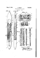
- Figure 1 is a plan view of a shuttle of the standard type embodying my improved lining
- Figure 2 is a side elevation of the shuttle with one side broken away to show the grooved lining in place inthe bobbin chamber;
- Figure 3 is a transverse section on an enlarged scale taken approximately on the line 3-3 of Figure 1;
- Figure 4 is a cross sectional view through the lining strip, showing the protective covering for the tacky adhesive coating partially removed;
- Figure 5 is a top plan of the grooved lining
- Figure 6 is a side elevation of the lining strip
- the numeral l designates a shuttle of the standard type, thesame being provided with the usual bobbin chamber 2 in which the bobbin 3 of yarnd is carried by the customary holder 5 in the rear end of the bobbin chamber. (The eye in the forward end of the shuttle through which the thread passes is indicated at 6. l
- My improvedlining comprises a pile fabric having a relatively thin, closely ⁇ woven fabric basel.
- a pile 8, formed preferably of mohair bers extends from the upper or front face of the base 1.
- the material undergoesa special treatment for cleaning the fibers of the pile and removing the oil therefrom.
- the pile fabric is placed in a fur cleaning machine or fur drum, together with a quantity of finely ground vegetable bers and the latter will remove practically all of the oils in the fibers ofthe pile fabric.
- the pile fabric will be rendered as'soft as possible and made more resilient, thus improving its qualities for use in the shuttle.
- the pile fabric which I use will simulate in density, bulk and softness, v'natural fur.
- the rear or back face of the cloth base is coated with rubber latex.
- This latex covering is denoted by the numeral 9.
- the latex coating will also secure the pile fibers in the base l.
- the longitudinal groove or recess l0 that extends through the center o1 the pile fabric for the full length of the lining strip.
- this groove extends from the outer face of the pile 8 to the base 1.
- the groove is of uniform width, although it is to be understood that the cross sectional shape of the groove may vary. Further, the groove may vary in width and depth depending upon the amount of tension that may be required.
- the groove may be formed by cutting through the central portion of the pile 8 With any suitable instrument or machine, or in the process of Weaving the pile fabric on the base. This groove is formed in the pile for the purpose of eliminating too much bulkiness in the bobbin chamber and at the same time will control the amount of tension applied against the yarn or filling on the bobbin.
- a tacky adhesive coating ll is applied to the desired to line a shuttle, the strip is -unwound .i
- the protective covering I2 is removed from the adhesive coating and the lining is inserted in the bobbin chamber and the adhesive coating is pressed against the side wall of the vbobbin chamber on each side, thereby aflixing the lining strips on the inner opposed faces of the side Walls of the bobbin chamber.
- the lining strips are positioned in the bobbin chamber before the -v bobbin and the yarn thereon are disposed longitudinally within the chamber.
- My improved lining may extend for the full length of the bobbin to prevent the yarn from ballooning and Aat the same time create a friction serving as a tension for the yarn as it is removed off of the bobbin.
- a lining of the above mentioned character can be manufactured and sold at a very low cost and due to its simplicity can be readily and easily installed and removed and replaced.
- a lining for the chamber comprising a .fabric base secured to each of the side walls of the bobbin chamber, and a pile carried by the base for contact with the yarn on the bobbin, said pile being provided with a central longitudinally extending groove to prevent bulkiness when the pile is -in Contact with the yarn.
- a lining for the chamber comprising a fabric base, a pile carried by the front face of the base for contact with the yarn on the bobbin, a rubber coating applied to the rear face of the base, a tacky adhesive coating on the rear face of the rubber coated base for securing the lining to each of the side walls of the bobbin chamber, said pile fabric being provided with a central longitudinally ⁇ extending groove that extends inwardly from the front side thereof, to prevent bulkiness when the pile is in engagement with the yarn on the bobbin.
- a lining for the chamber comprising a fabric base secured to each of the side walls of the bobbin chamber, and a pile carried by the base for Contact with the yarn on the bobbin, said pile being provided with a central recess that extends inwardly from the outer face thereof to the base for the full length of the lining to prevent bulkiness when the pile is in engagement with the yarn on the bobbin.
Landscapes
- Engineering & Computer Science (AREA)
- Textile Engineering (AREA)
- Woven Fabrics (AREA)
Description
March 7, 1944. s, GERsO-N' 2,343,659 l LINING FOR TEXTILE SHUTTLES Filed Dec. '7, 1942 I N VEN TOR.
Patented Mar. 7, 1944 OFFICE LINING Fon TEXTILE sHUrTLEs Seymour Gerson, Morristown, Tenn.
Application December 7, 1942, serial No. 468,131
3 Claims.
fabric, a groove being formed in the central portion of the pile so that when the lining is in placev in the bobbin chamber, the groove will eliminate too much bulkiness and the application of too much tension against the yarn or vlling.
A still further object of the invention is to provide a lining for textile shuttles wherein the relatively thin fabric base of the pile fabric has a tacky adhesive coating applied to its rear face, whereby the lining may be secured in place against the side walls of the bobbin chamber, a removable protective covering being associated with the tacky adhesive coating to permit handling of the lining prior to its use in the shuttle.
A further object is to provide a lining of the above mentioned character that may be manufactured in strip form of indeterminate length and wound on spools, so that any length of the strip lining may be unwound from the spool and cut to the desired size of the bobbin chamber.
Other objects and advantages will become apparent from the following description when taken in connection with the accompanying drawing.
In the accompanying drawing forming a part of this specification and wherein like reference characters designate corresponding parts throughout the several views:
Figure 1 is a plan view of a shuttle of the standard type embodying my improved lining;
Figure 2 is a side elevation of the shuttle with one side broken away to show the grooved lining in place inthe bobbin chamber;
Figure 3 is a transverse section on an enlarged scale taken approximately on the line 3-3 of Figure 1;
Figure 4 is a cross sectional view through the lining strip, showing the protective covering for the tacky adhesive coating partially removed;
Figure 5 is a top plan of the grooved lining;
Figure 6 is a side elevation of the lining strip, and
4, Figures 7 and 8 show different modifications of the lining. y
In the drawing, the numeral ldesignates a shuttle of the standard type, thesame being provided with the usual bobbin chamber 2 in which the bobbin 3 of yarnd is carried by the customary holder 5 in the rear end of the bobbin chamber. (The eye in the forward end of the shuttle through which the thread passes is indicated at 6. l
My improvedlining comprises a pile fabric having a relatively thin, closely `woven fabric basel. A pile 8, formed preferably of mohair bers extends from the upper or front face of the base 1.
After the pile has'been Woven onto the fabric base the material undergoesa special treatment for cleaning the fibers of the pile and removing the oil therefrom. To 'this end, the pile fabric is placed in a fur cleaning machine or fur drum, together with a quantity of finely ground vegetable bers and the latter will remove practically all of the oils in the fibers ofthe pile fabric.
In this manner, the pile fabric will be rendered as'soft as possible and made more resilient, thus improving its qualities for use in the shuttle. The pile fabric which I use will simulate in density, bulk and softness, v'natural fur.
For the purpose of rpreventing unraveling, 'the rear or back face of the cloth base is coated with rubber latex. This latex covering is denoted by the numeral 9. The latex coating will also secure the pile fibers in the base l.
One of the salient features of the instant invention is the provision of the longitudinal groove or recess l0 that extends through the center o1 the pile fabric for the full length of the lining strip. As is clearly shown in Figures 3 and 4, this groove extends from the outer face of the pile 8 to the base 1. In the preferred form, the groove is of uniform width, although it is to be understood that the cross sectional shape of the groove may vary. Further, the groove may vary in width and depth depending upon the amount of tension that may be required.
The groove may be formed by cutting through the central portion of the pile 8 With any suitable instrument or machine, or in the process of Weaving the pile fabric on the base. This groove is formed in the pile for the purpose of eliminating too much bulkiness in the bobbin chamber and at the same time will control the amount of tension applied against the yarn or filling on the bobbin.
A tacky adhesive coating ll is applied to the desired to line a shuttle, the strip is -unwound .i
from the spool Aand cut to the desired length.
The protective covering I2 is removed from the adhesive coating and the lining is inserted in the bobbin chamber and the adhesive coating is pressed against the side wall of the vbobbin chamber on each side, thereby aflixing the lining strips on the inner opposed faces of the side Walls of the bobbin chamber.
It is, of course, understood that the lining strips are positioned in the bobbin chamber before the -v bobbin and the yarn thereon are disposed longitudinally within the chamber.
While I have disclosed the lining as having a tacky adhesive applied to the back face of the base, it is to be understood that this adhesive coating may be left off and the lining secured in the bobbin chamber in any suitable manner.
When the filled bobbin is in its proper position in the chamber 2, the yarn 4 will press against the pile 8 in the manner as illustrated in Figure 3, forcing the fibers of the pile down toward the base "l, thus the groove Hl will function to prevent bulkiness, such as would occur if no groove was present.
My improved lining may extend for the full length of the bobbin to prevent the yarn from ballooning and Aat the same time create a friction serving as a tension for the yarn as it is removed off of the bobbin.
In Figures 7 and .8, modifications of the lining are shown, wherein the pile varies in height from one end of the strip to the other. In Figure 7 the pile fabric has the bers of its rear or ,lower end portion of one length, the intermediate group of fibers being longer and the top or forward group of ibers still longer. In .Figure 8, the fibers increase gradually .in'leng'th from the rear toward the` forward end of 'the strip.
A lining of the above mentioned character can be manufactured and sold at a very low cost and due to its simplicity can be readily and easily installed and removed and replaced.
While I have shown the preferred embodiment of my invention, it is to be understood that various changes in size, shape and arrangement of parts may be resorted to without departing from the spirit of the invention and the scope of the appended claims.
Having thus described the invention, what I claim is:
1. In combination with a shuttle having a bobbin chamber and a bobbin carrying yarn mounted therein; a lining for the chamber comprising a .fabric base secured to each of the side walls of the bobbin chamber, and a pile carried by the base for contact with the yarn on the bobbin, said pile being provided with a central longitudinally extending groove to prevent bulkiness when the pile is -in Contact with the yarn.
'2. In combination with a shuttle having a bobbin .chamber and a bobbin carrying yarn mounted therein; a lining for the chamber comprising a fabric base, a pile carried by the front face of the base for contact with the yarn on the bobbin, a rubber coating applied to the rear face of the base, a tacky adhesive coating on the rear face of the rubber coated base for securing the lining to each of the side walls of the bobbin chamber, said pile fabric being provided with a central longitudinally `extending groove that extends inwardly from the front side thereof, to prevent bulkiness when the pile is in engagement with the yarn on the bobbin.
v3. In combination with a shuttle having `a bobbin chamber and a bobbin carrying yarn mounted therein; a lining for the chamber comprising a fabric base secured to each of the side walls of the bobbin chamber, and a pile carried by the base for Contact with the yarn on the bobbin, said pile being provided with a central recess that extends inwardly from the outer face thereof to the base for the full length of the lining to prevent bulkiness when the pile is in engagement with the yarn on the bobbin.
SEYMOUR GERSON.
Priority Applications (1)
| Application Number | Priority Date | Filing Date | Title |
|---|---|---|---|
| US468131A US2343659A (en) | 1942-12-07 | 1942-12-07 | Lining for textile shuttles |
Applications Claiming Priority (1)
| Application Number | Priority Date | Filing Date | Title |
|---|---|---|---|
| US468131A US2343659A (en) | 1942-12-07 | 1942-12-07 | Lining for textile shuttles |
Publications (1)
| Publication Number | Publication Date |
|---|---|
| US2343659A true US2343659A (en) | 1944-03-07 |
Family
ID=23858550
Family Applications (1)
| Application Number | Title | Priority Date | Filing Date |
|---|---|---|---|
| US468131A Expired - Lifetime US2343659A (en) | 1942-12-07 | 1942-12-07 | Lining for textile shuttles |
Country Status (1)
| Country | Link |
|---|---|
| US (1) | US2343659A (en) |
Cited By (6)
| Publication number | Priority date | Publication date | Assignee | Title |
|---|---|---|---|---|
| US2667052A (en) * | 1949-06-02 | 1954-01-26 | Sarl So Called Lebocey Machine | Thread feeder for knitting and hosiery machines |
| US3187781A (en) * | 1963-06-28 | 1965-06-08 | Dorothy R Woodell | Yarn guiding and tensioning attachment for automatic loom shuttles having bobbins |
| US3194277A (en) * | 1961-10-19 | 1965-07-13 | Ralph Balut | Thread feed control for shuttles |
| US3261377A (en) * | 1963-03-22 | 1966-07-19 | Ralph Balut | Thread feed control for shuttles |
| US3882904A (en) * | 1973-08-16 | 1975-05-13 | Isidore Bergner | Shuttle fur |
| US4541350A (en) * | 1984-11-05 | 1985-09-17 | The Singer Company | Thread retaining cloth strip for lockstitch sewing machines |
-
1942
- 1942-12-07 US US468131A patent/US2343659A/en not_active Expired - Lifetime
Cited By (6)
| Publication number | Priority date | Publication date | Assignee | Title |
|---|---|---|---|---|
| US2667052A (en) * | 1949-06-02 | 1954-01-26 | Sarl So Called Lebocey Machine | Thread feeder for knitting and hosiery machines |
| US3194277A (en) * | 1961-10-19 | 1965-07-13 | Ralph Balut | Thread feed control for shuttles |
| US3261377A (en) * | 1963-03-22 | 1966-07-19 | Ralph Balut | Thread feed control for shuttles |
| US3187781A (en) * | 1963-06-28 | 1965-06-08 | Dorothy R Woodell | Yarn guiding and tensioning attachment for automatic loom shuttles having bobbins |
| US3882904A (en) * | 1973-08-16 | 1975-05-13 | Isidore Bergner | Shuttle fur |
| US4541350A (en) * | 1984-11-05 | 1985-09-17 | The Singer Company | Thread retaining cloth strip for lockstitch sewing machines |
Similar Documents
| Publication | Publication Date | Title |
|---|---|---|
| US2521055A (en) | Textile fabric | |
| US2343659A (en) | Lining for textile shuttles | |
| JP2618481B2 (en) | Coating device for applying paraffin oil to the surface of woven yarn | |
| US3089379A (en) | Apparatus for making braided cord | |
| US2486963A (en) | Method of making tufted terry products | |
| US2428101A (en) | Tight-grip temple roll | |
| US2031375A (en) | Noncreep elastic strands for elastic fabrics | |
| US2499406A (en) | Tufted terry product | |
| CN204898207U (en) | Sectional warper | |
| US2120910A (en) | Yarn package | |
| US1741351A (en) | Roll for textile machinery | |
| US2065072A (en) | Spool | |
| US2041418A (en) | Cellulose cord | |
| US3882904A (en) | Shuttle fur | |
| US2614587A (en) | Thread supporting means for shuttles | |
| US1585921A (en) | Shuttle | |
| US1687467A (en) | Automatically-threading loom shuttle | |
| US1273794A (en) | Shuttle. | |
| US2492670A (en) | Pile fabric | |
| US2310369A (en) | Shuttle box | |
| US3194277A (en) | Thread feed control for shuttles | |
| US2076424A (en) | Shuttle | |
| US2079535A (en) | Shuttle for looms | |
| US2305671A (en) | Loom temple roll | |
| US2110744A (en) | Shuttle |