US2340887A - Control mechanism for absorption refrigerating apparatus - Google Patents
Control mechanism for absorption refrigerating apparatus Download PDFInfo
- Publication number
- US2340887A US2340887A US369780A US36978040A US2340887A US 2340887 A US2340887 A US 2340887A US 369780 A US369780 A US 369780A US 36978040 A US36978040 A US 36978040A US 2340887 A US2340887 A US 2340887A
- Authority
- US
- United States
- Prior art keywords
- temperature
- cooling
- boiler
- absorber
- heating
- Prior art date
- Legal status (The legal status is an assumption and is not a legal conclusion. Google has not performed a legal analysis and makes no representation as to the accuracy of the status listed.)
- Expired - Lifetime
Links
Images
Classifications
-
- F—MECHANICAL ENGINEERING; LIGHTING; HEATING; WEAPONS; BLASTING
- F25—REFRIGERATION OR COOLING; COMBINED HEATING AND REFRIGERATION SYSTEMS; HEAT PUMP SYSTEMS; MANUFACTURE OR STORAGE OF ICE; LIQUEFACTION SOLIDIFICATION OF GASES
- F25B—REFRIGERATION MACHINES, PLANTS OR SYSTEMS; COMBINED HEATING AND REFRIGERATION SYSTEMS; HEAT PUMP SYSTEMS
- F25B49/00—Arrangement or mounting of control or safety devices
- F25B49/04—Arrangement or mounting of control or safety devices for sorption type machines, plants or systems
- F25B49/046—Operating intermittently
Definitions
- This invention relates to new and useful improvements in absorption refrigerating apparatus having one or more intermittently operating units and more particularly to a control device for regulating the heating and cooling of the boiler absorber of each unit.
- each unit has a boiler absorber containing solid absorbent material capable of absorbing a gaseous refrigerant during one period of the operation (absorbing) and of giving up such refrigerant during the other period (generating).
- the boiler absorber is heated by any suitable means to drive out the gaseous refrigerant therefrom and into the evaporator end ⁇ of the unit where it is desired to maintain the lowest or refrigerating temperature, while for the absorption period the boiler absorber is cooled to permit the return thereinto of the refrigerant evaporated in the evaporator to be absorbed by the solid absorbent material.
- the operation of the unit from one phase to the other is controlled automatically by a thermostat switch de vice in thermal contact with the boilerabsorber so that when the heat input to the boiler absorber for lthe generating period reaches a pre- V determined amount, the thermostat switch device automatically shuts olf the heat and simultaneously opens a valve to permit the 4circulation of a cooling medium to cool the boiler absorber for the absorption period.
- the thermostat switch closes the valve to stop the circulation of the cooling medium and actuates the heating means to repeat the cycle.
- the present invention provides an adjustable control device for selectively regulating the rate of heat input for the boiler absorber and the corresponding rate of cooling thereof to selectively vary the length of each complete cycle, thereby controlling the amount of refrigeration produced by the evaporator.
- the invention consists also in the provision of a thermostat switch responsive to the temperature in the region to be cooled for automatically controlling the rate of heat input to the boiler absorber during the normal operation of the unit.
- the invention consists further in absorption refrigerating apparatus of the intermittent type capable of operating under abnormal or extraorproduce considerably lower degrees of cooling than refrigerating apparatus of this type heretofore known.
- the invention consists also in the provision of means for increasing the eiciency of the primary condenser for the abnormal operating conditions of the refrigerating apparatus and for correspondingly increasing the eiilciency or cooling capacity of the cooling system.
- the invention consists further in absorption refrigerating apparatus of the intermittent type, wherein the rate of heat input for the generation phase and the corresponding rate of cooling for the absorption phase are automatically controlled by temperature conditions outside the region to be cooled.
- Fig. 1 is a diagrammatic view of a refrigerating apparatus having a single intermittently operating unit embodying a control device in accordance with my invention, certain parts of the ataipparatus being shown broken away and in sec-
- Fig. 2 is a time-temperature diagram of'the operating conditions in the boiler absorber and vevaporator of the unit shown in Fig. l.
- Fig. 3 is a diagrammatic view similar to Fig. 1 showing a modified form of the secondary cooling system.
- Fig. 4 is'a diagrammatic view of a refrigerating apparatus showing my invention applied to two intermittently and alternately operating
- Fig. 5 is a diagrammatic view similar to Fig. 4'
- thermostat arrangement for automatically controlling the operation of a single intermittent unit upon variations in temperature conditions outside the cabinet
- Fig. 8 is a comparative time-temperature chart of the operating conditions in the boiler absorber during the absorption period for two diierent dinary conditions of relatively short cycles to temperature conditions outside the refrigerator cabinet.
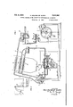
- the unit therein ⁇ illustrated comprises the usual boiler absorber Il having an annular compartment containing solid absorbent material Il, an inner annular cooling jacket I2, and a central vertical nue I3 in which is disposed an electric heating cartridge I4.
- the gaseous refrigerant is driven out of theboiler absorber I and passes upwardly through outlet conduit I5 into a condenser I6 arrangedin an air nue I1 where the refrigerant is condensed and flows through pipe I3 into an accumulator or collecting vessel I3 located in the upper portion of a refrigerator cabinet and preferably surrounded by insulating material 20.
- the liquid refrigerant flows through the evaporator 2l arranged adjacent the ice tray compartment of the refrigerator cabinet where it is desired to maintain the lowest temperature produced by evaporation of the refrigerant.
- the foregoing elements through which the gaseous refrigerant flows is generally known as the primary circulating system.
- the boiler absorber I0 is cooled by any suitable cooling device, that shown-in the drawings comprising a secondary cooling system formed with the annular cooling jacket I2 through which system a cooling medium circulates.
- the cooling fluid enters the bot- Atom of the jacket I2 through a conduit 22 leadvalve chamber 23.
- the lower end of switch lever 30 projects through a suitable opening in the bottom of the valve chamber sealed by a bellows diaphragm 32 and the free end of the switch lever carries an electrode 33 connected to one wire of a suitable, source of.
- switch lever 30 extends upwardly in the valve chamber 23 and is connected at its extreme upper end to a reciprocatable valve 36 which cooperates with a valve seat to control the circulation of the cooling medium through conduit 22.
- the switch lever 3l is suitably connected to a transverse rod 31 reciprocatable in the valve chamber 23 and normally urged to move in one direction by any suitable mechanism such, for example, as the coil spring 33 shown in the drawings whose loading pressure may be regulated by means of adjusting screw 35i. Movement of the rod 31 in the opposite direction is brought about by a bellows diaphragm 40 connected to the transverse rod 31 and responsive to a uid pressure system 4I in thermal contact with the boiler absorber III.
- the spring 36 urges rod 31 in a direction to normally maintain valve 36 closed upon its seat and the electrode 33 in engagement with the complementary electrode 34 so that circulation of the cooling medium through the secondary system is prevented while heat cartridge I4 is energized to heat the boiler absorber I0.
- the pressure developed in the fluid system 4I rises sufliciently to overcome the loading pressure of the spring 38 and move transverse rod 31 against the spring 33, thereby rocking switch lever 3B on its fulcrum 3l to move electrode 33 utz abutment 35 to de-energize heat cartridge I4 while simultaneously opening valve 36 to permit circulation of the cooling medium through the secondary system.
- the lower end of switch lever 36 is preferably connected to a snap spring device 42 to insure shifting of thel switch lever with a snap action, said spring yieldably maintaining the switch lever in either of its operating positions.
- the heat cartridge I4 is adapted toheat the boiler absorber I0 at different rates of heat input so that the length of each generating period may be correspondingly varied.
- a control device generally indicated as 43 having a hand-operated arm 44 rotatable about a central axis 45 and adapted to selectively engage l separate pairs of stationary contacts for diierent electrical circuits separately connected to the heat cartridge I4, whereby the latter may be energized to heat the boiler absorber III at dlilerent rates of heat input.
- the arm 44 of the control device 43 is adjustable from a position marked OIT when the unit is not ⁇ in operation, to four separate operating positions, marked 1, IL TIT and IV respectively.
- the heat cartridge I4 is energized to heat the boiler absorber Il at the minimum rate of heat input, namely, watts, so that the period of heating will be relatively long before the pressure in fluid pressure system 4I rises suiliciently to rock the switch lever 3l back to the position shown in Fig. 1 to open valve 36 and disengage electrode 33 from electrode 34 to interrupt the circuit through line 0.
- the cooling medium of the secondary cooling system flowing through jacket I2 will cool the boiler absorber Ill at the same rate as that of the heat input so that each complete cycle of operation of the unit, that is, generating period plus absorption period, will 'occur at regular but comparatively long intervals.
- the arm 44 is adjusted to position IL or position 111, depending upon temperature conditions outside the cabinet. In position IL one end lof the arm 44 closes the circuit between a pair ofcontacts a located on one side of the ⁇ control device 43, and the other end of the arm 44 closes another circuit between a second pair of contacts a' on the device 43 diametrically opposite contacts a.
- One of the contacts a is electrically connected to line
- lever 41 is operatively connected to a transverse rod 49 movable in one direction by means of a coil spring 50, the tension of which may be regulated by means of adjusting nut I. Movement of the rod 49 in the opposite direction is controlled by a bellows diaphragm 52 responsive to a fluid pressure system 53 arranged in the refrigerator cabinet.
- One of the contacts a is, electrically connected tothe opposite end of the mercury switch 46, while the other contact a is connected to line
- a third electrical connection is made from the centralportion of -the mercury switch 46 to the positive line of the current source.
- the heat cartridge I4 may be energized to heat the boiler absorber ⁇ I0 either at the rate of 120 watts, or at the rate of 160 watts, depending upon the position of the mercury switch 4B, to maintain a substantially uniform temperature inK the ⁇ refrigerator cabinet.
- the spring 50 will overcome the pressure in the fluid pressure system 53 and thegmercury switchr46 will be held in the position shown in Fig. 1.
- the heat cartridge I4 will therefore be energized to heat the boiler absorber I0 at the minimum rate of 120 watts by way of the circuit made by contacts a.
- the arm 44 is rotated on the control device 43 to position m where one end of said arm closes a circuit between a pair of contacts b, and the other end of the arm 44 closes the circuit besite contacts b on the control device 43.
- one ofcont'acts b is electrically connected to one end of the mercury switch 46 while one of the contacts b' is similarly u connected to the other end of the mercury switch.
- the other of contacts b is connected to line IBI and the other contact bf is connected to line 225 so that dependent upon the changes in temperature in the cabinet, as above pointed out for position 11, the boiler absorber I 0 will be heated either at the minimum rate of 1 60 watts, or at the maximum rate of 225 watts.
- the conventional secondary cooling system is usually suicient to take care of the three different rates of cooling required corresponding to the diierent rates of heat input.
- the length of eachy cycle must therefore be shortened, which means that the boiler absorber l'III must be heated lfor the generating period ata rapid rate and correspondingly cooled forv the absorbing period at the same rate.
- the capacity of the secondary cooling system must be increased over and above its natural cooling efliciency as otherwise the length of the absorbing period would not coincide with that of the generating period.
- the air cooled priinary'condenser IE might not be able to condense all ofthe refrigerant prior-.to being delivered to the evaporator 2
- the temperature in the evaporator 2l for this period is represented by solid line 51.
- an intermittent refrigerating unit capable of operating under variable conditions which may be regulated by simple hand adjustment of a control device to suit different temperature requirements in the refrigerator cabinet; also that for certain adjusted positions of the control device, the operating conditions of the refrigerating unit are automatically and selectively controlled by a thermostat-mercury switch arrangement to maintain a substantially uniform temperature in the cabinet.
- Fig. 3 is similar to that just described in connection with Fig. 1, with the exception that the secondary system includes in addition to the secondary double condenser 26 and collecting tank 28, an auxiliary double condenser Il, disposed in the lower portion of the flue I1 and connected to an auxiliary collecting tank 62 similar to collecting tank 28, by means of pipes 63.
- the cooling medium enters auxiliary con- -denser 6I by way of branch conduits 64 leading from the outlet Yconduit 24. From the auxiliary collecting tank 62- the cooling medium flows through conduit 65 to the valve chamber 2,3.
- the conduit 65 is provided with an electrically ope'rated valve generally indicated as 66 adapted to open when the arm 44 of control device 43 occupies position IV" to close the two pairs of contacts c and c'.
- valve 66 will remain closed so that only the cooling medium from collectingftank 26 will circulate through the secondary system to cool the boiler absorber I for each absorption period. However, when the unit ,is operating in position IV, valve 66 will open ⁇ to permit the cooling medium from auxiliary collecting tank 62 to supplement the amount of cooling medium in circulation during each absorption period to take care of the demand for rapid cooling.
- the apparatus illustrated consists of two intermittently and alternately operating units generally designated by. A and B, respectively, each similar to the unit heretofore described in connection with Figs. l and 3.
- unit A and B respectively, each similar to the unit heretofore described in connection with Figs. l and 3.
- the various parts of unit A have been designated by the same reference characters used in describing the previous iigures, while the corresponding parts of unit L have been indicated by theprime of the numeral.
- the switch lever -30 is movable in one direction by a bellows diaphragm 40 responsive to a fluid pressure system 4I in thermal contact with boiler absorber I0 of unit A, and is movable in the opposite direction by a similar bellows diaphragm 40' responsive to I a iiuid pressure system 4I in thermal contact with the boiler absorber I0 of unit B.
- the lower end of the switch lever 30 carries electrode members 33 and 33a, the former being connected to the negative of the source of current, as in Figs. 1 and 3, and the latter being connected to the positive of the source of current.
- Electrode 33 is adapted to alternately engage one and disengage the other of a pair of stationary electrodes 34 and 34 oppositely disposed on each side of the switch lever 30.
- Electrode 34 is electrically connected to the heat cartridge I4, while the other electrode 34 is similarly connected to the heat cartridge i4', so that when the switch lever 36 is rocked on its fulcrum 3i from one operatng position to the other, the movable electrode 33 will engage one of the stationary electrodes 34 or 34' to close the circuit to the corresponding heat cartridge and break the circuit to the other heat cartridge. Simultaneously with the making and breaking of these circuits, the double valve arrangement 36, 36' correspondingly closes one of the valves and opens the other.
- the movable electrode 33a cooperates with a second pair of stationary electrodes 61 and 61 also disposed on opposite sides of the switch lever 30 and electrically connected to separate contactmaking brushes 68 and 68 on the underside of one end of the rotatable arm 69 mounted on a control device 10 (Fig. 6).
- the opposite end of the arm 69 is also provided on its under side with separate contact-making brushes 1
- the aim 69 is rotatable about a central axis 12 and is adjustable from a position marked O11 on the control device 10, to four operating positions, 1, 11, "111 and ILIV'!!
- the control device 10 For positions 1, II and III of the arm 69, the control device 10 has an inner row d of three separate pairs of contacts adapted to be engaged selectively by the brush 68, and an outer concentrically arranged row e of three separate pairs of contacts adapted to be engaged by the brush 66.
- the control device For position IV, the control device has a single contact member 13 disposed radially inwardly of the inner row d and adapted to be engaged by a brush 14 mounted on the underside of the arm 69 adjacent the brush 68 as clearly shown in Fig. 6.
- the control device 10 is also provided with an inner row d of three separate pairs of contacts adapted to be engaged bythe brush 1I, and
- the mercury switch 43 automatically controls the rate of heat input tothe boiler absorbers I8 and I8' at either a minimum of 120 watts, or at a maximum of 160 watts.
- one of each of the contacts in the inner and outer rows d and e, respectively, is connected to one end olf the mercury switch 46, while the other of each of said pairs of contacts is connected to separate feed lines
- the mercury switch 48 will automatically regulate the rate of heating of the heat cartridges I4 and I4' betweenthe minimum of 120 watts and the maximum of 160 watts, de-
- the circuits to the heat cartridges I4 and I4 are made by way of the pairs of contacts in the inner and outer rows d and e', one contact of each of said pairs being connected to the corresponding feed lines 225 to the respective cartridges, and the other contact of each of said pairs being connected to the positive line of the current source.
- the units A and B ⁇ operate at abnormal conditions of relatively short cycles, one unit being heated at a rapid rate of heat input while the other unit simultaneously is being cooled at the corresponding rate.
- valve 38 is p shown arranged in the lower portion of the valve pending upon temperature conditions in the refrigerator cabinet.
- the mercury switch 46 is again operative to automatically control thel rate ofenergization of the heat cartridges I4 and I4' either at the minimum of 160 watts, or at the maximum of 225 watts, dependent upon the temperature variations in the cabinet.
- control arm 69 is shown occupying position IV with the contact 14 thereon engaging contact 'I3 on the control device Ill to close the circuit to the electric fan 54 as wel] as to the valve 66 so that in this operating position, the fan is continuously energized and valve chamber 23 and is operatively connected to the lower end of the switch lever 30 while the electrode member 33 is carried by the upper end of the lever instead of the arrangement shown in Fig. 1.
- vI provide separate transverse rods 82 and 83, one on each side of the switch lever 30, rod 82 being movable by the bellows diaphragm .48 responsive to the fluid pressure system 4I in thermal contact with the boiler absorber I0, and rod 83 being movable by a coil spring 84 interposed between the abutment 83a on the rod 83 and the diaphragm 80.
- will either move bellows diaphragm 88in onedirection to increase the loading pressure 'of spring 84,v or permit movement of the bellows diaphragm in the opposite direction to decrease the loading pressure of the spring.
- line 85 represents the temperature in the boiler absorber I 0 during the absorption period when lthe temperature outside the refrigerator cabinet isat a 'low before rocking switch lever 30 to start the generating period of the unit.
- Movement of the bellows diaphragm 80 from same is equally applicable to adsorption -refrigeronel position to the other can also be used to automatically regulate the rate of heat input to the boiler absorber by any suitable mechanism, such for example, as switch lever 90 iulcrumed as at 9i.
- One end of the lever 90 is provided with a pair of electrode members 92 and 93, the former being connected to one of the contacts a for position 11, for example, of (the control device 43, and the latter being connected to one of the contacts a.
- Electrode member 92 is adapted to cooperate for one position of the switch lever 90 with a complementary stationary electrode 94 connected to the feed line of the cartridge IB, and for the other position of the switch lever 90, electrode member cooperates with a complementary stationary electrode 95 connected to the feed line
- electrode 93 cooperates with a complementary stationary electrode 96 connected to feed line '
- the lower end of the switch lever 9B lies between spaced arms 91 carried by the bellows diaphragm of either 120 watts, or 16() Watts, dependent upon the position of the mercury switch d8 according to the temperature conditions in the cabinet.
- said refrigerating apparatus including 4a boiler-absorber, the combination with heating means for the generating period ci.' operation of said apparatus, cooling means for the absorption period of operation thereof, and thermostat mechanism responsive to the temperature in said boiler-absorber for selectively controlling said heating means and said cooling means to shift the operation of the apparatus from one period to the other; of a control devlce adjustable to diiierent positions for controlling the rate of heating of said heating means and the corresponding rate oi cooling of said cooling means, a thermostat device responsive to the temperature of said predetermined region for regulating the rate of heating of said heating means and the corresponding rate of cooling of said cooling means for certain positions of said control device, from a predetermined minimum -to a predetermined maximum, and a separate thermostat device responsive to the temperature outside said region, for automatically adjusting the rate of heating of said heating means and the corresponding rate of cooling of said cooling means from one position of said control device to another.
- absorption refrigerating apparatus of the intermittent type having two units operating in phase relation to one another to' produce substantially continuous refrigeration in a common cooling compartment, 'each unit having la"boi1e1 absorber, the combination of: heating means for. said boiler absorbers for the generating phase oration of each unit, cooling means for saidy boiler-absorbers for the absorption phase operaldifferent positions for controlling diierent rates of heating of said heating means and the corresponding diierent rates of cooling of said cooling means, a thermostat device responsive to the temperature in said boiler-absorbers for selectively controlling said heating means and said cooling means to shift the operation of the respective units from one phase to the other, and thermostat means responsive tothe temperature in said cooling compartment and operative for certain positions of said control device to regulate the rate of heat input to said boiler-absorbers between a .predetermined minimum and a predetermined maximum.
- each unit having a boiler-absorber adapted to be heated for the generating phase operation, and cooled for the absorption phase operation, and thermostat mechanism responsive to the temperature in said boiler-absorbers for shifting the operation of said units from one phase to the other to complete the cycle of operation of the respective units; the combination of a control device including means adjustable to different positions to regulate the rate of heat input and the corre ⁇ spending rate of coolingduring the generating and absorption phase operations, respectively, of each unit, and thermostat means responsive to the temperature in the space being cooled for regulating the heat input between a predetermined minimum and a predetermined maximum.
- absorption refrigerating apparatus of the intermittent ⁇ type including a boiler absorber, a condenser, and an evaporator, all coupled together to form a closed primary circulating system for a refrigerant, said boiler absorber containing absorbent material capable of absorbing refrigerant vapors during the absorption period and of giving up such refrigerant vapors during the generating period; means for heating said boiler absorber selectively at different rates of heat input, comprising anwelec- ,trical cartridge having separate feed lines of correspondingly different electrical values, means'adjustable to difierent'positions, certain of said positions closing two separate circuits throughV two of said feed lines, whereby. said heat cartridge may be energized at a predetermined maximum anda predetermined minimum,
- thermostat device responsive to the tempera-v ture adjacent said evaporator for selectively controlling said separate circuits for said certain positions of said adjustable means,.-and means connected to said feed line of highest value to perature in said combined generating and absorbing means fdr selectively controlling 'the heating and cooling of the latter; of adjustable means for controlling the rate of heating and the corresponding rate of cooling of said heating means and cooling means, respectively, said adjustable means including thermostat means responsive to the temperature in said space being cooled for regulating the rate of heating of said heating means between a predetermined minlmum and a predetermined maximum.
- absorption refrigerating-apparatus of the intermittent type operating to cool an enclosed space and including combined generating and absorbing means, heating means and cooling ⁇ means for said generating and absorbing means, and a thermostat mechanism responsive to the temperature in said combined generating and absorbing means for selectively controlling the heating and cooling of the latter; the combination of thermostat means responsive to the temperature in the space being cooled for regulaty ing the rate of heating of said heating means between a' variable minimum and a variable maximum, and separate thermostat means responsive to the temperature outside the space being cooled for determining the value of said y variable minimum and maximum rates regulated by said first named thermostat means.
- thermostat means responsive to the temperature in the space being cooled and operative for certain operating conditions determined by said adjusting means for regulating the rate of heating of said heating means between a predetermined minimum and a predetermined maximum.
- thermoelectricating apparatus including a plurality of units operating in phase relationship to produce substantially continuous refrigeration in an enclosed space, each unit having a boiler-absorber, the combination of heating means and cooling means for said boiler-absorbers, thermostat mechanism responsive to the temperature in means responsive to the temperature in said combined generating and absorbing means for selectively controlling the heating andy cooling of the latter, separate thermostat means responsive to the temperature in the space being cooled for regulating the rate of heat input to said combined generating and absorbing means, and an adjustable master control for regulating the rate -of heating of said heating means and the corresponding rate of cooling of said cooling means for controlling the operating conditions said boiler-absorbers for selectively controlling the heating and cooling of the latter to thereby control the operation of each unit from one phase to the other and vice versa, thermostat means responsive to the temperature in the space being cooled for regulating the rate of heating of said heating means between a predeterminedl minimum and a predetermined maximum, and meansfor varyingthe value of said predetermined minimum and pre
- intermittent absorption refrigerating apparatus operable to cool an enclosed space tively controlling the heating and cooling of the '4.5.
- thermostatmeans separate thermostat means responsive to the temperature in the space being cooled for regulating the rate of heat input to said combined generating and absorbing means, and means for adjusting the standard of regulation of said second named thermostatmeans.
- thermostat means responsive to the temperature in said combined generating and absorbing means for selectively controlling the heating and cooling of the latter, separate thermostat means responsive to the temperature in the space being cooled for regulating the rate of heat input to said combined generating and absorbing means, and an adjustable master control for said first named and second named thermostat means.
- intermittent absorption reirigerating apparatus operable to cool an enclosed space and having combined generating and absorbing means adapted to be heated during the generating periods and cooled during the absorbing periods of the apparatus, heating means and cooling means for said combined generating and absorbing means, the combination of thermostat of. said refrigerating apparatus.
- thermostat means responsive to the temperature in said combined generating and absorbing means for selectively controlling the heating and cooling of the latter
- separate thermostat means responsive to the temperature in the space being cooled for regulatng the rate of heat input to said combined generating and absorbing means
- thermostat means responsive to the temperature outside the space being cooled for automatically adjusting the standard of regulation of said second named thermostat means for a predetermined setting of said master control.
- thermocontrol including means responsive to the temperature in said boiler-absorber and operating to terminate the heating and initiate the cooling of said boiler-absorber at a predetermined temperature attained in the latter during the'generating period of the apparatus and to initiate the heating and terminate the cooling of said boiler-absorber at a predetermined minimum temperature attained in the 'latter during the absorbing period of the apparatus, and means responsive to the temperature outside the space being cooled for varying the operating standard of said first named temperature responsive means directly in accordance with ambient air temperature variations.
- thermoelectric heating means for said boiler-absorber
- control mechanism for said heating means including means responsive to the temperature in said boiler-absorber for terminating the heat supply at a predetermined temperature attained in said boiler-absorber during the generating phase operation of the refrigerating apparatus and for initiating the heat supply at a predetermined temperature attained in said boiler-absorber during the absorbing phase operation of the refrigerating apparatus, and means responsive to the temperature outside the space being cooled for varying the operating standard of said nrst named temperature responsive means directly in accordance with variations in ambient air temperature.
- heating means for said boiler-absorber including a boiler-absorber; the combination of heating means for said boiler-absorber, and control Amechanism for said heating means includingmeans responsive to the temperaturein said boiler-absorber for terminating the heat supply at a predetermined temperature attained in said boiler-absorber during the generating phase operation oi' the refrigerating apparatus and for initiating the heat supply at a predetermined.
- reirigerating apparatus of the intermittent absorption type operating to cool an enclosed space and including combined generating and absorbing means adapted to be heated during the generating periods and cooled during the absorbing periods of the reirigerating apparatus, and means for heating said combined generating and absorbing means intermittently: the combimcans at a predetermined temperature attainedn insaid combined generating and absorbing means during the cooling period, and means responsive to the temperature outside the space being cooled for varying the operating standard of said first named temperature responsive means in accordance with ambient air temperature variations.
- refrigerating apparatus of the intermit-l i tent absorption type operating to' cool a thermally insulated storage ⁇ space and including combined generating and absorbing means; the combination of heating means for said combined generating and absorbing means. and control mechanism including means controlling the operation of said heating means to heat said combined generating and absorbing means intermittently, means movable to a plurality of operating positions to adjust the rate of heating of said 'heating means for different operating conditions of theY refrigerating apparatus, and means responsive to the temperature in the space being cooled to increase and decrease the rate oi.' heat input to said com.- bined generating and absorbing means tor a predetermined setting of said second-named means.
Description
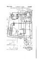
Feb. 8, 1944 N. ERLAND AF KLEEN CONTROL MECHANISM FOR ABSORPTION REFRIGERATING APPARATUS 5 Sheets-Sheet l Filed Dec. 12. 1940 Feb 8 1944 N. ERLAND AF KLEEN 2,340,837
CONTROL MECHANISM FOR ABSORPTION REFRIGERATING APPARATUS Filed Dec. 12, 1940 5 Sheets-Sheet 2 INVENTOR N/L` ERLAND AF KLEEN Feb- 8 1944' N. ERLAND AF KLEEN 2,340,887
CONTROL MECHANISM FOR ABSORPTION REFRIGERATING APPARATUS v Filed Dec. l2, 1940 5 Sheets-Sheet 3 INVENTOR N/LS ERLAND AF KLEE/V ATTO Feb. 8, 1944. N. ERLAND AF KLEEN CONTROL MECHANISM FOR ABSORPTION REFRIGERATING APPARATUS Filed Dec. 12, 1940 5 Sheets-Sheet 4 INVENTOR N/.L` ERLA/VD AF KLEE'N m. .Qi
Feb 8 1944- N. ERLAND AF KLEEN 2,340,387
CONTROL MECHANSM FOR ABSORPTION REFRIGERATING APPARATUS Patented Feb. 8, 194'? CONTROL DIECHANISM FR ABSORPTION REFRIGEBATING APPARATUS Nils Erland at Kleen, Stockholm, Sweden, assignor to Kleen Refrigerator, Inc., Hoboken, N. J., a corporation of Delaware Application DecemberI 12, 1940, Serial No. 369,780
22 Claims. v('Cl. 62-5) This invention relates to new and useful improvements in absorption refrigerating apparatus having one or more intermittently operating units and more particularly to a control device for regulating the heating and cooling of the boiler absorber of each unit.
In a refrigerating apparatus of this character, each unit has a boiler absorber containing solid absorbent material capable of absorbing a gaseous refrigerant during one period of the operation (absorbing) and of giving up such refrigerant during the other period (generating). For the generating period, the boiler absorber is heated by any suitable means to drive out the gaseous refrigerant therefrom and into the evaporator end `of the unit where it is desired to maintain the lowest or refrigerating temperature, while for the absorption period the boiler absorber is cooled to permit the return thereinto of the refrigerant evaporated in the evaporator to be absorbed by the solid absorbent material. The operation of the unit from one phase to the other is controlled automatically by a thermostat switch de vice in thermal contact with the boilerabsorber so that when the heat input to the boiler absorber for lthe generating period reaches a pre- V determined amount, the thermostat switch device automatically shuts olf the heat and simultaneously opens a valve to permit the 4circulation of a cooling medium to cool the boiler absorber for the absorption period. When the amount of cooling reaches a predetermined value, the thermostat switch closes the valve to stop the circulation of the cooling medium and actuates the heating means to repeat the cycle.
'I'he length of each complete cycle of operation of the unit, that is generating and absorption, is dependent upon the rate of heat input and the corresponding rate of cooling. The present invention provides an adjustable control device for selectively regulating the rate of heat input for the boiler absorber and the corresponding rate of cooling thereof to selectively vary the length of each complete cycle, thereby controlling the amount of refrigeration produced by the evaporator.
The invention consists also in the provision of a thermostat switch responsive to the temperature in the region to be cooled for automatically controlling the rate of heat input to the boiler absorber during the normal operation of the unit.
The invention consists further in absorption refrigerating apparatus of the intermittent type capable of operating under abnormal or extraorproduce considerably lower degrees of cooling than refrigerating apparatus of this type heretofore known.
The invention consists also in the provision of means for increasing the eiciency of the primary condenser for the abnormal operating conditions of the refrigerating apparatus and for correspondingly increasing the eiilciency or cooling capacity of the cooling system.
The invention consists further in absorption refrigerating apparatus of the intermittent type, wherein the rate of heat input for the generation phase and the corresponding rate of cooling for the absorption phase are automatically controlled by temperature conditions outside the region to be cooled.
The new and novel features of my invention will be hereinafter set forth-illustrated in the accompanying drawings, and more particularly pointed out in the appended claims.
Referring to the drawings in which numerals of like character designate similar parts throughout the several views,
Fig. 1 is a diagrammatic view of a refrigerating apparatus having a single intermittently operating unit embodying a control device in accordance with my invention, certain parts of the ataipparatus being shown broken away and in sec- Fig. 2 is a time-temperature diagram of'the operating conditions in the boiler absorber and vevaporator of the unit shown in Fig. l.
Fig. 3 is a diagrammatic view similar to Fig. 1 showing a modified form of the secondary cooling system.
Fig. 4 is'a diagrammatic view of a refrigerating apparatus showing my invention applied to two intermittently and alternately operating Fig. 5 is a diagrammatic view similar to Fig. 4'
' showing one form of thermostat arrangement for automatically controlling the operation of a single intermittent unit upon variations in temperature conditions outside the cabinet, and
Fig. 8 is a comparative time-temperature chart of the operating conditions in the boiler absorber during the absorption period for two diierent dinary conditions of relatively short cycles to temperature conditions outside the refrigerator cabinet.
In the drawings, referring more particularly to Fig. 1, the unit therein` illustrated comprises the usual boiler absorber Il having an annular compartment containing solid absorbent material Il, an inner annular cooling jacket I2, and a central vertical nue I3 in which is disposed an electric heating cartridge I4. During the generating period, the gaseous refrigerant is driven out of theboiler absorber I and passes upwardly through outlet conduit I5 into a condenser I6 arrangedin an air nue I1 where the refrigerant is condensed and flows through pipe I3 into an accumulator or collecting vessel I3 located in the upper portion of a refrigerator cabinet and preferably surrounded by insulating material 20. From the bottom of the accumulator I3 the liquid refrigerant flows through the evaporator 2l arranged adjacent the ice tray compartment of the refrigerator cabinet where it is desired to maintain the lowest temperature produced by evaporation of the refrigerant. The foregoing elements through which the gaseous refrigerant flows is generally known as the primary circulating system.
For the absorption period, the boiler absorber I0 is cooled by any suitable cooling device, that shown-in the drawings comprising a secondary cooling system formed with the annular cooling jacket I2 through which system a cooling medium circulates. The cooling fluid enters the bot- Atom of the jacket I2 through a conduit 22 leadvalve chamber 23. The lower end of switch lever 30 projects through a suitable opening in the bottom of the valve chamber sealed by a bellows diaphragm 32 and the free end of the switch lever carries an electrode 33 connected to one wire of a suitable, source of. electric current and adapted to cooperate on the one hand with a stationary electrode member 34 connected to the other wire of the source of electric current to energize the heat cartridge I4, and on the other hand, with an oppositely disposed abutment 35 sothat upon rocking of the switch lever .3l from one position to the other, the heat cartridge I4 will be intermittently energized and de-energized. The opposite end of switch lever 30 extends upwardly in the valve chamber 23 and is connected at its extreme upper end to a reciprocatable valve 36 which cooperates with a valve seat to control the circulation of the cooling medium through conduit 22.
Intermediate its extreme upper end and its fulcrum 3l, the switch lever 3l is suitably connected to a transverse rod 31 reciprocatable in the valve chamber 23 and normally urged to move in one direction by any suitable mechanism such, for example, as the coil spring 33 shown in the drawings whose loading pressure may be regulated by means of adjusting screw 35i. Movement of the rod 31 in the opposite direction is brought about by a bellows diaphragm 40 connected to the transverse rod 31 and responsive to a uid pressure system 4I in thermal contact with the boiler absorber III.
Thus the spring 36 urges rod 31 in a direction to normally maintain valve 36 closed upon its seat and the electrode 33 in engagement with the complementary electrode 34 so that circulation of the cooling medium through the secondary system is prevented while heat cartridge I4 is energized to heat the boiler absorber I0. When the amount of heat input reaches a predetermined point, the pressure developed in the fluid system 4I rises sufliciently to overcome the loading pressure of the spring 38 and move transverse rod 31 against the spring 33, thereby rocking switch lever 3B on its fulcrum 3l to move electrode 33 konto abutment 35 to de-energize heat cartridge I4 while simultaneously opening valve 36 to permit circulation of the cooling medium through the secondary system. The lower end of switch lever 36 is preferably connected to a snap spring device 42 to insure shifting of thel switch lever with a snap action, said spring yieldably maintaining the switch lever in either of its operating positions.
The heat cartridge I4 is adapted toheat the boiler absorber I0 at different rates of heat input so that the length of each generating period may be correspondingly varied. In accordance with the present invention, I have provided a control device generally indicated as 43 having a hand-operated arm 44 rotatable about a central axis 45 and adapted to selectively engage l separate pairs of stationary contacts for diierent electrical circuits separately connected to the heat cartridge I4, whereby the latter may be energized to heat the boiler absorber III at dlilerent rates of heat input. The arm 44 of the control device 43 is adjustable from a position marked OIT when the unit is not` in operation, to four separate operating positions, marked 1, IL TIT and IV respectively.
' In order to clarify the showing of the four different circiuts to the heat cartridge I4, the four feed lines thereto have been marked by the wattage value thereof, namely II, |20, |63 and 225. With the arm 44 of control device occupying the position I as shown in Fig. 1, after the boiler absorber I0 has been cooled and the pressure in the iuid pressure system 4I has dropped sulciently to permit the loading pressure of spring 33 to overcome the same and move transverse rod 31 to the left, switch lever 33 will be rocked on its fulcrum 3l to shift valve 36 on toits seat and correspondingly move electrode 33 into engagement with the stationary electrode 34. 'I'he circuit to the heat cartridge I4 is thus completed by way of the negative or minus line so marked in the drawing and above referred to as the feed line, and by way of the line ,designated. as |20 which passes through the pair of contacts for position I on the control switch 43 to the plus .or positive line of thev current source.
The heat cartridge I4 is energized to heat the boiler absorber Il at the minimum rate of heat input, namely, watts, so that the period of heating will be relatively long before the pressure in fluid pressure system 4I rises suiliciently to rock the switch lever 3l back to the position shown in Fig. 1 to open valve 36 and disengage electrode 33 from electrode 34 to interrupt the circuit through line 0. The cooling medium of the secondary cooling system flowing through jacket I2 will cool the boiler absorber Ill at the same rate as that of the heat input so that each complete cycle of operation of the unit, that is, generating period plus absorption period, will 'occur at regular but comparatively long intervals. It -will therefore be appreciated that the rate of refrigeration produced by evaporation of the refrigerant in the evaporator 2l will be quite slow and while possibly not enough to freeze water, it will be sulcient l,to keep a cool temperature in the refrigerator cabinet.
For the normal operation of the unit to produce a substantially uniformpredetermined low temperature in the cabinet. the arm 44 is adjusted to position IL or position 111, depending upon temperature conditions outside the cabinet. In position IL one end lof the arm 44 closes the circuit between a pair ofcontacts a located on one side of the` control device 43, and the other end of the arm 44 closes another circuit between a second pair of contacts a' on the device 43 diametrically opposite contacts a. One of the contacts a is electrically connected to line |20 and the other is in electrical connection with one side of a mercury switch '46 supported on the lower end of a rocking lever 41 fulcrumed as at 48. The upper end of lever 41 is operatively connected to a transverse rod 49 movable in one direction by means of a coil spring 50, the tension of which may be regulated by means of adjusting nut I. Movement of the rod 49 in the opposite direction is controlled by a bellows diaphragm 52 responsive to a fluid pressure system 53 arranged in the refrigerator cabinet.
One of the contacts a is, electrically connected tothe opposite end of the mercury switch 46, while the other contact a is connected to line |60. A third electrical connection is made from the centralportion of -the mercury switch 46 to the positive line of the current source.
In this position of the arm 44, the heat cartridge I4 may be energized to heat the boiler absorber` I0 either at the rate of 120 watts, or at the rate of 160 watts, depending upon the position of the mercury switch 4B, to maintain a substantially uniform temperature inK the` refrigerator cabinet. In other words, as long as the cabinet temperature remains at a predetermined minimum, the spring 50 will overcome the pressure in the fluid pressure system 53 and thegmercury switchr46 will be held in the position shown in Fig. 1. The heat cartridge I4 will therefore be energized to heat the boiler absorber I0 at the minimum rate of 120 watts by way of the circuit made by contacts a. However, should the tem.- perature rise in the cabinet dueto loading the cabinet or opening the door thereof, the pressure in pressure fluid system 53 will rise and operate bellowsl diaphragm 52 to move rod 49 against the loading pressure of spring 50 thereby rocking mercury switch 48 to its opposite position. The cartridge I4 will therefore be energized by way of contacts a' closing the circuit to the 160 watt line and the boiler absorber I0 heated more rapidly. As soon as the temperature drops toth predetermined minimum, the loading pressure of spring 50 will overcome the lowered pressure in the fluid pressure system 53 and rock mercury switch 45 back to the position shown in Fig. 1'so that heat cartridge will then be energized by the 120 watt line.
In order to maintain the predetermined normal temperature in the cabinet when the temperature outside the cabinet rises above a predetermined level, the arm 44 is rotated on the control device 43 to position m where one end of said arm closes a circuit between a pair of contacts b, and the other end of the arm 44 closes the circuit besite contacts b on the control device 43. As in the case of contacts a and a', one ofcont'acts b is electrically connected to one end of the mercury switch 46 while one of the contacts b' is similarly u connected to the other end of the mercury switch.
The other of contacts b is connected to line IBI and the other contact bf is connected to line 225 so that dependent upon the changes in temperature in the cabinet, as above pointed out for position 11, the boiler absorber I 0 will be heated either at the minimum rate of 1 60 watts, or at the maximum rate of 225 watts.
In the operation of the unit for the three positions of the control device just described, the conventional secondary cooling system is usually suicient to take care of the three different rates of cooling required corresponding to the diierent rates of heat input. However, in the event a sudden demand for refrigeration ris required in the cabinet, for instance, when it is desired to make ice in a relatively short time, the length of eachy cycle must therefore be shortened, which means that the boiler absorber l'III must be heated lfor the generating period ata rapid rate and correspondingly cooled forv the absorbing period at the same rate. In] this event, the capacity of the secondary cooling system must be increased over and above its natural cooling efliciency as otherwise the length of the absorbing period would not coincide with that of the generating period. Moreover, inasmuch as the refrigerant is expelled from the boiler absorber I0 at such an increased rate during the generating periods when the unit is operatingy under abnormal conditions, the air cooled priinary'condenser IE might not be able to condense all ofthe refrigerant prior-.to being delivered to the evaporator 2|, and in order to insure proper condensation of the refrigerant, means must be provided-for increasing the eiciency of this condenser.
In Fig. 1` I have shown one -arrangement to increase the normal cooling'eiilciency of the secondary cooling system as well as that of the con:
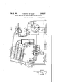
denser I6 by means of electric fan 54 which is continuously energized when the arm 44 occupies position IV and one end of the arm engages contacts c on the control device 43, one of which contacts leads from the. positive of 'the current source and the other leads --to the fan 54 connected to the negative of the current source. The other end of arm 44 closes contacts c', one of which leads to the line 225 and the 4 .In Fig. 2 lI have shown a` time-teniperaturev ,chart to illustrate'two complete cycles of the refrigerating unit described, solid line -55 representing the .temperature rise lin the boiler absorber I0 during the generating period for normal -operating conditions of the unit when the arm 44 is in positions IIv'or IIL while broken line 56 designates the corresponding temperature drop in the boiler absorber during the absorption tween a pair of contacts b' diametrically oppo- 7s period.
The temperature in the evaporator 2l for this period is represented by solid line 51.
When the arm 44 is moved to position'.IV, each cycle of the unit takes place in approximately one-half the time required for the II or III,positions. The temperature rise in the boiler absorber I0 for this abnormal operating condition of the unit is indicated Fig. 2 ,by
solid line 58 and the corresponding temperature drop therein during the absorption period is indicated by broken line 59; the evaporator temperature is indicated -by line 60 from which it will be observed that this temperature drops considerably lower than when the unit is operating in the II or III positions. 4
It will thus be seen from the foregoing description that I have provided an intermittent refrigerating unit capable of operating under variable conditions which may be regulated by simple hand adjustment of a control device to suit different temperature requirements in the refrigerator cabinet; also that for certain adjusted positions of the control device, the operating conditions of the refrigerating unit are automatically and selectively controlled by a thermostat-mercury switch arrangement to maintain a substantially uniform temperature in the cabinet.
It will also beobserved that for the normal operating conditions of the unit, the usual airv cooled secondary system is suiiicient to cool the boiler absorber for the various periods of absorption. However, for abnormal operating conditions of the unit when the boiler absorber is heated at a high rate, and consequently for shorter periods, the cooling capacity of the secondary system is increased to cool the boiler absorber in the relatively short time required for proper operation of the refrigerating unit.
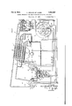
'I'he unit shown in Fig. 3 is similar to that just described in connection with Fig. 1, with the exception that the secondary system includes in addition to the secondary double condenser 26 and collecting tank 28, an auxiliary double condenser Il, disposed in the lower portion of the flue I1 and connected to an auxiliary collecting tank 62 similar to collecting tank 28, by means of pipes 63. The cooling medium enters auxiliary con- -denser 6I by way of branch conduits 64 leading from the outlet Yconduit 24. From the auxiliary collecting tank 62- the cooling medium flows through conduit 65 to the valve chamber 2,3. The conduit 65 is provided with an electrically ope'rated valve generally indicated as 66 adapted to open when the arm 44 of control device 43 occupies position IV" to close the two pairs of contacts c and c'.
Thus, during the normal operation of the unit,
or when the arm 44 is rotated to any of the positions I, 1I or 111, the valve 66 will remain closed so that only the cooling medium from collectingftank 26 will circulate through the secondary system to cool the boiler absorber I for each absorption period. However, when the unit ,is operating in position IV, valve 66 will open `to permit the cooling medium from auxiliary collecting tank 62 to supplement the amount of cooling medium in circulation during each absorption period to take care of the demand for rapid cooling.
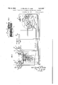
Referring to Fig. 4, the apparatus illustrated consists of two intermittently and alternately operating units generally designated by. A and B, respectively, each similar to the unit heretofore described in connection with Figs. l and 3. For convenience, the various parts of unit A have been designated by the same reference characters used in describing the previous iigures, while the corresponding parts of unit L have been indicated by theprime of the numeral.
The operation of units A and B from one phase to the other is automatically controlled by a thermostat switch similar to that shown in Figs.
1 and 3 with the exception that the switch lever double valve arrangement 36, 36 controlling the circulation in the secondary system to the respective boiler absorber jackets I2, I2'. The switch lever -30 is movable in one direction by a bellows diaphragm 40 responsive to a fluid pressure system 4I in thermal contact with boiler absorber I0 of unit A, and is movable in the opposite direction by a similar bellows diaphragm 40' responsive to I a iiuid pressure system 4I in thermal contact with the boiler absorber I0 of unit B.
The lower end of the switch lever 30 carries electrode members 33 and 33a, the former being connected to the negative of the source of current, as in Figs. 1 and 3, and the latter being connected to the positive of the source of current. Electrode 33 is adapted to alternately engage one and disengage the other of a pair of stationary electrodes 34 and 34 oppositely disposed on each side of the switch lever 30. Electrode 34 is electrically connected to the heat cartridge I4, while the other electrode 34 is similarly connected to the heat cartridge i4', so that when the switch lever 36 is rocked on its fulcrum 3i from one operatng position to the other, the movable electrode 33 will engage one of the stationary electrodes 34 or 34' to close the circuit to the corresponding heat cartridge and break the circuit to the other heat cartridge. Simultaneously with the making and breaking of these circuits, the double valve arrangement 36, 36' correspondingly closes one of the valves and opens the other.
The movable electrode 33a cooperates with a second pair of stationary electrodes 61 and 61 also disposed on opposite sides of the switch lever 30 and electrically connected to separate contactmaking brushes 68 and 68 on the underside of one end of the rotatable arm 69 mounted on a control device 10 (Fig. 6). The opposite end of the arm 69 is also provided on its under side with separate contact-making brushes 1|, 1I' which, together with the brushes 68, 68 are adapted to regulate the length of each cycle of operation of 'the two units A and B. The aim 69 is rotatable about a central axis 12 and is adjustable from a position marked O11 on the control device 10, to four operating positions, 1, 11, "111 and ILIV'!! For positions 1, II and III of the arm 69, the control device 10 has an inner row d of three separate pairs of contacts adapted to be engaged selectively by the brush 68, and an outer concentrically arranged row e of three separate pairs of contacts adapted to be engaged by the brush 66. For position IV, the control device has a single contact member 13 disposed radially inwardly of the inner row d and adapted to be engaged by a brush 14 mounted on the underside of the arm 69 adjacent the brush 68 as clearly shown in Fig. 6. Diametrically opposite the pairs of contacts for positions II and 1II," and diametrically opposite the contact 13 for position 1V, the control device 10 is also provided with an inner row d of three separate pairs of contacts adapted to be engaged bythe brush 1I, and
an outer row e of three separate pairs of con-1 switch lever 38 are in engagement with electrodes 34' and 81' andthe circuit to the heat cartridge I 4' is therefore completed through the pair of contacts in the inner row e to heat the boiler absorber III' at the rate of 120 watts for the generating period of unit B. During this period, the unit A is absorbing, valve 36 being open to permit circulation in the secondary cooling system through boiler absorber jacket I2 by way of pipe 22, outlet 24, branch 25, secondary condenser 28,
When the switch lever 38 is automatically shifted to its opposite position in the manner hereinabove explained, the operation of the units is reversed, unit A operating in the generating phase and unit B operating in the absorption phase. The circuit to the heat cartridge I4 is completed through the pair of contacts in the inner row d, and the electrodes 33 and 33a on switch lever 38 in engagement with the electrodes 34 and 31, respectively, to heat the boiler absorber I8 at the rate of 120 watts. l
When the control arm 69 is rotated to position 11, the mercury switch 43 automatically controls the rate of heat input tothe boiler absorbers I8 and I8' at either a minimum of 120 watts, or at a maximum of 160 watts. For this position, one of each of the contacts in the inner and outer rows d and e, respectively, is connected to one end olf the mercury switch 46, while the other of each of said pairs of contacts is connected to separate feed lines |28 leading to the.
corresponding heat cartridges I4 and I4'. One of each of the pair of contacts inthe inner and outer rows d' and e is connected to the opposite end of the mercury switch 46, while the other of each of said pairs is connected to the two feed lines |38 of the heat cartridges I4 and I4', respectively. The operation of the units'A and B in this position of the control arm 88,is
believed obvious without further explanation, it.
being understood that the mercury switch 48 will automatically regulate the rate of heating of the heat cartridges I4 and I4' betweenthe minimum of 120 watts and the maximum of 160 watts, de-
I8' during their respective'periods. The circuits to the heat cartridges I4 and I4 are made by way of the pairs of contacts in the inner and outer rows d and e', one contact of each of said pairs being connected to the corresponding feed lines 225 to the respective cartridges, and the other contact of each of said pairs being connected to the positive line of the current source. Thus, the units A and B` operate at abnormal conditions of relatively short cycles, one unit being heated at a rapid rate of heat input while the other unit simultaneously is being cooled at the corresponding rate.
While I have shown threaded .nut 38 in Figs. 1 and 3 for manually regulating the loading pressure of spring 38 for the vtransverse rod 31 to compensate for dierent room temperature condiing the various parts of the unit, the valve 38 is p shown arranged in the lower portion of the valve pending upon temperature conditions in the refrigerator cabinet.
For position HI on the control device 10, the mercury switch 46 is again operative to automatically control thel rate ofenergization of the heat cartridges I4 and I4' either at the minimum of 160 watts, or at the maximum of 225 watts, dependent upon the temperature variations in the cabinet. One of each of the pair i oi' contacts in both the inner andfouter rows d and e, is connected to one side of the mercury switch 45, While the other of each of said pairs is connected to separate feed lines to the heat cartridges I4 and I4', respectively.` One of each of the diametrically opposite pairs of contacts int-he inner and outer rows d and e', is connected to the other side of the mercury switch 48, and the other of each of said pairs of said contacts is connected to separate feed lines 225 to the corresponding heat cartridges.
Referring to Fig. 5, the control arm 69 is shown occupying position IV with the contact 14 thereon engaging contact 'I3 on the control device Ill to close the circuit to the electric fan 54 as wel] as to the valve 66 so that in this operating position, the fan is continuously energized and valve chamber 23 and is operatively connected to the lower end of the switch lever 30 while the electrode member 33 is carried by the upper end of the lever instead of the arrangement shown in Fig. 1. 31 operatively connected to the switch lever 38 to rock the latter on its fulcrum 3l from one operating position to the other, vI provide separate transverse rods 82 and 83, one on each side of the switch lever 30, rod 82 being movable by the bellows diaphragm .48 responsive to the fluid pressure system 4I in thermal contact with the boiler absorber I0, and rod 83 being movable by a coil spring 84 interposed between the abutment 83a on the rod 83 and the diaphragm 80. It will thus be seen that upon variations in room temperature, the iiuid pressure system 8| will either move bellows diaphragm 88in onedirection to increase the loading pressure 'of spring 84,v or permit movement of the bellows diaphragm in the opposite direction to decrease the loading pressure of the spring.
Referring to the chart shown in Fig. 8, line 85 represents the temperature in the boiler absorber I 0 during the absorption period when lthe temperature outside the refrigerator cabinet isat a 'low before rocking switch lever 30 to start the generating period of the unit.
When the temperature outside the cabinet rises to the level indicated byline 81 in Fig. 8, the fluid 66 is held in open position to permit the cooling 4 iluid from auxiliary tank 62 to circulate with that vfrom tank 28 to cool the boiler absorbers I0 and pressure system 8i will move -bellows diaphragm `BI'I to the position indicated by dotted lines in Fig.
It will be seen from the foregoing that I have I provided a refrigerating apparatus having a sin- However, in place of the transverse rod gle intermittent unit whose operation from one phase to the other is automatically controlled by a thermostat switch that is in turn automatically adjusted according to room temperatures.
Movement of the bellows diaphragm 80 from same is equally applicable to adsorption -refrigeronel position to the other can also be used to automatically regulate the rate of heat input to the boiler absorber by any suitable mechanism, such for example, as switch lever 90 iulcrumed as at 9i. One end of the lever 90 is provided with a pair of electrode members 92 and 93, the former being connected to one of the contacts a for position 11, for example, of (the control device 43, and the latter being connected to one of the contacts a. Electrode member 92 is adapted to cooperate for one position of the switch lever 90 with a complementary stationary electrode 94 connected to the feed line of the cartridge IB, and for the other position of the switch lever 90, electrode member cooperates with a complementary stationary electrode 95 connected to the feed line |60 of the cartridge. 4
Similarly, for one position of the switch lever 91|, electrode 93 cooperates with a complementary stationary electrode 96 connected to feed line '|60 of the heatcartridge, and for the other position of the switch lever, electrode 93 cooperates with a complementary stationary electrode 91 connected tofeed line 225 of the cartridge. The lower end of the switch lever 9B lies between spaced arms 91 carried by the bellows diaphragm of either 120 watts, or 16() Watts, dependent upon the position of the mercury switch d8 according to the temperature conditions in the cabinet. However, should the temperature outside the cabinet rise to the point where bellows diaphragm 80 is moved to the dotted line position, thereby v rocking lever 9G on its fulcrum si to the opposite position, electrodes S2 and 93 will then engagev complementary electrodes 95 and el, respectively,vand the heat cartridge I4 will then be energized at the rate of either 160 watts, or 225 watts, depending upon the temperature conditions in the cabinet.
Thus, with the use of this auxiliary control arrangement, the rate of heating of the boiler absorber for a given position of the control device '43, is automatically adjusted to a different position of the control device without' manual ad- :lustrnent of the arm 44. It will be understood that while I have shown and described this auxiliary control in connection with a single unit, the same is equally applicable to the double unit shown in Fig. 4. f
Although I have shown the boiler' absorber of each unit heated by electrical means, the' same may be heated by any other means such, for example, as gas burners and the lik', in which event the control device-43 will operate different gas jets to regulate the rate of heat input. Furtherating systems and it will be understood therefore that the use of the term absorption in the specication as well as in the claims, is intended to instruction, operation and advantages of my inmore, instead of being operable only when the control armilld occupies position IV on the ycontrol device 33, the circuit to the fan 54 may be so arranged that said fan will be energized Whenever the boiler absorber it is heated at the rate of 225 watts.
While I have described the invention in connection with absorption refrigerating apparatus, the
vention may be readily understood by `those skilled in the art without further description, it being borne in mind that numerous changes may be made in thedetails disclosed without departing. from the spirit of the invention as set out in the following claims.
What I claim and desire to secure by Letters Patent is:
1. In absorption refrigerating apparatus of the intermittent type producing low temperature at a predetermined region, said refrigerating apparatus including 4a boiler-absorber, the combination with heating means for the generating period ci.' operation of said apparatus, cooling means for the absorption period of operation thereof, and thermostat mechanism responsive to the temperature in said boiler-absorber for selectively controlling said heating means and said cooling means to shift the operation of the apparatus from one period to the other; of a control devlce adjustable to diiierent positions for controlling the rate of heating of said heating means and the corresponding rate oi cooling of said cooling means, a thermostat device responsive to the temperature of said predetermined region for regulating the rate of heating of said heating means and the corresponding rate of cooling of said cooling means for certain positions of said control device, from a predetermined minimum -to a predetermined maximum, and a separate thermostat device responsive to the temperature outside said region, for automatically adjusting the rate of heating of said heating means and the corresponding rate of cooling of said cooling means from one position of said control device to another.
2. In intermittent absorption reirigerating apparatus having combined generating and absorbing means and operating to cool a compartment, the combination with heating means for said combined generating and absorbing means, cooling means for said combined generating and absorbing means, and thermostat mechanism for controlling said heating means and said cooling means; oi a control, device adjustable to different positions for controlling the rate of heating of said heating means and the corresponding rate of cooling of said cooling means, means responsive to the temperature in the compartment being cooled i'orr regulating the rate of heating of said heating means between a predetermined minimum and a predetermined maximum for certain positions of said control device, and means responsive to the temperature outside the said compartment for varying the rate of heating of said heating means from ,that corresponding to one position of said control device to that correspending to another position of said control device independently of the latter.
3. In absorption refrigerating apparatus of the intermittent type having two units operating in phase relation to one another to' produce substantially continuous refrigeration in a common cooling compartment, 'each unit having la"boi1e1 absorber, the combination of: heating means for. said boiler absorbers for the generating phase oration of each unit, cooling means for saidy boiler-absorbers for the absorption phase operaldifferent positions for controlling diierent rates of heating of said heating means and the corresponding diierent rates of cooling of said cooling means, a thermostat device responsive to the temperature in said boiler-absorbers for selectively controlling said heating means and said cooling means to shift the operation of the respective units from one phase to the other, and thermostat means responsive tothe temperature in said cooling compartment and operative for certain positions of said control device to regulate the rate of heat input to said boiler-absorbers between a .predetermined minimum and a predetermined maximum.
4. Inabsorption refrigerating apparatus of the intermittent type having two units operating in phase relationship to produce substantially continuous refrigeration in an enclosed space, each unit having a boiler-absorber adapted to be heated for the generating phase operation, and cooled for the absorption phase operation, and thermostat mechanism responsive to the temperature in said boiler-absorbers for shifting the operation of said units from one phase to the other to complete the cycle of operation of the respective units; the combination of a control device including means adjustable to different positions to regulate the rate of heat input and the corre` spending rate of coolingduring the generating and absorption phase operations, respectively, of each unit, and thermostat means responsive to the temperature in the space being cooled for regulating the heat input between a predetermined minimum and a predetermined maximum.
5. In absorption refrigerating apparatus of the intermittent `type including a boiler absorber, a condenser, and an evaporator, all coupled together to form a closed primary circulating system for a refrigerant, said boiler absorber containing absorbent material capable of absorbing refrigerant vapors during the absorption period and of giving up such refrigerant vapors during the generating period; means for heating said boiler absorber selectively at different rates of heat input, comprising anwelec- ,trical cartridge having separate feed lines of correspondingly different electrical values, means'adjustable to difierent'positions, certain of said positions closing two separate circuits throughV two of said feed lines, whereby. said heat cartridge may be energized at a predetermined maximum anda predetermined minimum,
a thermostat device responsive to the tempera-v ture adjacent said evaporator for selectively controlling said separate circuits for said certain positions of said adjustable means,.-and means connected to said feed line of highest value to perature in said combined generating and absorbing means fdr selectively controlling 'the heating and cooling of the latter; of adjustable means for controlling the rate of heating and the corresponding rate of cooling of said heating means and cooling means, respectively, said adjustable means including thermostat means responsive to the temperature in said space being cooled for regulating the rate of heating of said heating means between a predetermined minlmum and a predetermined maximum.
7. ,In refrigerating apparatus of the intermittent absorption type operating to cool an enclosed space and including combined generating and absorbing means, the combination with heating means and cooling means for said combined generating and absorbing means, and thermostat mechanism responsive to the temperature in said combined generating and absorbing means for selectively controlling the heating andcooling of the latter; of an adjustable control device for adjusting the rate of heating and the corresponding rate of cooling of said heating means and cooling means, respectively, for different operating conditions, and thermostat means responsive to the temperature in said space being cooled for regulating the rate of heating of said heating means between a predetermined minimum anda predetermined maximum for certain operating conditions determined bysaid adjustable control device.
8. In refrigerating apparatus of the intermittent absorption type operating to cool an enclosed space and including combined generating and absorbing means, the combination with heating means and cooling means for said combined generating and absorbing means, and thermostat mechanism responsivev to the temperature in said combined generating and absorbing means for selectively controlling the heating and cooling of the latter; of an adiustmotlcally varying the value vof said predetermined minimum and predetermined maximum.
9. In absorption refrigerating-apparatus of the intermittent type operating to cool an enclosed space and including combined generating and absorbing means, heating means and cooling` means for said generating and absorbing means, and a thermostat mechanism responsive to the temperature in said combined generating and absorbing means for selectively controlling the heating and cooling of the latter; the combination of thermostat means responsive to the temperature in the space being cooled for regulaty ing the rate of heating of said heating means between a' variable minimum and a variable maximum, and separate thermostat means responsive to the temperature outside the space being cooled for determining the value of said y variable minimum and maximum rates regulated by said first named thermostat means.
10. In absorption refrigerating apparatus, in
. combinatiomfa plurality of intermittent units operating in phase relationship for producing substantially continuous refrigeration in an enclosed space, each unit having a boiler-absorber, heating means and cooling means for' said boiler-absorbers. a thermostat .control responsivetothe temperature in said boiler-absorbers for selectively controlling the heating and cooling thereof to thereby control the operation oi each unit from one phase to the other and vice versa,
means for adjusting the rate of heating of said heating means and the corresponding rate of cooling of said cooling means for diierent operating Conditions of said units, and thermostat means responsive to the temperature in the space being cooled and operative for certain operating conditions determined by said adjusting means for regulating the rate of heating of said heating means between a predetermined minimum and a predetermined maximum.
ll. In rei'rigerating apparatus of the intermittent absorption type including a plurality of units operating in phase relationship to produce substantially continuous refrigeration in an enclosed space, each unit having a boiler-absorber, the combination of heating means and cooling means for said boiler-absorbers, thermostat mechanism responsive to the temperature in means responsive to the temperature in said combined generating and absorbing means for selectively controlling the heating andy cooling of the latter, separate thermostat means responsive to the temperature in the space being cooled for regulating the rate of heat input to said combined generating and absorbing means, and an adjustable master control for regulating the rate -of heating of said heating means and the corresponding rate of cooling of said cooling means for controlling the operating conditions said boiler-absorbers for selectively controlling the heating and cooling of the latter to thereby control the operation of each unit from one phase to the other and vice versa, thermostat means responsive to the temperature in the space being cooled for regulating the rate of heating of said heating means between a predeterminedl minimum and a predetermined maximum, and meansfor varyingthe value of said predetermined minimum and predetermined maximum rates regulated by said thermostat means.
12. In intermittent absorption refrigerating apparatus operable to cool an enclosed space tively controlling the heating and cooling of the '4.5.
latter, separate thermostat means responsive to the temperature in the space being cooled for regulating the rate of heat input to said combined generating and absorbing means, and means for adjusting the standard of regulation of said second named thermostatmeans.
13. In intermittent absorption refrigerating apparatus operable to cool an enclosed space and having combined generating and absorbing means adapted to be heated during the generating periods and cooled during the absorbing periods of the apparatus, heating means and cooling means for said combined generating and absorbing means, the combination of thermostat means responsive to the temperature in said combined generating and absorbing means for selectively controlling the heating and cooling of the latter, separate thermostat means responsive to the temperature in the space being cooled for regulating the rate of heat input to said combined generating and absorbing means, and an adjustable master control for said first named and second named thermostat means.
14. In intermittent absorption reirigerating apparatus operable to cool an enclosed space and having combined generating and absorbing means adapted to be heated during the generating periods and cooled during the absorbing periods of the apparatus, heating means and cooling means for said combined generating and absorbing means, the combination of thermostat of. said refrigerating apparatus.
15. In intermittent absorption refrigerating apparatus operable to cool an enclosed space and having combined generating and absorbing means adapted to be heated during the generating periods and cooled during the absorbing periods of the apparatus, heating means and cooling means for said combined generating and absorbing means, the combination of thermostat means responsive to the temperature in said combined generating and absorbing means for selectively controlling the heating and cooling of the latter, separate thermostat means responsive to the temperature in the space being cooled for regulatng the rate of heat input to said combined generating and absorbing means, 'an adjustable master control for regulating the rate of heating of said/heating means and the corresponding rate of cooling of said cooling means for controlling the operating conditions of said refrigerating apparatus, and thermostat means responsive to the temperature outside the space being cooled for automatically adjusting the standard of regulation of said second named thermostat means for a predetermined setting of said master control.
16. In refrigerating apparatus of the intermittent absorption type operating to cool an enclosed space and including a boiler-absorber adapted to be heated during the generating periods and cooled during the absorbing periods of the refrigerating apparatus; the combination of a thermostat control including means responsive to the temperature in said boiler-absorber and operating to terminate the heating and initiate the cooling of said boiler-absorber at a predetermined temperature attained in the latter during the'generating period of the apparatus and to initiate the heating and terminate the cooling of said boiler-absorber at a predetermined minimum temperature attained in the 'latter during the absorbing period of the apparatus, and means responsive to the temperature outside the space being cooled for varying the operating standard of said first named temperature responsive means directly in accordance with ambient air temperature variations. s
17. In refrigerating apparatus of the intermittent absorption type operating to cool an enclosed space and including a boiler-absorber; ther-,ombination of heating means for said boiler-absorber, and control mechanism for said heating means including means responsive to the temperature in said boiler-absorber for terminating the heat supply at a predetermined temperature attained in said boiler-absorber during the generating phase operation of the refrigerating apparatus and for initiating the heat supply at a predetermined temperature attained in said boiler-absorber during the absorbing phase operation of the refrigerating apparatus, and means responsive to the temperature outside the space being cooled for varying the operating standard of said nrst named temperature responsive means directly in accordance with variations in ambient air temperature.
18. In reirigerating apparatus of the intermittent absorption type operating to cool an enclosed space and including a boiler-absorber; the combination of heating means for said boiler-absorber, and control Amechanism for said heating means includingmeans responsive to the temperaturein said boiler-absorber for terminating the heat supply at a predetermined temperature attained in said boiler-absorber during the generating phase operation oi' the refrigerating apparatus and for initiating the heat supply at a predetermined. temperature attained in said boiler-absorber during the absorbing phase operation of the Vreirigerating apparatus, means responsive to lthe temperature outside the space being cooled for varying the operating standard of said first named temperature responsive means directly in accordance with variations in ambient in said boiler-absorber during the heating period and to terminate the cooling at a predetermined temperature attained in said boiler-absorber during the cooling period, and means responsive to the temperature outside the Yspace being cooled for varying the operating standard of said nrst named temperature responsive means directly' in accordance with variations in ,ambient air tenu,
perature.
20. In reirigerating apparatus of the intermittent absorption type operating to cool an enclosed space and including combined generating and absorbing means adapted to be heated during the generating periods and cooled during the absorbing periods of the reirigerating apparatus, and means for heating said combined generating and absorbing means intermittently: the combimcans at a predetermined temperature attainedn insaid combined generating and absorbing means during the cooling period, and means responsive to the temperature outside the space being cooled for varying the operating standard of said first named temperature responsive means in accordance with ambient air temperature variations.
21.1111 refrigerating apparatus of the intermittent absorption type operating to coci an enclosed space and including combined generating and absorbing means adapted to be heated during the generating periods and cooled during the absorbing periods of the refrigerating apparatus; the combination of heating means and cooling means for said combined' generating and absorbing means, and a control mechanism including pressure operated control means for said heating means and cooling means, a pressure creating fluid system responsive to the temperature in said combined generating and absorbing means and operating at a predetermined temperature attained in the latter during the generating pe# riod to move said control means in one direction to render said heating means ineffective to supply heat and simultaneously to render said cooling means eiective to cool said combined generating and absorbing means, a spring loading device to mcve said control means in the opposite direction against the pressure of said pressure creating iluid system and operating at a predetermined Y pressureattained in said pressure creating iiuid nation of an air cooled heat transfer system formed by a plurality of interconnected elements for the circulation or the heat transferring iiuid in heat exchange relation with said combinedV generating and absorbing means to cool the latter, valvemeans controlling the iiow or the heat transferring" :duid in said system, means responsive to the temperature in said combined 'generating and absorbing means to open saidV valve means at a predetermined temperature attained in said combined generating and absorbing means duringtheheatingperiodandtoclesaidvalve.
system corresponding to a predetermined" temperature attained in vsaid combined vgenerating and absorbing means during the absorbing period to render said cooling means ineffective to cool `and simultaneously to render said heating means etrective to heat said combined generating and absorbing means, and means responsive to the temperature outside the space being cooled for varying the loading pressure of said spring loading deviceagainstLsaid pressure creating fluid system directly in accordance with variations in ambient, air temperature.
22. In refrigerating apparatus of the intermit-l i tent absorption type operating to' cool a thermally insulated storage` space and including combined generating and absorbing means; the combination of heating means for said combined generating and absorbing means. and control mechanism including means controlling the operation of said heating means to heat said combined generating and absorbing means intermittently, means movable to a plurality of operating positions to adjust the rate of heating of said 'heating means for different operating conditions of theY refrigerating apparatus, and means responsive to the temperature in the space being cooled to increase and decrease the rate oi.' heat input to said com.- bined generating and absorbing means tor a predetermined setting of said second-named means.
NILSERLANDAIKIEEN.
Priority Applications (2)
| Application Number | Priority Date | Filing Date | Title |
|---|---|---|---|
| US369780A US2340887A (en) | 1940-12-12 | 1940-12-12 | Control mechanism for absorption refrigerating apparatus |
| GB16160/41A GB549730A (en) | 1940-12-12 | 1941-12-15 | Control mechanism for absorption refrigerating apparatus |
Applications Claiming Priority (1)
| Application Number | Priority Date | Filing Date | Title |
|---|---|---|---|
| US369780A US2340887A (en) | 1940-12-12 | 1940-12-12 | Control mechanism for absorption refrigerating apparatus |
Publications (1)
| Publication Number | Publication Date |
|---|---|
| US2340887A true US2340887A (en) | 1944-02-08 |
Family
ID=23456880
Family Applications (1)
| Application Number | Title | Priority Date | Filing Date |
|---|---|---|---|
| US369780A Expired - Lifetime US2340887A (en) | 1940-12-12 | 1940-12-12 | Control mechanism for absorption refrigerating apparatus |
Country Status (2)
| Country | Link |
|---|---|
| US (1) | US2340887A (en) |
| GB (1) | GB549730A (en) |
Cited By (7)
| Publication number | Priority date | Publication date | Assignee | Title |
|---|---|---|---|---|
| US5335519A (en) * | 1991-07-26 | 1994-08-09 | Societe Nationale Elf Aquitaine | Plant for producing cold by solid/gas reaction, reactor comprising means of cooling |
| US5477706A (en) * | 1991-11-19 | 1995-12-26 | Rocky Research | Heat transfer apparatus and methods for solid-vapor sorption systems |
| WO1996011368A1 (en) * | 1994-10-06 | 1996-04-18 | Electrolux Leisure Appliances Ab | Cooling device with intermittently operating cooling unit |
| US5598721A (en) * | 1989-03-08 | 1997-02-04 | Rocky Research | Heating and air conditioning systems incorporating solid-vapor sorption reactors capable of high reaction rates |
| US5628205A (en) * | 1989-03-08 | 1997-05-13 | Rocky Research | Refrigerators/freezers incorporating solid-vapor sorption reactors capable of high reaction rates |
| US5732569A (en) * | 1993-11-29 | 1998-03-31 | Mayekawa Mfg. Co., Ltd. | Adsorption type cooling apparatus, method of controlling cold output of same, and fin type adsorbent heat exchanger for use in the same |
| EP1645820A1 (en) * | 2004-10-08 | 2006-04-12 | Viessmann Werke GmbH & Co KG | Method of control for a periodically operating vacuum sorption device |
Families Citing this family (3)
| Publication number | Priority date | Publication date | Assignee | Title |
|---|---|---|---|---|
| GB2114816B (en) * | 1982-02-05 | 1985-11-20 | Ranco Inc | Temperature responsive control units |
| IT207788Z2 (en) * | 1986-04-04 | 1988-02-15 | Eltek Spa | WATER DIVERTER ASSEMBLY ASSOCIATED WITH ELECTRONIC PROGRAMMERS, PARTICULARLY FOR WASHING MACHINES |
| FR2749377B1 (en) * | 1996-05-30 | 1998-07-10 | Elf Aquitaine | METHOD FOR MANAGING A THERMOCHEMICAL REACTION OR SOLID-GAS ADSORPTION |
-
1940
- 1940-12-12 US US369780A patent/US2340887A/en not_active Expired - Lifetime
-
1941
- 1941-12-15 GB GB16160/41A patent/GB549730A/en not_active Expired
Cited By (9)
| Publication number | Priority date | Publication date | Assignee | Title |
|---|---|---|---|---|
| US5598721A (en) * | 1989-03-08 | 1997-02-04 | Rocky Research | Heating and air conditioning systems incorporating solid-vapor sorption reactors capable of high reaction rates |
| US5628205A (en) * | 1989-03-08 | 1997-05-13 | Rocky Research | Refrigerators/freezers incorporating solid-vapor sorption reactors capable of high reaction rates |
| US5335519A (en) * | 1991-07-26 | 1994-08-09 | Societe Nationale Elf Aquitaine | Plant for producing cold by solid/gas reaction, reactor comprising means of cooling |
| US5477706A (en) * | 1991-11-19 | 1995-12-26 | Rocky Research | Heat transfer apparatus and methods for solid-vapor sorption systems |
| US5732569A (en) * | 1993-11-29 | 1998-03-31 | Mayekawa Mfg. Co., Ltd. | Adsorption type cooling apparatus, method of controlling cold output of same, and fin type adsorbent heat exchanger for use in the same |
| US6041617A (en) * | 1993-11-29 | 2000-03-28 | Mayekawa Mfg. Co., Ltd. | Adsorption type cooling apparatus, method of controlling cold output of same, and fin type adsorbent heat exchanger for use in same |
| WO1996011368A1 (en) * | 1994-10-06 | 1996-04-18 | Electrolux Leisure Appliances Ab | Cooling device with intermittently operating cooling unit |
| US5881573A (en) * | 1994-10-06 | 1999-03-16 | Electrolux Leisure Appliances Ab | Refrigerating device with cooling unit working intermittently |
| EP1645820A1 (en) * | 2004-10-08 | 2006-04-12 | Viessmann Werke GmbH & Co KG | Method of control for a periodically operating vacuum sorption device |
Also Published As
| Publication number | Publication date |
|---|---|
| GB549730A (en) | 1942-12-03 |
Similar Documents
| Publication | Publication Date | Title |
|---|---|---|
| US2345505A (en) | Refrigeration | |
| US2340887A (en) | Control mechanism for absorption refrigerating apparatus | |
| US2269099A (en) | Heat transfer system | |
| US2133959A (en) | Refrigerating apparatus | |
| US2528004A (en) | Refrigeration | |
| US2021994A (en) | Refrigerating apparatus | |
| US2146078A (en) | Refrigeration | |
| US2191551A (en) | Refrigeration | |
| US2319601A (en) | Refrigeration | |
| US2366955A (en) | Refrigeration | |
| US2393241A (en) | Intermittent absorption or adsorption refrigerating apparatus | |
| US2352814A (en) | Refrigeration | |
| US2282684A (en) | Refrigeration | |
| US2438105A (en) | Refrigerating apparatus of the intermittent absorption or adsorption type | |
| US2169284A (en) | Refrigeration | |
| US2208272A (en) | Refrigerating apparatus | |
| US2670607A (en) | Multiple temperature evaporator | |
| US2282504A (en) | Refrigeration | |
| US2181528A (en) | Refrigeration | |
| US2500778A (en) | Refrigerator having an automatically controlled secondary refrigerant system | |
| US1711804A (en) | Refrigeration | |
| US2311711A (en) | Refrigeration | |
| US2379278A (en) | Refrigeration | |
| US2480497A (en) | Refrigeration apparatus, including a system for cooling parts thereof | |
| US2468105A (en) | Absorption refrigerating system, including a defrosting arrangement and a control theefor |