US2334026A - Tilting table - Google Patents
Tilting table Download PDFInfo
- Publication number
- US2334026A US2334026A US433521A US43352142A US2334026A US 2334026 A US2334026 A US 2334026A US 433521 A US433521 A US 433521A US 43352142 A US43352142 A US 43352142A US 2334026 A US2334026 A US 2334026A
- Authority
- US
- United States
- Prior art keywords
- tilting
- transversely
- lever
- arm
- rolls
- Prior art date
- Legal status (The legal status is an assumption and is not a legal conclusion. Google has not performed a legal analysis and makes no representation as to the accuracy of the status listed.)
- Expired - Lifetime
Links
Images


Classifications
-
- B—PERFORMING OPERATIONS; TRANSPORTING
- B21—MECHANICAL METAL-WORKING WITHOUT ESSENTIALLY REMOVING MATERIAL; PUNCHING METAL
- B21B—ROLLING OF METAL
- B21B39/00—Arrangements for moving, supporting, or positioning work, or controlling its movement, combined with or arranged in, or specially adapted for use in connection with, metal-rolling mills
- B21B39/02—Feeding or supporting work; Braking or tensioning arrangements, e.g. threading arrangements
- B21B39/04—Lifting or lowering work for conveying purposes, e.g. tilting tables arranged immediately in front of or behind the pass
Definitions
- the invention relates to a tilting table employed in a steel mill incident to the formation or fabrication of metallic elements or shapes from billets or slabs.
- Tilting tables ofjthehpresent type are employed in steel mills as atransfer medium through which metallic elements such as billets, slabs, etc., are, upon being emitted from between two vertically spaced rolls, for instance, of a three-high mill, raised or lowered vertically so as to'be placed in a position to enter,-or be admitted between one of the previously mentioned rolls and an adjacent, or-another vertically spaced roll, in the process of forming or working billets or slabs "into the ultimate or desired configuration,
- An object of the invention is the provision, in a tilting table, of a guide means i'or moving metallic elements transversely ofthe table, and having actuating means responsive to the tilting action or movement or the table,
- Another object of the invention is the provision, in a tilting table, of an arrangement of elements for moving a side guard or guide fbar transversely of a tilting table with the elements being adjustable so that the distance through which the side guard or guide bar may move can be definitelydetermined.
- a further object of the invention is to provide,
- a plurality of guide bars ar- 1 ranged to move transversely of the table with means associated with one of the guide bars for selectively rendering it inoperative.
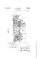
- Figure 1 is a plan view of a tilting table embodying a form of the present invention
- Figure 2 is a side elevational view of the tilting table shown in Figure .1;
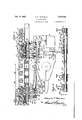
- Figure 3 is a transverse sectional view taken along the lines 33 of Figure 1 looking in the direction of the arrows;
- Figure 4 is a vertical sectional view taken along the lines 44 of Figure 3 looking in the direction of the arrows;
- Figure 5 is a longitudinal view taken along the lines 55 of Figure 1 looking in the direction of the arrows.
- the numeral l is employed to designate, in a somewhat general manner, a tilting table positioned adjacent athree high rolling millindic'ated diagrammatically as at 2 and comprising vertically spaced rolls 3.
- the table is arranged to receive billets, slabs or any metallic elements (not shown) fromcertain passesof the lower or ⁇ upper two adjacent or bank of rolls, and then shift the thus far processed elements so as to be delivered to certain passes of or between the 'other two ad jacent or bank of rolls so that, by being moved through consecutive passes-of the rolls, the billets or slabs will be ultimately processed' to their 'desired shape or configuratio-nl
- the table comprises a pair of transversely spaced, longitudinally extending, main or foundation beams of sills 4which project horizontally fora distance substantiallyequal to the length of the table and' form the primary structural mem bers of the table.
- separators-or cross barriers 5 Positioned at desirable inter vals longitudina'll'y'of the table are separators-or cross barriers 5, preferably in the horizontal plane or vertical confines of the main beams and secured thereto in order to'present a rigid, rugged framework;
- the bearing stands are superimposed upon-a monolithic or other type'pf 'subjacent'ba se' or foundation l; and secured thereto by any means desired.
- "1 2 H Forming movable orrotatable meansfor the table se -as to carry the billets, slabs, etc; away from'therolls as they emerge from certain passes thereof. ⁇ and to carryzor move the thus formed metallicelements toward the rolls to beadmitted to other passes thereof, are a plurality of rollers H! extending transversely of the-table and :journaled in suitable bearings H ,carried by the main beams. 'The rollers are in upwardly or vertically I spaced relation whenconsidering the main beams so .as to befree to receive 'anddeliver metallic elements from and to the rolls of the-mill. 7
- Driving mechanism is introduced into the table to actuate the rollers and, as exemplary of such a mechanism, there is provided, extending longi' tudinally adjacent one side of the table, aline I shaft 12 having intermittently positioned miter gears i3 secured thereto and meshing with miter gears l3 'fixed to the associated extremities of roller shafts .ljl Due to the proximity of associated structure to be hereinafter described, the roller 10 is driven by a seriesofgears l4 po sitioned ona side of the table opposite from the line smut end which are connected to the line shaft through an axle II and the miter gear I3".
- a gear case [5 and cover l5 form a housing for beam through suitable brackets and preferably disposed in alignment with the floor level l6.
- bracket l1 Attached to one of the beams at or adjacent the pivoted extremity thereof is a bracket l1 forming a support for a reversible motor ll which forms the power means for drivingv the'line shaft iii where the metallic elements can be fed to the upper bank of rolls.
- Elevating means has been incorporated into the table so that when employed with a threehighfrolling mill, the table will be capable of tilting or elevating, the metallic elements from a plane adjacent thelower bank of music a plane adjacentthe upper bank or rolls or-vice versa.
- a tilting motor means l9 firmly secured to the bases by any desired method and positioned adjacent the side of the table removed from the line shaft.
- nected to thetilting motor is a series of, gears encased in ahousing 20, the latter of which has projecting therefrom a. crank shaft 2
- Pivotally attached to the-crank arm is a reciprocating rod 22 substantiallyhorizontally disposed and having itsouter-or tree extremity pin-connected to an uprlghtarm 23':
- the arm '23 is-keyed brother'- wise secured to an axle 24 which extends hori zontally and transversely of the main beams in lower spaced relationthereto, and is journaled in apiurality ofsuitableand aligned bearings 25 which are supportedby stands 26. Transverse'ly tially equalizec l From the above, therefore, it
- the carriage ,i'ram e is provided with a plurality oi, preferably two, sock-1 ets 36 which accommodatesuitablebushings 31 and transversely extending rotatably associated axles 38, the latter of which extend towithinthe limits of the guides.
- Suitably lieyed toeach extremity is a wheel ,3! arranged tobear upon a flange of an adjacent guide and provided a radially 'disposedor peripheiilrimdll g from, but adapted tocontacgthe guideflangss to a maintainthe carriage in a predetermiued reiation with'the guides; ItIwilLbe noted resu s. above. that the carriages arranze to v move or travel m the tracks (iies in' a. direction transversely; of the table, and that are grouped in pairsiadjacnt, each oil the table.
- each carri shoulder extends towithinthe horizbn 8'1 limi of the table rollersv and is formed with, agroove or upwardly openingway U, as well as a plane horizontal-top surfaceflfls Spanningor bridging identically identified carriages are a pair oi. guide bars or side guards fliemore specifleally designated asan outerguidebar orv siderguard 43 and an inner. guidebar-or side guard!
- the side guards each have spaced Ieetor pedes-v ta'ls 44 which bear upon the planetop surfaces of the carriage frames and each being reinoval'aly secured thereto by means '01 afibolt. 45 having a head portion, 46 disposed .within associated-- way 41 and arotatable element or nut-l1 superimposed upon the adjacent pedestal-so ,thatie shortening of the effective length of the a bindthe foot and subiacent carriage tcgethar.,.
- the. guards areaccordlngly 19438 1 to .move -any metallic element emitted from one set of passes 6f the mill rolls transversely f the table do be fed to another :set of passes in the process of formlngthe metallic elements in their desired ultimate shape.
- outer side guard 43 which, considered in plan, Figure 1, has aslnuous or convoluted, 'vertical, inwardly facing surface 49 to presentpoeketsSD which affords a means for the .introduc tion of La jack :bar or any suitable 'to'o'l between the side Ian'd billet so .as to rotate the latter through a rninety :or :any degree arciand permit its reentry into the :mill in .a different position.
- a pair of telescoping shafts or axles '52 are ; a pair of telescoping shafts or axles '52, more particularly designated as an inner solid shaft 52 and 'an outer hollow shaft 52
- a .pair of levers '53 and 'lidpeach having an upstanding 'arm '55 with the latter identified lever being -of the bell crank type and provided with a horizontally disposed .arm 56.
- a lever 53* having 'a vertically disposed arm 455 and. Spaced from this'levenis a'multieparta'or compound lever 54 forming one of the bell crank type.
- the compound lever comprises an upstanding arm 55*" arranged to move with the inner shaft, and a horizontally disposed arm 55 adapted to be selectively connected to the associated upstanding arm through the medium of a clutch 51 and keyed to the inner shaft to be capable of being rotated therewith.
- Pivotally connected to the free or upper extremities of the upstanding arms 55 are a plurality of, preferably two, reciprocating rods 58 which extend from the lever arms and are pin-connected to the carriages B which carries the guide bar 43 or inner side guard.
- each iho'rizontal arm is of inverted :channel :shape in vertical cross section and provided with guide ribs El Retained within eachhorizontal arm andsupported :by'the ribs thereof is a-slide or block 62 islidably associated with :the lever :arm to be capable :of beingimove'd to :aioredetermined'position within the arm clongitndinally thereof.
- Each block has threadedly associated therewith .za' rotatable member or spindle :63 mounted .inwthe toggle and adapted, upon 2a :Inanipulaticn thereof, to retain the block in a predetermined :position, as well .as shift the slide to fa different :lo cation Within the bell crank am. By altering.
- the related slide may be moved to any location desired :along :the length of its supporting arm;
- the anchor'm'eans are employed to retain thehorizontal arms in a predetermined positionor a point along the length thereof 'in :a "position substantially fixed relative to :the base or foundation!) so that, upona tilting action :of the table; the upright arms of the bell cranks may be moved about their respective axes to cause a transverse movement of the carriagesand associated :side guards.
- the anchor means corresponding'in number with the number of horizontalsarms, whichin thepresent instance is two, are each formed by vertically spaced heads or end shanks 64 having their related extremities exteriorly threaded and rotatably associated with a connecting rod or tube 65.
- This adjustable relationship between the related heads and connecting rod permits a variation or adjustment in the overall or eiiective length of the anchor means so as to compensate for manufacturing tolerances as well as positively determine the disposition of the vertical arms and the location of the side guards to accommodate the particular passes of the mill employed.
- Jamb nuts 66 are run along the threaded portion of the end shanks after the proper length of the anchor means has been determined to abut the extremities of the connecting rods and locate the associated elements against relative rotative movement.
- each slide Spaced below each slide, and desirably in the vertical plane thereof when the table is in lowered position are a plurality of base plates 61 securely fastened to the base or founelation 9 and each being provided with a seat 68 having an upwardly facing concave spherical surface 69.
- Each block 62 is similarly formed with a concave spherical surface 10 facing downwardly with complementary concave surfaces 69 and 10 presenting sockets for the accommodation. of ball-shaped or spherical or convex extremities ll of the end shanks. The spherical extremities of the heads are locked in their respective sockets by means of a complementary formed nut 12 threadedly associated with the blocks and base plates.
- the anchor means are therefore articulately, pivotally or flexibly secured to or associated with the blocks and base plates so that no abnormal stresseswill be set up in the billet or slab shifting mechanism as the result of the table tilting about an axis extending horizontally and transversely of the table and the telescoping shafts disposed horizontally and longitudinally of the table.
- a table the combination of means for tilting said table, a pair of telescoped shafts carried by said table, a pair of transversely movable side guards extending above a material engaging plane ofsaid table, a lever attached to each of said shafts and connected to an associated side guard, and an 'adjustableanchored means secured to each lever and fixed with respect to said table for imparting motion to said side guards in response to a tilting movement of said table.
- a table the combination of means for tilting said table, a pair of telescoped shafts car ried by said table, a pair of transversely movable side guards extending above a material engaging plane of said table, a lever attached to each of said shafts and-connected to an associated side guard, an adjustable anchored means secured to each lever and fixed with respect to said table for imparting motion to said side guards in response to a tilting movement of said table, and clutch mechanism associated with said shafts adapted to render one of said side guards inoperative upon a tilting action of said table.
Description
Nov. 9, 1943. E. T. PETERSON TILTING TABL E Filed March 5, 1942 4 Sheets-Sheet l i .5. WWW
gwwm
Nov. 9, 1943. E. T. PETERSON TILTQING TABLE Filed March 5, 1942 4 Sheets-Sheet 2 Qu n m) m F\ NOV. 9, 1943. PETERSON 2,334,026
TILTING TABLE 4 Sheets-Sheet 4 R Mm E. T. PETERSON TILTING TABLE Filed March 5, 1942 llllllllllllllllllllllllllllllllllllllllllllllllllllllllllllllllllll 1.
Nov.
Patented Nov. 9, 1943 UNITED- STATES PATENT OFFICE:
'rrLrING TABLE .Edward'T. Peterson, Reading, Pa. ApplicationMarch '5, 1942, seria1 rid-433,521
claims.
The invention relates to a tilting table employed in a steel mill incident to the formation or fabrication of metallic elements or shapes from billets or slabs. Y
Tilting tables ofjthehpresent type are employed in steel mills as atransfer medium through which metallic elements such as billets, slabs, etc., are, upon being emitted from between two vertically spaced rolls, for instance, of a three-high mill, raised or lowered vertically so as to'be placed in a position to enter,-or be admitted between one of the previously mentioned rolls and an adjacent, or-another vertically spaced roll, in the process of forming or working billets or slabs "into the ultimate or desired configuration,
An object of the invention is the provision, in a tilting table, of a guide means i'or moving metallic elements transversely ofthe table, and having actuating means responsive to the tilting action or movement or the table,
' Another object of the invention is the provision, in a tilting table, of an arrangement of elements for moving a side guard or guide fbar transversely of a tilting table with the elements being adjustable so that the distance through which the side guard or guide bar may move can be definitelydetermined. I
A further object of the invention is to provide,
in a tilting table, a plurality of guide bars ar- 1 ranged to move transversely of the table with means associated with one of the guide bars for selectively rendering it inoperative. I
The above,'as well as numerousother objects of the invention, will become apparent from the succeeding description and from an inspection ,of
the accompanying drawings which, in several,
views thereof, show an exemplified form 01' the invention and wherein: j
Figure 1 is a plan view of a tilting table embodying a form of the present invention;
' Figure 2 is a side elevational view of the tilting table shown in Figure .1;
Figure 3 is a transverse sectional view taken along the lines 33 of Figure 1 looking in the direction of the arrows;
Figure 4 is a vertical sectional view taken along the lines 44 of Figure 3 looking in the direction of the arrows;
Figure 5 is a longitudinal view taken along the lines 55 of Figure 1 looking in the direction of the arrows. I
Referring now to the drawings in detail, Wherein like reference characters indicate like parts, the numeral l is employed to designate, in a somewhat general manner, a tilting table positioned adjacent athree high rolling millindic'ated diagrammatically as at 2 and comprising vertically spaced rolls 3. The table is arranged to receive billets, slabs or any metallic elements (not shown) fromcertain passesof the lower or {upper two adjacent or bank of rolls, and then shift the thus far processed elements so as to be delivered to certain passes of or between the 'other two ad jacent or bank of rolls so that, by being moved through consecutive passes-of the rolls, the billets or slabs will be ultimately processed' to their 'desired shape or configuratio-nl The table comprises a pair of transversely spaced, longitudinally extending, main or foundation beams of sills 4which project horizontally fora distance substantiallyequal to the length of the table and' form the primary structural mem bers of the table. Positioned at desirable inter vals longitudina'll'y'of the table are separators-or cross barriers 5, preferably in the horizontal plane or vertical confines of the main beams and secured thereto in order to'present a rigid, rugged framework; Y Outstanding from o'ne-or adjacent extremitieswof thefsills are a plurality of opp'o sitely directed axles 6 journaled inaccommodat ing bearings Twhich pivotally', support or "carry one end of rthe'tableland are, in turn-supported in anuelevated position by means of bearing stands 8. The bearing stands are superimposed upon-a monolithic or other type'pf 'subjacent'ba se' or foundation l; and secured thereto by any means desired. "1 2 H "Forming movable orrotatable meansfor the table se -as to carry the billets, slabs, etc; away from'therolls as they emerge from certain passes thereof. {and to carryzor move the thus formed metallicelements toward the rolls to beadmitted to other passes thereof, are a plurality of rollers H! extending transversely of the-table and :journaled in suitable bearings H ,carried by the main beams. 'The rollers are in upwardly or vertically I spaced relation whenconsidering the main beams so .as to befree to receive 'anddeliver metallic elements from and to the rolls of the-mill. 7
Driving mechanism is introduced into the table to actuate the rollers and, as exemplary of such a mechanism, there is provided, extending longi' tudinally adjacent one side of the table, aline I shaft 12 having intermittently positioned miter gears i3 secured thereto and meshing with miter gears l3 'fixed to the associated extremities of roller shafts .ljl Due to the proximity of associated structure to be hereinafter described, the roller 10 is driven by a seriesofgears l4 po sitioned ona side of the table opposite from the line smut end which are connected to the line shaft through an axle II and the miter gear I3".
- A gear case [5 and cover l5 form a housing for beam through suitable brackets and preferably disposed in alignment with the floor level l6.
Attached to one of the beams at or adjacent the pivoted extremity thereof is a bracket l1 forming a support for a reversible motor ll which forms the power means for drivingv the'line shaft iii where the metallic elements can be fed to the upper bank of rolls.
An arrangement is provided in the tilting table whereby billets, slabs, etc., moved onto the table from one passage of the rolls, may be shifted transversely of the table to be fed into a passage of diflerent. configuration or contour. Toward the accomplishment of this end, therefore, there is secured to the main beams in subjacent relation thereto, a plurality or pair of transversely extending longitudinally spaced supporting beams 3i onto which are secured intermediate I-shaped structural members 32 positioned desirably in the plane 01 the main beams. Mounted upon the through a series of intermeshed gears l8. By a manipulation of the motor If", the rollers may be driven ineither a clockwise or counterclockwise direction, when considering Figure 2-.or '4, to receive or deliver metallic elementsfrom or to the rolls of the mill.
Elevating means, has been incorporated into the table so that when employed with a threehighfrolling mill, the table will be capable of tilting or elevating, the metallic elements from a plane adjacent thelower bank of music a plane adjacentthe upper bank or rolls or-vice versa. For the-accomplishment of the above, therefore, there is provided a tilting motor means l9 firmly secured to the bases by any desired method and positioned adjacent the side of the table removed from the line shaft. Operatively con fr:
nected to thetilting motor is a series of, gears encased in ahousing 20, the latter of which has projecting therefrom a. crank shaft 2| with an eccentric or crank arm 2 I! positioned on the table adjacent-the side1 otthe housing 20" and operatively' connected to the gears 20. Pivotally attached to the-crank arm is a reciprocating rod 22 substantiallyhorizontally disposed and having itsouter-or tree extremity pin-connected to an uprlghtarm 23': The arm '23 is-keyed brother'- wise secured to an axle 24 which extends hori zontally and transversely of the main beams in lower spaced relationthereto, and is journaled in apiurality ofsuitableand aligned bearings 25 which are supportedby stands 26. Transverse'ly tially equalizec l From the above, therefore, it
- willbe noted that upon an actuation of the liftstructural members, and securely fastened there- 33 grouped preferably in two sets of three tracks adjacent each longitudinal extremity of the table and also of I-shape in vertical cross section so as to present horizontally opening or facing channel ways.- The guides or tracks extend to within the close proximity of the main beams tor the purpose to be hereinafter apparent. Located between, or within the confines of each pair or adjacent guides, is a carriage frame having a shoulder. 35 thereof extendlng vertically be-- tween adjacent rollers. The carriage ,i'ram e is provided with a plurality oi, preferably two, sock-1 ets 36 which accommodatesuitablebushings 31 and transversely extending rotatably associated axles 38, the latter of which extend towithinthe limits of the guides. Suitably lieyed toeach extremity is a wheel ,3! arranged tobear upon a flange of an adjacent guide and provided a radially 'disposedor peripheiilrimdll g from, but adapted tocontacgthe guideflangss to a maintainthe carriage in a predetermiued reiation with'the guides; ItIwilLbe noted resu s. above. that the carriages arranze to v move or travel m the tracks (iies in' a. direction transversely; of the table, and that are grouped in pairsiadjacnt, each oil the table.
So as to more clearly identity theearriagesptbe ones of each-pair aredesignated as A'and the latter carriages interposed 1 between former, as clearly indicated-in Figures lcandtd.
' curedto the innerextremities of the tilting levers may form, a means wherebythe mass of the table, carried by the links 28, may be substaningmotor, therciprocal rod 22 will be moved toward the right'when considering Figures 1, 2 or 4; and impart alclockwise, motion, to the axleand a vertical movement to the links to'causethe'mill adjacent extremity of the table to beraised. "This action'will move thetable from a position as illustrated, or capable of receiving metallic elements from th lower bank of rollsto a'tilted position 1 nn d" As previously indicated, each carri shoulder extends towithinthe horizbn 8'1 limi of the table rollersv and is formed with, agroove or upwardly openingway U, as well as a plane horizontal-top surfaceflfls Spanningor bridging identically identified carriages are a pair oi. guide bars or side guards fliemore specifleally designated asan outerguidebar orv siderguard 43 and an inner. guidebar-or side guard! The side guards each have spaced Ieetor pedes-v ta'ls 44 which bear upon the planetop surfaces of the carriage frames and each being reinoval'aly secured thereto by means '01 afibolt. 45 having a head portion, 46 disposed .within associated-- way 41 and arotatable element or nut-l1 superimposed upon the adjacent pedestal-so ,thatie shortening of the effective length of the a bindthe foot and subiacent carriage tcgethar.,.
The particular attachment of the guards ta'the.
carriages lends (itself to an adjustment oI the guards transversely of the table so as toaccom-y modate theparticular passes of the-miil rolls employed. Referring particularly to Figurei, ;it
will be observed thatthe inner side guard;fl
is secured tothe carriages B and'the oute'rside guard 43 is attached to'the carriages A 831L the main body 48 of. the guardsexten'ds above the top surface or materially enga in m ceratthe rollers, the. guards areaccordlngly 19438 1 to .move -any metallic element emitted from one set of passes 6f the mill rolls transversely f the table do be fed to another :set of passes in the process of formlngthe metallic elements in their desired ultimate shape. Attention is directed to the outer side guard 43 which, considered in plan, Figure 1, has aslnuous or convoluted, 'vertical, inwardly facing surface 49 to presentpoeketsSD which affords a means for the .introduc tion of La jack :bar or any suitable 'to'o'l between the side Ian'd billet so .as to rotate the latter through a rninety :or :any degree arciand permit its reentry into the :mill in .a different position.
.The supporting beams 31! arexiesirably extended transversely tor the itable beyond the vertical limits-of the :main beams on one side o'f Cthe table, lpreiera'bly the side "removed irom 'therollier driving motor land secured to .the supporting beams'zad-iacent their overhanging. extremities are *a plurality .of horizontally aligned =rdownstanding shaft supports :or bearings 5.1. Journaled in the shaft supports and extending longitudinally of the table are ;a pair of telescoping shafts or axles '52, more particularly designated as an inner solid shaft 52 and 'an outer hollow shaft 52 Suitably keyed to the hollow or outer shaft is a .pair of levers '53 and 'lidpeach having an upstanding 'arm '55 with the latter identified lever being -of the bell crank type and provided with a horizontally disposed .arm 56. Also keyed to the inner solid shaft is a lever 53* having 'a vertically disposed arm 455 and. Spaced from this'levenis a'multieparta'or compound lever 54 forming one of the bell crank type. The compound lever comprises an upstanding arm 55*" arranged to move with the inner shaft, and a horizontally disposed arm 55 adapted to be selectively connected to the associated upstanding arm through the medium of a clutch 51 and keyed to the inner shaft to be capable of being rotated therewith. Pivotally connected to the free or upper extremities of the upstanding arms 55 are a plurality of, preferably two, reciprocating rods 58 which extend from the lever arms and are pin-connected to the carriages B which carries the guide bar 43 or inner side guard. In like manner the free extremities of the vertical arms 55 and 55 are pivotally connected to a pair of reciprocating rods 59 which, in turn, are flexibly secured to the carriages A carrying the outer side guard or guide bar 43, By this arrangement, therefore, a counterclockwise motion of all of the upstanding arms, when considering Figure 3 of the drawings, will result in a movement of the side guards in a direction toward the opposite side of the table, carrying with them or shifting transversely of the table any metallic elements deposited on the rollers from the mill to thereby change the location of the elements on the table so that they may be in a position to enter different passes in the rolls from which they had just emerged. It may at times be found resirable merely toemploy one or the inner side guard for shifting bars, etc, transversely of the table, due to the rolling of a single shape or one type of element. In such instances, then, the clutch mechanism 57 is actuated so as to be out of contact with the horizontal arm 55* to render the inner shaft inoperative and prevent a transverse movement of the outer side guard.
The side guards are moved transversely of the table or the telescoping shafts are rotated about their common axis in response to a vertical or tilting action of the table and, as exemplary of a means :c'apable of imparting :such aimovement to the side guards and shafts, the horizontal arms of the bell cranksv have associated therewith author means generally designated by the reference characters 60 and 50 the iormer of which is connected to the-arm -55'sand theilatter being connected to the arm 55 To accommodate the ano'horm'eans, each iho'rizontal arm is of inverted :channel :shape in vertical cross section and provided with guide ribs El Retained within eachhorizontal arm andsupported :by'the ribs thereof is a-slide or block 62 islidably associated with :the lever :arm to be capable :of beingimove'd to :aioredetermined'position within the arm clongitndinally thereof. [Each block :has threadedly associated therewith .za' rotatable member or spindle :63 mounted .inwthe toggle and adapted, upon 2a :Inanipulaticn thereof, to retain the block in a predetermined :position, as well .as shift the slide to fa different :lo cation Within the bell crank am. By altering. or changing the effective length of each spindle, the related slide may be moved to any location desired :along :the length of its supporting arm; The anchor'm'eans are employed to retain thehorizontal arms in a predetermined positionor a point along the length thereof 'in :a "position substantially fixed relative to :the base or foundation!) so that, upona tilting action :of the table; the upright arms of the bell cranks may be moved about their respective axes to cause a transverse movement of the carriagesand associated :side guards. "The anchor means corresponding'in number with the number of horizontalsarms, whichin thepresent instance is two, are each formed by vertically spaced heads or end shanks 64 having their related extremities exteriorly threaded and rotatably associated with a connecting rod or tube 65. This adjustable relationship between the related heads and connecting rod permits a variation or adjustment in the overall or eiiective length of the anchor means so as to compensate for manufacturing tolerances as well as positively determine the disposition of the vertical arms and the location of the side guards to accommodate the particular passes of the mill employed. Jamb nuts 66 are run along the threaded portion of the end shanks after the proper length of the anchor means has been determined to abut the extremities of the connecting rods and locate the associated elements against relative rotative movement. Spaced below each slide, and desirably in the vertical plane thereof when the table is in lowered position are a plurality of base plates 61 securely fastened to the base or founelation 9 and each being provided with a seat 68 having an upwardly facing concave spherical surface 69. Each block 62 is similarly formed with a concave spherical surface 10 facing downwardly with complementary concave surfaces 69 and 10 presenting sockets for the accommodation. of ball-shaped or spherical or convex extremities ll of the end shanks. The spherical extremities of the heads are locked in their respective sockets by means of a complementary formed nut 12 threadedly associated with the blocks and base plates. The anchor means are therefore articulately, pivotally or flexibly secured to or associated with the blocks and base plates so that no abnormal stresseswill be set up in the billet or slab shifting mechanism as the result of the table tilting about an axis extending horizontally and transversely of the table and the telescoping shafts disposed horizontally and longitudinally of the table.
' From the above, itl will ,belnoted that various valterations and changesmay-be made to the ex.
emplifled form of the hereinabove described, and illustrated construction without departing from within the spirit of the invention and the scope ofthe appended claims. I v
,1. In a table, the combination of means for tilting said table, a pair of telescoped shafts carried by said table, a pair of transversely movable side guards extending above a material engaging plane ofsaid table, a lever attached to each of said shafts and connected to an associated side guard, and an 'adjustableanchored means secured to each lever and fixed with respect to said table for imparting motion to said side guards in response to a tilting movement of said table.
' .2. In a table, the combination of means for tilting said table, a pair of telescoped shafts car ried by said table, a pair of transversely movable side guards extending above a material engaging plane of said table, a lever attached to each of said shafts and-connected to an associated side guard, an adjustable anchored means secured to each lever and fixed with respect to said table for imparting motion to said side guards in response to a tilting movement of said table, and clutch mechanism associated with said shafts adapted to render one of said side guards inoperative upon a tilting action of said table.
,3. In a table,. the combination of means for tilting said table, a pair of telescoped shafts carried -by said'table, a guide bar movable transversely of said table, a lever mounted on one of saidjshaftfi and connected tosaid guide ban a spindle-associated with said lever, meansslidably mounted in said lever and maintained in a predetermined position i by said spindle. anchor means universally connected to said first-named means and being adapted to rotate, said lever upon a tilting movement ofsaid table, and clutch means carried by one of said'shaftsl, and asso-.
ciated with said lever for rendering the latter inoperative upon a tilting movement of said table. 4. In a table, the combination of a plurality of guide bars adapted to move transversely of said table, a plurality of telescoped shafts carried-by said table adjacent one side thereof, a lever con guide bars secured to said carriages, telescoped shafts carried by said table, levers connected to each shaft, reciprocating rods connecting said levers and carriages, rotatable means in each lever, a block carried by each lever and maintained in a predetermined position by an associated rotatable means, and adjustable anchor means connected to said blocks; anda clutch mechanism related with said shafts so as selec tively to'render one only of said shafts inoperative upon a tilting action of said table. 1
EDWARD 'r. PETERSON?
Priority Applications (1)
| Application Number | Priority Date | Filing Date | Title |
|---|---|---|---|
| US433521A US2334026A (en) | 1942-03-05 | 1942-03-05 | Tilting table |
Applications Claiming Priority (1)
| Application Number | Priority Date | Filing Date | Title |
|---|---|---|---|
| US433521A US2334026A (en) | 1942-03-05 | 1942-03-05 | Tilting table |
Publications (1)
| Publication Number | Publication Date |
|---|---|
| US2334026A true US2334026A (en) | 1943-11-09 |
Family
ID=23720423
Family Applications (1)
| Application Number | Title | Priority Date | Filing Date |
|---|---|---|---|
| US433521A Expired - Lifetime US2334026A (en) | 1942-03-05 | 1942-03-05 | Tilting table |
Country Status (1)
| Country | Link |
|---|---|
| US (1) | US2334026A (en) |
Cited By (2)
| Publication number | Priority date | Publication date | Assignee | Title |
|---|---|---|---|---|
| US2686443A (en) * | 1948-12-07 | 1954-08-17 | Loewy Eng Co Ltd | Manipulator for rolling mills |
| US2777343A (en) * | 1951-07-18 | 1957-01-15 | Birdsboro Steel Foundry & Mach | Tilting table |
-
1942
- 1942-03-05 US US433521A patent/US2334026A/en not_active Expired - Lifetime
Cited By (2)
| Publication number | Priority date | Publication date | Assignee | Title |
|---|---|---|---|---|
| US2686443A (en) * | 1948-12-07 | 1954-08-17 | Loewy Eng Co Ltd | Manipulator for rolling mills |
| US2777343A (en) * | 1951-07-18 | 1957-01-15 | Birdsboro Steel Foundry & Mach | Tilting table |
Similar Documents
| Publication | Publication Date | Title |
|---|---|---|
| US2334026A (en) | Tilting table | |
| US2852065A (en) | Roller leveller having means to move individual rolls into and out of work engagement | |
| US1937194A (en) | Apparatus for handling materials | |
| US449511A (en) | Rolling-mill | |
| US942644A (en) | Transfer-table for rolling-mills. | |
| US770195A (en) | Method of rolling tubing. | |
| US424650A (en) | Ingot-manipulator | |
| US462962A (en) | aiken | |
| US439925A (en) | Feed-table for rolling-mills | |
| US529124A (en) | Rolling-mill | |
| US525207A (en) | Rolling-mill | |
| US3342054A (en) | Rolling mills | |
| US931544A (en) | Tube-trough for tube-mills. | |
| US721626A (en) | Manipulator for feed-tables of rolling-mills. | |
| US345953A (en) | beislin | |
| US1665606A (en) | A corpora | |
| US386324A (en) | Ingot-manipulator | |
| US1498620A (en) | Rolling mill | |
| US588225A (en) | Feed-table for rolling-mills | |
| US1082387A (en) | Hotbed. | |
| US2777343A (en) | Tilting table | |
| US1251514A (en) | Rolling-mill. | |
| US846942A (en) | Mill for rolling annular articles. | |
| US403204A (en) | Feed-table for rolling-mills | |
| US600335A (en) | Chusetts |