US2332913A - Method of manufacturing puncture sealing inner tubes - Google Patents
Method of manufacturing puncture sealing inner tubes Download PDFInfo
- Publication number
- US2332913A US2332913A US403540A US40354041A US2332913A US 2332913 A US2332913 A US 2332913A US 403540 A US403540 A US 403540A US 40354041 A US40354041 A US 40354041A US 2332913 A US2332913 A US 2332913A
- Authority
- US
- United States
- Prior art keywords
- plastic
- inner tube
- rubber composition
- layer
- composition
- Prior art date
- Legal status (The legal status is an assumption and is not a legal conclusion. Google has not performed a legal analysis and makes no representation as to the accuracy of the status listed.)
- Expired - Lifetime
Links
Images
Classifications
-
- B—PERFORMING OPERATIONS; TRANSPORTING
- B29—WORKING OF PLASTICS; WORKING OF SUBSTANCES IN A PLASTIC STATE IN GENERAL
- B29D—PRODUCING PARTICULAR ARTICLES FROM PLASTICS OR FROM SUBSTANCES IN A PLASTIC STATE
- B29D30/00—Producing pneumatic or solid tyres or parts thereof
- B29D30/06—Pneumatic tyres or parts thereof (e.g. produced by casting, moulding, compression moulding, injection moulding, centrifugal casting)
- B29D30/0681—Parts of pneumatic tyres; accessories, auxiliary operations
- B29D30/0685—Incorporating auto-repairing or self-sealing arrangements or agents on or into tyres
-
- B—PERFORMING OPERATIONS; TRANSPORTING
- B29—WORKING OF PLASTICS; WORKING OF SUBSTANCES IN A PLASTIC STATE IN GENERAL
- B29C—SHAPING OR JOINING OF PLASTICS; SHAPING OF MATERIAL IN A PLASTIC STATE, NOT OTHERWISE PROVIDED FOR; AFTER-TREATMENT OF THE SHAPED PRODUCTS, e.g. REPAIRING
- B29C73/00—Repairing of articles made from plastics or substances in a plastic state, e.g. of articles shaped or produced by using techniques covered by this subclass or subclass B29D
- B29C73/16—Auto-repairing or self-sealing arrangements or agents
- B29C73/22—Auto-repairing or self-sealing arrangements or agents the article containing elements including a sealing composition, e.g. powder being liberated when the article is damaged
-
- B—PERFORMING OPERATIONS; TRANSPORTING
- B60—VEHICLES IN GENERAL
- B60C—VEHICLE TYRES; TYRE INFLATION; TYRE CHANGING; CONNECTING VALVES TO INFLATABLE ELASTIC BODIES IN GENERAL; DEVICES OR ARRANGEMENTS RELATED TO TYRES
- B60C19/00—Tyre parts or constructions not otherwise provided for
- B60C19/12—Puncture preventing arrangements
- B60C19/127—Puncture preventing arrangements for inner tubes
-
- B—PERFORMING OPERATIONS; TRANSPORTING
- B29—WORKING OF PLASTICS; WORKING OF SUBSTANCES IN A PLASTIC STATE IN GENERAL
- B29D—PRODUCING PARTICULAR ARTICLES FROM PLASTICS OR FROM SUBSTANCES IN A PLASTIC STATE
- B29D30/00—Producing pneumatic or solid tyres or parts thereof
- B29D30/06—Pneumatic tyres or parts thereof (e.g. produced by casting, moulding, compression moulding, injection moulding, centrifugal casting)
- B29D30/0681—Parts of pneumatic tyres; accessories, auxiliary operations
- B29D30/0685—Incorporating auto-repairing or self-sealing arrangements or agents on or into tyres
- B29D2030/0686—Incorporating sealants on or into tyres not otherwise provided for; auxiliary operations therefore, e.g. preparation of the tyre
- B29D2030/0689—Incorporating sealants on or into tyres not otherwise provided for; auxiliary operations therefore, e.g. preparation of the tyre by incorporating the sealant into a plurality of chambers, e.g. bags, cells, tubes or closed cavities
-
- B—PERFORMING OPERATIONS; TRANSPORTING
- B29—WORKING OF PLASTICS; WORKING OF SUBSTANCES IN A PLASTIC STATE IN GENERAL
- B29D—PRODUCING PARTICULAR ARTICLES FROM PLASTICS OR FROM SUBSTANCES IN A PLASTIC STATE
- B29D30/00—Producing pneumatic or solid tyres or parts thereof
- B29D30/06—Pneumatic tyres or parts thereof (e.g. produced by casting, moulding, compression moulding, injection moulding, centrifugal casting)
- B29D30/0681—Parts of pneumatic tyres; accessories, auxiliary operations
- B29D30/0685—Incorporating auto-repairing or self-sealing arrangements or agents on or into tyres
- B29D2030/0686—Incorporating sealants on or into tyres not otherwise provided for; auxiliary operations therefore, e.g. preparation of the tyre
- B29D2030/0691—Incorporating sealants on or into tyres not otherwise provided for; auxiliary operations therefore, e.g. preparation of the tyre through the use of a toroidal support, e.g. a core, a part of the tyre or an inner tube
-
- B—PERFORMING OPERATIONS; TRANSPORTING
- B29—WORKING OF PLASTICS; WORKING OF SUBSTANCES IN A PLASTIC STATE IN GENERAL
- B29L—INDEXING SCHEME ASSOCIATED WITH SUBCLASS B29C, RELATING TO PARTICULAR ARTICLES
- B29L2030/00—Pneumatic or solid tyres or parts thereof
-
- Y—GENERAL TAGGING OF NEW TECHNOLOGICAL DEVELOPMENTS; GENERAL TAGGING OF CROSS-SECTIONAL TECHNOLOGIES SPANNING OVER SEVERAL SECTIONS OF THE IPC; TECHNICAL SUBJECTS COVERED BY FORMER USPC CROSS-REFERENCE ART COLLECTIONS [XRACs] AND DIGESTS
- Y10—TECHNICAL SUBJECTS COVERED BY FORMER USPC
- Y10S—TECHNICAL SUBJECTS COVERED BY FORMER USPC CROSS-REFERENCE ART COLLECTIONS [XRACs] AND DIGESTS
- Y10S137/00—Fluid handling
- Y10S137/907—Vacuum-actuated valves
-
- Y—GENERAL TAGGING OF NEW TECHNOLOGICAL DEVELOPMENTS; GENERAL TAGGING OF CROSS-SECTIONAL TECHNOLOGIES SPANNING OVER SEVERAL SECTIONS OF THE IPC; TECHNICAL SUBJECTS COVERED BY FORMER USPC CROSS-REFERENCE ART COLLECTIONS [XRACs] AND DIGESTS
- Y10—TECHNICAL SUBJECTS COVERED BY FORMER USPC
- Y10T—TECHNICAL SUBJECTS COVERED BY FORMER US CLASSIFICATION
- Y10T152/00—Resilient tires and wheels
- Y10T152/10—Tires, resilient
- Y10T152/10495—Pneumatic tire or inner tube
- Y10T152/10666—Automatic sealing of punctures [e.g., self-healing, etc.]
- Y10T152/10675—Using flowable coating or composition
- Y10T152/10702—Using flowable coating or composition within or part of construction of inflating inner tube
- Y10T152/10711—Sealant in plural layers or plural pockets
Definitions
- This invention relatesto a method of manufacturing puncture sealing inner tubes. More particularly it relates to puncture sealing inner will be piercedshould a puncturing medium pass tubes of a type having plastic composition enthrough the crown portion of the inner tube. closed in a plurality of compartments in the The invention will be more fully understood crown portion or region of the tube for rendering when taken iny conjunction with the accompanythe tube substantially puncture-proof under most ing drawing, in whichiconditions of operation.
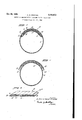
- Fig. 1 is a transverse cross-sectional view of a This application is a division of my co-pending full-molded puncture sealing inner tube of the application Serial No. 360,568, nled October l0, l0 plastic type made in accordance with the present 1940. invention;
- FIG. 2 is a transverse cross-sectional view showplastic puncture sealing composition enclosed in ing the component parts of the inner tube. of their crown portions for protecting the tubes Fig. 1 during the manufacture thereof; and against punctures, blow-outs and the like.
- H0w ⁇ I5 Fig. 3 is an enlarged perspective view of a ever, in such inner tubes of former constructions portion of a composite layer of plastic material external forces and other conditions sometimes used in the manufacture of the inner tube of caused undesired displacement of the plastic Fig. 1. material. For example, heat and centrifugal Referring in particular-to Fig.
- the strips ofthe two layers I4 and I5 are prefseparating partitions or membranes are bonded ⁇ erably arranged in super-imposed and staggered to the spaced walls of the inner tube and cornrelation sothat the partitions I8 of one layer are pletely enclose the individual strips of plastic laterally off-set with respect to similar partitions composition so as to retain the plastic composir in the other layer.
- all lotion in proper position during operation of the 'i0 cations in the crown portion of the inner tube are protected by theplastic material of at least in staggered relation to the strips of the other,
- trating medium passing through the crown portion ofl the inner tube will necessarily have to for sealing purposes.
- This reduction in thickness pierce at least two strips ofplastic puncture sealproduces softer easier riding conditions as well ing composition beforereaching the interior of as a reduction in the amount of heat generated the tube.
- the strips of plastic nected partitions or membranes I3 and I9 jointly puncture sealing composition arefarranged pref- ⁇ serve tol enclose and retain the plastic strips .I6
- the inflated inner tube may be mounted upon a suitable support, suchas a rotatably mounted drum or wheel, so that it may be conveniently worked upon.
- a suitable support suchas a rotatably mounted drum or wheel, so that it may be conveniently worked upon.
- circumferentially extending sidewall portions 22 ⁇ and 23 at opposite sides of the tube, and, if desired, the intermediate. crown region are buied, after which these portions are coated with a vulcanizable rubber cement and allowed to dry.
- sufiicient time has been allowed for the drying of the cement the tube is ready ⁇ to have a composite puncture sealing layer 24 and an outer covering layer 25 of vulcanizable rubber composition, of rubber stock similar to the wall 2 I, applied thereto.
- the formation of the composite layer 24 is accomplished by placing a sheet of normally non-vulcanizable plastic rubber composition (to be hereinafter more completely described) of predetermined thickness upon a suitableJ sheet of flexible backing material, such as Holland cloth, Textolin, treated paper or the like, so that it may be handled conveniently and without distortion during the subsequent steps involved in the building of the inner tube.
- a suitableJ sheet of flexible backing material such as Holland cloth, Textolin, treated paper or the like.
- the supported plastic sheet is then cut into elongated strips of plastic 26 and backing material 21 of proper width and these strips are painted, sprayed or otherwise given a. .coating 21a on their opposite edges 28 with a film-forming or cure-producing solution or dispersion of vulcanizable rubber composition.
- This solution or dispersion is a liquidA having a viscosity of about that of ordinary thin house paint so that the thickness of the material which dries in situ as a thin deposit upon the strips is practically negligible.
- the strips are moveddzogether into edge contacting relation to form a flat elongated layer. 29.
- the top surface 30 of the layer 29 is similarly coated with the film-forming solution, after which a layer 3
- the composite layer 24 thus assembled is next applied to the prepared crown portionof the inner tube 2
- the composite layer'24 being entirely plastic at this stage in the building of the inner tube, molds itself crown portion of the inner tube 2
- 'I'he layer 25 of vulcanizable rubber composition is applied
- the assembled structure is now ready to be placed in a cold vulcanizing mold of proper pre' determined size and iniiated somewhat more for vulcanizing purposes.
- the temperature of the mold is then raised to approximately 310 F. and the inner tube vulcanized for a proper predetermined period.
- thisvcuring period is dependent upon the thickness of the tube structure at the crown portion thereof, and in actualpractice where-two layers of plastic strips 26 were employed having a combined thickness of approximately M4 inch in a curing period from the mold is opened and the inner tube removed.
- the edges of the outer covering layer become integrally bonded to the tubular wall 2
- the nlm-forming solution coating the surfaces 28 and 3B of the plastic strips 26 reacts with the normally non-vulcanizable rubber.
- composition ofthe normally non-vulcanizable plastic of the strips 26 and the composition ofthe film-forming solution for coating the sur- Non-vulcanizing plastic Rubber Merce tobenzothiazole Softener or plasticzer- Rubber peptizing agent Rosin oil Film-forming solution Smoked sheet rubber l ul h Zinc oxide Zinc lam-ate Solvent (naphtha) While very satisfactory results have been obtained with plastic composition and film-forming solution comprising the ingredients of the above tables, it will be readily apparent to those skilled in the art that other modified forms of plastic rubber compositions and nlm-forming liquids may be employed, ifdesired, in the formation of the partitioned layer 2d of the inner tube within the scope of the invention.
- puncture sealing inner tubes having plastic sealing composition in the crown portions thereof may bereadily and economically formed so that -the plastic material thereof is permanently located and properly retained in its desired place Within the tube at all times and under all conditions of operation thereof.
- the partitioning means provided for maintaining the plastic composition in such location may be made in the form of a very thin light weight, flexible and fully vulcanized lm or skin of rubber composition which adds no appreciable thickness or stiffness to the crown region of the inner tube and accordingly alfords much superior operating conditions in the completed inner tube than has been possible heretofore in earlier plastic type puncture sealing inner tubes where partitions of sheet rubber or thelike were employed for separating the plastic composition thereof into individual compartments.
- the method of forming a puncture sealing inner tube wall comprising the steps of coating with a film-forming solution one or more of the surfaces presented by a plurality of, pieces of normally non-vulcanizable plastic rubber come position, assembling the pieces into a composite layer consisting of juxtaposed pieces of plastic composition separated by the coating material,
- the method of forming full-molded puncture sealing inner tubes comprising the steps of coatingwith a nlm-forming solution one or more of the surfaces presented by a plurality of pieces of normally non-vulcanizable plastic rubber composition, assembling the pieces into a composite layer consisting of juxtaposed pices of plastic composition separated by the coating material, inating an annular tubular wall of vul and extending between adjacent pieces of plastic rubber composition.
- the method of forming full-molded puncture sealing inner tubes comprising the steps of coating with a nlm-forming solution one or more of the surfaces presented by a plurality of pieces of normally non-vulcanizable plastic rubber composition, assembling the pieces into a composite layer consisting of juxtaposed pieces of plastic composition separated by the coating material,'inflating an annular tubular wall of v'ulcanized or partially vulcanized rubber composition, buiing and cementing the crown region of' the inflated wall, placing upon the crown region of the inflated wall the composite layer, placing a covering layer of vulcanizable rubber composition upon the exposed surface of the composite layer, pressing the lateral marginal edges of the covering layer into engagement with cemented portions of the tubular wall, and vulcanizing the assembled inner tube in a conventional inner tube mold of predetermined size, whereby relatively ⁇ thin vulcanized membranes of rubber composition are produced attached to said layers of Vulcanized rubber composition and extending between adjacent strips of ⁇ plastic rubber composition by the reaction of the intermediate layers of film-forming solution
- the method of forming full-molded puncture sealing inner tubes comprising the steps of coating with a cure-producing solution one or more of the surfaces presented by a plurality of pieces of normally non-vulcanizable plastic rubber composition, assembling the pieces into a composite layer consisting of juxtaposed pieces of plastic vcomposition separated by the coating material, inlating an annular tubular wall of vulcanized or partially vulcanized rubber composition, buiilng and cementing portions of the crown region of the inated wall, placing upon the crown region thus prepared the composite layer, placing a covering layer of vulcanizablel rubber composition upon the outer surfacevof the composite layer, pressing the lateral marginal edges of the covering layer into engagement with cemented portions of the tubular wall, and vulcanizing the assembled inner tube in a conventional inner tube mold of predetermined size, whereby the reaction of the intermediate lms with the normally non-vulcanizable rubber composition adjacent thereto during vulcanization produces relativelyA thin partitions of vulcanized rubber composition attached to said layers of vulcanized rubbercomposition
- 'Ihe method of forming full-molded puncture sealing inner tubes comprising the steps of coating with a'cure-producing solution one or more of the surfaces presented by a plurality of pieces of normally non-vulcanizable plastic rubber composition, assembling the pieces into a composite layer consisting of juxtaposed pieces of plastic composition separated by the coating material, inilating an annular tubular wall of vulcanized or partiallyvulcanized rubber composition, buffing and cementing portions of the crown region of the inflated Wall, placing upon the crown region of the inflated Wall the composite layer, placing a covering layer of vulcanizable rubber composition upon the outer surface of the composite layer, pressing the lateral marginal portions of the covering layer into circumferential engagement with cementedl portions of 'the tubular Wall, and vulcanizing the assembled inner tube in a-conventional inner tube mold of predetermined size, whereby the reaction of the intermediate lms with the normally nonvulcanizable rubber composition adjacent thereto produces, during'vulcanization, relatively thin membranes of vulcanized rubber composition bonded
Description
'inner tube. Since these partitions are exceedingly thin and flexible, the total thickness of the tube two compartments and consequently any pene- Patented Oct. 26, 1943 UNITED .STATES PATENT OFFICE METHOD F MANUFACTURING PUNCTURE f SEALING INNER TUBES Alfred Nicholas Iknayan, Indianapolis, Ind., as-
signor to United States Rubber Company, New y York, N. Y., a corporation of New Jersey Original application October 10, 1940, Serial yNo. 360,568. Divided and this application July 22, 1941, Serial No. 403,540
8 Claims. (Cl. 154--15) This invention relatesto a method of manufacturing puncture sealing inner tubes. More particularly it relates to puncture sealing inner will be piercedshould a puncturing medium pass tubes of a type having plastic composition enthrough the crown portion of the inner tube. closed in a plurality of compartments in the The invention will be more fully understood crown portion or region of the tube for rendering when taken iny conjunction with the accompanythe tube substantially puncture-proof under most ing drawing, in whichiconditions of operation. Fig. 1 is a transverse cross-sectional view of a This application is a division of my co-pending full-molded puncture sealing inner tube of the application Serial No. 360,568, nled October l0, l0 plastic type made in accordance with the present 1940. invention;
Heretofore inner tubes have been provided with Fig. 2 is a transverse cross-sectional view showplastic puncture sealing composition enclosed in ing the component parts of the inner tube. of their crown portions for protecting the tubes Fig. 1 during the manufacture thereof; and against punctures, blow-outs and the like. H0w` I5 Fig. 3 is an enlarged perspective view of a ever, in such inner tubes of former constructions portion of a composite layer of plastic material external forces and other conditions sometimes used in the manufacture of the inner tube of caused undesired displacement of the plastic Fig. 1. material. For example, heat and centrifugal Referring in particular-to Fig. 1 of the drawforce, created by the inner tube operating at high ing, it will be seen that the reference numeral I0 speeds in a tire, often caused the plastic mateindicates. generally a'full-molded puncture sealrial so enclosed to flow or move laterally toing inner tube which comprises an endless tubuward the greatest circumference of the-tube, thus lar wall I I of vulcanized rubber composition hav'- leaving the spaced circumferential edges of the ing inner and outer spaced wall portions I2 crown portion unprotected bythe puncture sealand I3 at the crown region of the tube. Between. ing material. In cases where partitions were emthese spaced Walls I2 and I3 are positioned prefployed to subdivide the plastic material' and thereby reduce such lateral movement of the circumferentially extending strips I6 and I1 of plastic composition, unsatisfactory. conditions plastic puncture sealing composition. The strips often' resulted since these partitions were usually 30 of each layer are separated from each other by formed from calendered sheet rubber and were a plurality .of extremely thin circumferentialiy of substantial thickness, consequently producing extending partitions or membranes I8 composed a relatively thick stiff hard riding tire` which of skins of vulcanized rubber composition int-egenerated much 'heat and caused detrimental `grally bonded to the interior surfaces of the walls effects in the inner tube and the tire surround- 3" I2 and I3. Between the layers lll'and I5 is po'- ing the tube during operation thereof upon a vesitioned a similar thin partition or membrane I9 hicle wheel. consisting of a skin of vulcanized rubber composi- I'he inner tube of the present invention and tion which extends circumferentially` throughout its method of manufacture have substantially eliminated these and other objectionable condi- 40 opposite lateral edges integrally attached tothe tions by enclosing within the crown portion of .wall I3 and has intermediate portions thereof the tube a plurality of circumferentially extendintegrally secured to the inner edges of the paring strips of plastic puncture sealing composition titions I8, thus forming a plurality of compartseparated by very thin flexible partitions or memments for the plastic composition. branes of vulcanized rubber composition. These The strips ofthe two layers I4 and I5 are prefseparating partitions or membranes are bonded `erably arranged in super-imposed and staggered to the spaced walls of the inner tube and cornrelation sothat the partitions I8 of one layer are pletely enclose the individual strips of plastic laterally off-set with respect to similar partitions composition so as to retain the plastic composir in the other layer. By this arrangement all lotion in proper position during operation of the 'i0 cations in the crown portion of the inner tube are protected by theplastic material of at least in staggered relation to the strips of the other,
trating medium passing through the crown portion ofl the inner tube will necessarily have to for sealing purposes. This reduction in thickness pierce at least two strips ofplastic puncture sealproduces softer easier riding conditions as well ing composition beforereaching the interior of as a reduction in the amount of heat generated the tube. Thus it will be'seen that the interconduring use of the tube. The strips of plastic nected partitions or membranes I3 and I9 jointly puncture sealing composition arefarranged pref-` serve tol enclose and retain the plastic strips .I6
at the crown regionvis materially reduced without decreasing the quantity of plastic available so that at least two strips of plastic composition erably two layers I 2I and I5 of laterally spaced v the crown region of the inner tube and has its yin"twov1ayers with the strips of one layer U0 and II in proper position in the crown portionl lrelative to the strips of the of the inner tube during operation of the inner tube in a conventional vehicle tire.
In the construction of the preferred form of inner tube described above, a curedor substan;
tially cured conventional inner tube 2|, of a size toits normal expanded but unstretched shape.
(It will be apparent, however, to those skilled inthe art that an uncured inner tube may similarly be employed, if desired, but will not be quite so easy to work with.) If desired, at this time the inflated inner tube may be mounted upon a suitable support, suchas a rotatably mounted drum or wheel, so that it may be conveniently worked upon.- After the inner tube has been properly inflated, circumferentially extending sidewall portions 22 `and 23 at opposite sides of the tube, and, if desired, the intermediate. crown region, are buied, after which these portions are coated with a vulcanizable rubber cement and allowed to dry. When sufiicient time has been allowed for the drying of the cement the tube is ready `to have a composite puncture sealing layer 24 and an outer covering layer 25 of vulcanizable rubber composition, of rubber stock similar to the wall 2 I, applied thereto.
`The formation of the composite layer 24 (Fig. 3) is accomplished by placing a sheet of normally non-vulcanizable plastic rubber composition (to be hereinafter more completely described) of predetermined thickness upon a suitableJ sheet of flexible backing material, such as Holland cloth, Textolin, treated paper or the like, so that it may be handled conveniently and without distortion during the subsequent steps involved in the building of the inner tube. The supported plastic sheet is then cut into elongated strips of plastic 26 and backing material 21 of proper width and these strips are painted, sprayed or otherwise given a. .coating 21a on their opposite edges 28 with a film-forming or cure-producing solution or dispersion of vulcanizable rubber composition. (Also to be hereinafter .more completely described.) This solution or dispersion is a liquidA having a viscosity of about that of ordinary thin house paint so that the thickness of the material which dries in situ as a thin deposit upon the strips is practically negligible. Before, during or after the solution or dispersion has dried to form this deposit, the strips are moveddzogether into edge contacting relation to form a flat elongated layer. 29. When a second layer is to be employed in conjunction with thel layer 29, as is the case in the present embodiment of the invention, the top surface 30 of the layer 29 is similarly coated with the film-forming solution, after which a layer 3|, lprepared ina manner similar to the layer 29, is placed upon the surface 30 with the individual strips thereofl inl staggered relation layer 29 as is clearly shown in Fig. 3. f
The composite layer 24 thus assembled is next applied to the prepared crown portionof the inner tube 2|, during which operation the strips 21 of backing material are removed. The composite layer'24, being entirely plastic at this stage in the building of the inner tube, molds itself crown portion of the inner tube 2|. 'I'he layer 25 of vulcanizable rubber composition is applied The assembled structure is now ready to be placed in a cold vulcanizing mold of proper pre' determined size and iniiated somewhat more for vulcanizing purposes. The temperature of the mold is then raised to approximately 310 F. and the inner tube vulcanized for a proper predetermined period. The duration of thisvcuring period is dependent upon the thickness of the tube structure at the crown portion thereof, and in actualpractice where-two layers of plastic strips 26 were employed having a combined thickness of approximately M4 inch in a curing period from the mold is opened and the inner tube removed.
15 to 20 minutes has been found to produce good results. Improved results have been obtained, after vulcanization of the tube, by allowing the mold and inner tube to cool completely before .This procedure is desirable so that the formation of gas pockets in the plastic composition thereof is avoided.
During vulcanization ofthe inner tube, the edges of the outer covering layer become integrally bonded to the tubular wall 2| with the composite layer 24 completely enclosed within fully vulcanized Ainner tube stock at the crown portion ofthe inner tube. At the same time the nlm-forming solution coating the surfaces 28 and 3B of the plastic strips 26 reacts with the normally non-vulcanizable rubber. composition of to the outer surface of the layer 24 and has its free edges stitched down, as indicated by dotted lines at 32, against the marginal portions 22 and 23 0f the inated inner tube 2 I.
these strips 26 and forms between these strips a thin vulcanized film, skin or membrane which serves to permanently retain the enclosed plastic composition of each strip in place and prevent any movement thereof under the influence of heat and centrifugal force when in service in a conventional vehicle tire. Due to the fact that these skins are of negligible thickness the plastic material is asubstantially continuous. mass, there being no spaces of appreciable thickness between the inner and outer walls of the tube which 'are not filled with the sealing material. Thus a substantially continuous puncture-sealing layer is provided with anchoring membranes dispersed in it to prevent creeping of the puncture-sealing material.
The composition ofthe normally non-vulcanizable plastic of the strips 26 and the composition ofthe film-forming solution for coating the sur- Non-vulcanizing plastic Rubber Merce tobenzothiazole Softener or plasticzer- Rubber peptizing agent. Rosin oil Film-forming solution Smoked sheet rubber l ul h Zinc oxide Zinc lam-ate Solvent (naphtha) While very satisfactory results have been obtained with plastic composition and film-forming solution comprising the ingredients of the above tables, it will be readily apparent to those skilled in the art that other modified forms of plastic rubber compositions and nlm-forming liquids may be employed, ifdesired, in the formation of the partitioned layer 2d of the inner tube within the scope of the invention.
It should be noted that during the vulcanization of the assembled puncture sealing inner tube of Fig. 2, the stresses occurring in the previously cured wall 2|, by being forced outwardly against the mold and the layers 24 and 25, are relieved and the entire tube assembly becomes cured to a natural shape 'corresponding to the shape of the vulcanizing mold, thereby producing the fullrnolded puncture sealing inner tube shown in Fig. 1.
Thus it will be seen from the foregoing descrip` tion of this invention that puncture sealing inner tubes having plastic sealing composition in the crown portions thereof may bereadily and economically formed so that -the plastic material thereof is permanently located and properly retained in its desired place Within the tube at all times and under all conditions of operation thereof. It will also be seen that the partitioning means provided for maintaining the plastic composition in such location may be made in the form of a very thin light weight, flexible and fully vulcanized lm or skin of rubber composition which adds no appreciable thickness or stiffness to the crown region of the inner tube and accordingly alfords much superior operating conditions in the completed inner tube than has been possible heretofore in earlier plastic type puncture sealing inner tubes where partitions of sheet rubber or thelike were employed for separating the plastic composition thereof into individual compartments.
While I have shown and described a preferred method of practicing my invention, it will be readily apparent to those skilled in the art that various changes may be made therein without departing from the spirit ofthe invention or the scope of the appended claims.
Having thus described my invention, what I claim and desire to protect by Letters Patent is':
l. The method of forming a puncture sealing inner tube wall comprising the steps of coating with a film-forming solution one or more of the surfaces presented by a plurality of, pieces of normally non-vulcanizable plastic rubber come position, assembling the pieces into a composite layer consisting of juxtaposed pieces of plastic composition separated by the coating material,
canized or vulcanizable rubber composition, placing upon the inllated wall the composite layer,`
`tube in a conventional inner tube moldbfpredetermined size, whereby reaction of the intermediate coatings with the normally non-vulcanizable rubber `composition adjacent thereto during vulcanization produces relatively thin partitions of vulcanized rubber composition attached to said layers of vulcanized rubber composition placing upon a layer of vulcanized or vulcaniza-l ble rubber composition the composite layer so formed, placing a layer of vulcanizable rubber composition upon the exposed surface of the composite layer, and vulcanizing the assembled structure, whereby the coatings react with the normally non-vulcanizable rubber composition adjacent thereto and vform thin vulcanized partitions attached to said layers of vulcanized rubber composition and extending between adjacent pieces of plastic material. l
2. The method of forming full-molded puncture sealing inner tubes comprising the steps of coatingwith a nlm-forming solution one or more of the surfaces presented by a plurality of pieces of normally non-vulcanizable plastic rubber composition, assembling the pieces into a composite layer consisting of juxtaposed pices of plastic composition separated by the coating material, inating an annular tubular wall of vul and extending between adjacent pieces of plastic rubber composition.
3. The method of forming full-molded puncture sealing inner tubes comprising the steps of coating with a nlm-forming solution one or more of the surfaces presented by a plurality of pieces of normally non-vulcanizable plastic rubber composition, assembling the pieces into a composite layer consisting of juxtaposed pieces of plastic composition separated by the coating material,'inflating an annular tubular wall of v'ulcanized or partially vulcanized rubber composition, buiing and cementing the crown region of' the inflated wall, placing upon the crown region of the inflated wall the composite layer, placing a covering layer of vulcanizable rubber composition upon the exposed surface of the composite layer, pressing the lateral marginal edges of the covering layer into engagement with cemented portions of the tubular wall, and vulcanizing the assembled inner tube in a conventional inner tube mold of predetermined size, whereby relatively `thin vulcanized membranes of rubber composition are produced attached to said layers of Vulcanized rubber composition and extending between adjacent strips of `plastic rubber composition by the reaction of the intermediate layers of film-forming solution with the normally nonvulcanizing plastic composition adjacent thereto.
4. The method of forming full-molded puncture sealing inner tubes comprising the steps of coating with a cure-producing solution one or more of the surfaces presented by a plurality of pieces of normally non-vulcanizable plastic rubber composition, assembling the pieces into a composite layer consisting of juxtaposed pieces of plastic vcomposition separated by the coating material, inlating an annular tubular wall of vulcanized or partially vulcanized rubber composition, buiilng and cementing portions of the crown region of the inated wall, placing upon the crown region thus prepared the composite layer, placing a covering layer of vulcanizablel rubber composition upon the outer surfacevof the composite layer, pressing the lateral marginal edges of the covering layer into engagement with cemented portions of the tubular wall, and vulcanizing the assembled inner tube in a conventional inner tube mold of predetermined size, whereby the reaction of the intermediate lms with the normally non-vulcanizable rubber composition adjacent thereto during vulcanization produces relativelyA thin partitions of vulcanized rubber composition attached to said layers of vulcanized rubbercomposition and extending between adjacent strips of plastic rubber composition.
5. 'Ihe method of forming full-molded puncture sealing inner tubes comprising the steps of coating with a'cure-producing solution one or more of the surfaces presented by a plurality of pieces of normally non-vulcanizable plastic rubber composition, assembling the pieces into a composite layer consisting of juxtaposed pieces of plastic composition separated by the coating material, inilating an annular tubular wall of vulcanized or partiallyvulcanized rubber composition, buffing and cementing portions of the crown region of the inflated Wall, placing upon the crown region of the inflated Wall the composite layer, placing a covering layer of vulcanizable rubber composition upon the outer surface of the composite layer, pressing the lateral marginal portions of the covering layer into circumferential engagement with cementedl portions of 'the tubular Wall, and vulcanizing the assembled inner tube in a-conventional inner tube mold of predetermined size, whereby the reaction of the intermediate lms with the normally nonvulcanizable rubber composition adjacent thereto produces, during'vulcanization, relatively thin membranes of vulcanized rubber composition bonded ot adjacent surfaces of the tubular Wall and the covering layer and separating the plastic strips into individual closed compartments.
6. 'I'he method of forming a substantially continuous layer of plastic material restrained againstow in a direction parallel to its surface which consists in coating one or more of the surfaces presented by a plurality of pieces of plastic material with a solution of vulcanizable rubber composition in a solvent, assembling the pieces to form a continuous layer composed of pieces'of plastic material separated by the coating mate.-
rial and vulcanizing in situ the dried deposit of the solution to form one or more skins of vulcanized rubber composition of negligible thickness disposed transverse to the surface of the layer.
7. 'I'he method of forming a substantially continuous layer of plastic material restrained against ow in a direction parallel to its surface which consists in coating one or more of the surfaces presented by a plurality of pieces of normally'- non-vulcanizable rubber composition v with a cure producing solution, assembling 'the ing the layer whereby the coating material reacts with the normally non-vulcanizable rubber composition adjacenttheretoto form one or more i skins of vulcanized rubber composition disposed transverse to the surface of the layer.
8. The method of forming a substantially continuous layer of plastic material restrained against ow in a direction parallel to its surface which consists in coating one or more of the surfaces presented by a pluralitygof pieces of normally non-vulcanizable plastic rubber com-- position with a solution containing cure producing material and containing vulcanizable rubber composition in a "solvent, assembling the pieces to form a composite layer consisting of juxtaposed pieces of plastic rubber composition separated by the coating material and vulcanizing in situ the dried deposit of said solution whereby the rubber contained in the coating is vulcanized and the material of the coating reacts with the normally non-vulcanizable rubber composition adjacent thereto to form one or more skins of vulcanized rubber composition disposed transverse to the surface of the layer.
ALFRED NICHOLAS IKAYAN.
Priority Applications (1)
| Application Number | Priority Date | Filing Date | Title |
|---|---|---|---|
| US403540A US2332913A (en) | 1940-10-10 | 1941-07-22 | Method of manufacturing puncture sealing inner tubes |
Applications Claiming Priority (2)
| Application Number | Priority Date | Filing Date | Title |
|---|---|---|---|
| US36056840A | 1940-10-10 | 1940-10-10 | |
| US403540A US2332913A (en) | 1940-10-10 | 1941-07-22 | Method of manufacturing puncture sealing inner tubes |
Publications (1)
| Publication Number | Publication Date |
|---|---|
| US2332913A true US2332913A (en) | 1943-10-26 |
Family
ID=27000952
Family Applications (1)
| Application Number | Title | Priority Date | Filing Date |
|---|---|---|---|
| US403540A Expired - Lifetime US2332913A (en) | 1940-10-10 | 1941-07-22 | Method of manufacturing puncture sealing inner tubes |
Country Status (1)
| Country | Link |
|---|---|
| US (1) | US2332913A (en) |
Cited By (8)
| Publication number | Priority date | Publication date | Assignee | Title |
|---|---|---|---|---|
| US2664936A (en) * | 1949-07-02 | 1954-01-05 | James W Waber | Inner tube for pneumatic tires |
| US2756801A (en) * | 1952-10-20 | 1956-07-31 | Us Rubber Co | Puncture-sealing pneumatic article |
| US3186468A (en) * | 1963-07-22 | 1965-06-01 | David Ratner | Puncture sealing means |
| EP0080968A2 (en) * | 1981-11-23 | 1983-06-08 | The Goodyear Tire & Rubber Company | Tire and method of applying sealant |
| US4966213A (en) * | 1988-02-16 | 1990-10-30 | Bridgestone Corporation | Pneumatic tires with apertured puncture sealing layer |
| US20030205308A1 (en) * | 1995-05-17 | 2003-11-06 | Honda Giken Kogyo Kabushiki Kaisha | Tire containing a tube |
| EP3181340A1 (en) * | 2015-12-18 | 2017-06-21 | The Goodyear Tire & Rubber Company | A pneumatic tire with a sealant component |
| US11639042B2 (en) * | 2018-06-27 | 2023-05-02 | Sumitomo Rubber Industries, Ltd. | Pneumatic tire comprising first and second sealant layers |
-
1941
- 1941-07-22 US US403540A patent/US2332913A/en not_active Expired - Lifetime
Cited By (10)
| Publication number | Priority date | Publication date | Assignee | Title |
|---|---|---|---|---|
| US2664936A (en) * | 1949-07-02 | 1954-01-05 | James W Waber | Inner tube for pneumatic tires |
| US2756801A (en) * | 1952-10-20 | 1956-07-31 | Us Rubber Co | Puncture-sealing pneumatic article |
| US3186468A (en) * | 1963-07-22 | 1965-06-01 | David Ratner | Puncture sealing means |
| EP0080968A2 (en) * | 1981-11-23 | 1983-06-08 | The Goodyear Tire & Rubber Company | Tire and method of applying sealant |
| EP0080968A3 (en) * | 1981-11-23 | 1984-10-17 | The Goodyear Tire & Rubber Company | Tire and method of applying sealant |
| US4966213A (en) * | 1988-02-16 | 1990-10-30 | Bridgestone Corporation | Pneumatic tires with apertured puncture sealing layer |
| US20030205308A1 (en) * | 1995-05-17 | 2003-11-06 | Honda Giken Kogyo Kabushiki Kaisha | Tire containing a tube |
| US20080264536A1 (en) * | 1995-05-17 | 2008-10-30 | Toshio Yamagiwa | Tire containing a tube |
| EP3181340A1 (en) * | 2015-12-18 | 2017-06-21 | The Goodyear Tire & Rubber Company | A pneumatic tire with a sealant component |
| US11639042B2 (en) * | 2018-06-27 | 2023-05-02 | Sumitomo Rubber Industries, Ltd. | Pneumatic tire comprising first and second sealant layers |
Similar Documents
| Publication | Publication Date | Title |
|---|---|---|
| US3907018A (en) | Tire filled with foamed material | |
| US3136673A (en) | Method and bonding agent for retreading pneumatic tire casings | |
| JPS5941858B2 (en) | How to make pneumatic tires | |
| JPS61241205A (en) | Pneumatic tire | |
| US2357513A (en) | Sealing strip and method of making same | |
| US2332913A (en) | Method of manufacturing puncture sealing inner tubes | |
| US3565151A (en) | Puncture-sealant tire | |
| US3108852A (en) | Method of making resilient and flexible cushioning and sealing elements | |
| US20210245556A1 (en) | Pneumatic tire | |
| US2657729A (en) | Punctureproof tube and sealing material therefor | |
| US20080142136A1 (en) | Foam filled tire | |
| US4869759A (en) | Method and apparatus for replacing sidewall of tire | |
| JPS60143943A (en) | Manufacture of tread | |
| US2345200A (en) | Method of manufacture of inner tubes | |
| US4046947A (en) | Material and methods for bonding treads to tires | |
| JPS6140562B2 (en) | ||
| US4186042A (en) | Puncture sealing tire | |
| US4756782A (en) | Method for retreading tires | |
| US1817356A (en) | Hollow cushion tire | |
| US1536080A (en) | Tire bead and method of making tires | |
| US2489995A (en) | Puncture-proof self-sealing pneumatic tire | |
| US2979111A (en) | Tire construction | |
| US1009752A (en) | Process of manufacturing vehicle-tires. | |
| US2689200A (en) | Recapping member for automobile tires | |
| US3079645A (en) | High speed molded wheel and process therefor |