US2328299A - Grading apparatus - Google Patents
Grading apparatus Download PDFInfo
- Publication number
- US2328299A US2328299A US406508A US40650841A US2328299A US 2328299 A US2328299 A US 2328299A US 406508 A US406508 A US 406508A US 40650841 A US40650841 A US 40650841A US 2328299 A US2328299 A US 2328299A
- Authority
- US
- United States
- Prior art keywords
- potatoes
- reaches
- sack
- conveyer
- conveyers
- Prior art date
- Legal status (The legal status is an assumption and is not a legal conclusion. Google has not performed a legal analysis and makes no representation as to the accuracy of the status listed.)
- Expired - Lifetime
Links
Images


Classifications
-
- B—PERFORMING OPERATIONS; TRANSPORTING
- B07—SEPARATING SOLIDS FROM SOLIDS; SORTING
- B07B—SEPARATING SOLIDS FROM SOLIDS BY SIEVING, SCREENING, SIFTING OR BY USING GAS CURRENTS; SEPARATING BY OTHER DRY METHODS APPLICABLE TO BULK MATERIAL, e.g. LOOSE ARTICLES FIT TO BE HANDLED LIKE BULK MATERIAL
- B07B13/00—Grading or sorting solid materials by dry methods, not otherwise provided for; Sorting articles otherwise than by indirectly controlled devices
- B07B13/04—Grading or sorting solid materials by dry methods, not otherwise provided for; Sorting articles otherwise than by indirectly controlled devices according to size
Definitions
- ⁇ the apparatus of lmy invention com- ⁇ prises a plurality of v:adjacent 'main endlessconareye1fs'whicl-1 are positioned side by side in spaced relationship.
- FigLG isa section taken in planesindicated by line ⁇ if-6in. Fig. ⁇ 1; portions of the structure be- ⁇ l ing omitted to shorten th'e View; v
- vFigQQisl asection taken in a plane" indicated bylineB-fQinFigl; 1 f l. 10 is a section taken in a plane indicated by linefhID--lll in Fig. ⁇ 1;" p Y f Fig. 11 ⁇ isa section taken in a by1ine"Il,- ⁇ - ⁇ I
- Fig. 12 is a perspective View of a distributing deector employed on the machine.
- Fig. 13 is a more or less ⁇ schematic plan View illustrating ⁇ drivingmechanism for the apparafk tus; portions of the structure being omitted from the viewtoillustrate moreclearly the construction;y y m .,Fig. 14 is anend elevation oi a desirable form of receptacle' supporting mechanism thatjmay be.
- .. Fig. l5 is a side. ⁇ evation of the structure ap@ peering inFigflA, looking in the direction of arrow l5inEig.14;a portion of the structure beingshown ⁇ in'secticn to illustrate more clearlydirection opposite-to the yupper reaches, ⁇ convey p p the objects to the cross conveyor. which has means enabling proper segregationgof ⁇ the classified objects which areco'nducted Atopredeter ⁇ mined locations. Objects remaining on theiupperreaches of the adjacent main .conveyers are ⁇ collected at the discharge ⁇ ⁇ turns thereof;
- Fig. 5 is a section taken inafplane indicated by line -5-5 in" i Fig. 1 ;v ⁇ a portion" "of "the structure the construction. ⁇
- the turnsrof such ⁇ conveyors are about rollers 4; and upperjreach 6 of conveyer 2 travels in' one direction, ⁇ which is ⁇ the Ysame astheupper reach" 'i of conversyerl, ⁇ while the lower reach Bf of ⁇ conveyer ⁇ 2and the lower reach 'l' ⁇ ofconveyen 3 travel inan'opposite direction.
- Such directions of ⁇ travel are indicated by the direction arrows in the drawings.
- Idler rollers 8 are provided at i suitablygspaced distances along ⁇ the various reaches to'support thesame.
- rollers 4, 3 and H The entire assembly,v including rollers 4, 3 and H, is supported on' a suitable frame structure Ill; the right hand. roller 4 appearing in Figs. 1, 2 and 3 being mounted i Any suit# are usuallyvassociated with any suitable washing means (not shown) andpre-grading mechanism bylwhich the potatoes are first washed, and then the smaller sizes thereof segregated., A portion of the last' pre-grading mechanism, Which may comprisean endless apertured conveyor Il, 'in
- Such means comprises a cleiic-:ctorV IB mounted for lateral adjustment in thefspace between endless conveyers'z and 3 adjacent the receiving turns thereof.
- the deilector includes opposite side walls I9 which slope downwardly and outwardly' from a central dividing baiiie 2
- deilector vI8 has stud 24 ⁇ which extends through elongated'slot 26 ⁇ formed in upwardly extending bracket member 21 secured to frame vstructure 'i12 and aiwing nut 28 screwed on stud 2d serves to hold deflector I8 in laterally ad- .justedposition Should the vovv.
- deflector I8 may be readilyadjusted laterally'between the two conveyors to the point where the dow of potatoes is so divided as to cause uniform distribution thereof on such upper reaches B and l.
- Such means lcon'iprises a plu ralityr of hopper-like openings S5, 31, 38, SS'and di, which are 'formed between spaced walls 42 in the srrace'betwecnconveyors 2 and 3 and which f extend above the upper-"reaches of such' conveyers along theinadjacent inner side edges; similar' walls i3 extending adjacent the outer side edges of suchconveyors'.v
- the pairs of walls 152 and form troughs 44' in vvl'iicloy potatoes conducted by the upper reaches ofthe conveyors are'retained. ⁇ v
- the topA spaces adjacent openings 35, 31, 38,
- each of the potato-receiving openings is intended to receive potatoes of predetermined e characteristics selected by the workmen; and to indicate thel type of potatoes which the openings are adapted to receive, suitable designations may ybe 'imprinted on the apparatus adjacent such openings.
- the vopenings may be of ⁇ any predetermined size according to the proportion of the various grades of potatoes being conducted by Usually,
- central 'opening 38 which is the largest opening, is adapt; ed to.. receive "twos; relatively small opening 3l at the left of opening 38 (as the openings appear in Figs. 1, 2 and 3) 'is adaptedto ⁇ receive culls; opening at the left of opening 3'I ⁇ is adapted to receive tw'os which may notl have been selected at the time theylpa'ss opening 38; opening 39 at the right ofopening 38 is adapted to receivev "cullsi and openingwII at the right ⁇ of opening 33 lisy adapted 'to receive "bakers.
- cross conveyor I3 is lmounted inrelatively .large space l2; and onej-sidefthereof is adjacent l'the intermediate. discharge.- turns .on the.' under reaches 6 and'' formed bythe left ⁇ upper guide roller II appearing in ⁇ Figs. 2 and 3.!
- 3 are bounded by side Walls 49; 'a partition wall 5I being located over 'the upper reach of the conveyer in line with vertical partition wall I84 and another partition wall 52 being also provided over theu'pper reach of conv veyer I3 to the left of wall 5I.
- wallw42 adjacent the ⁇ inner ⁇ edge ofccnveyer'" 2 is :formed ⁇ wtih a side aperture 59 in communication with lower ⁇ reach 6", ⁇ and.
- hopper opening 31 is provided with an inclined ⁇ bottom 61T to..deliv ⁇ er ⁇ by gravity the f culls deposited thereinthroughaperture 59 ontozthe lower reach 6'.
- Each ofopenings 36 and 38 delivers twos to lower reach 1 ⁇ of conveyer3 which conducts such "twos to trough. 53 on'conveyer13 where 4they are carried to sacking station D; asutable oblique end ⁇ deilector 62 ⁇ being Vprovided over conveyerr ⁇ I3 ⁇ in ⁇ association with trough 53.to deliver ⁇ the ,twosf ⁇ sidewise to sacking station D.
- Such delivery ⁇ means comprises an inclined bottom 63 for ⁇ eachof openings ⁇ 36 ⁇ and 38, which conducts the lpotatoes by Ygravitywthrough an aperture 64-formed in wall 42 adjacent the inner edge of conveyer, onto the lower reachJ of such conveyer3.
- Any suitable means may be provided for driving conveyers 2, 3and I3 at suitable correlated speeds.
- a form of ⁇ such ⁇ means is schematically illustrated in Fig. 13, .comprising ⁇ driving chain 61, connectedto any suitable power source not ⁇ shown and adapted to rotate sprocket-68con ⁇ nected to drive roller ⁇ t formingthe receiving turns for conveyers 2 and 3.
- VDriven ⁇ from chain 61 is a downwardly extending chaindrive 69 connected to drive crossshafting 1
- Any suitable"receptacle means may be ⁇ .pro-1 vided at stations A,B,,C,and D for sacking of the graded potatoes.
- Rollers82 support the weight of sacking frame ⁇ 8I and cooperating lower ⁇ rollers B4 bearing against alower cross-rail 86, also supported on framework I4, maintain the sacker in an ⁇ upright position.
- ⁇ Frame 8 ⁇ I hasf apair ⁇ of i pivotally mounted, rectangularly shaped' open sack supporting brackets ,81 positioned sideby 1 side, andhaving corner hooks, upon which a ⁇ fabric: sack may be removablyattached. With one'of sack supporting brackets 81 having a sack thereon, in a.
- brackets ⁇ to be ⁇ raisedV when nit is desired to attach ⁇ or disconnect a sack therefrom, thus, ⁇ fdacilitating suchoperations.
- the widthof ⁇ endlessconveyers 2 and 3. is. greater than the width of each of sack sup-poiftf ⁇ ing brackets 81; and l-to cause the potatoes to ow in a proper stream into the sacks and yet allow plenty of roornfor shifting of both ofthe, sacking frames BI at the discharge turns of conveyers 2 and 3, a pair of spalcedheflectorsy 89 forming a space substantially thesame width asf each bracket 81,is associated with the discharge turn oreach of endless conveyers 2" and 3. ⁇ A
Description
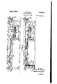
Aug. 31, 1943. J. B. SCHWAB 2,328,299
GRApING AIPARATUS QFiled Aug. 12, 1941 `5 Sheets-Sheet 1 IN VEN TOR. JOSEPH E. .S'c H wn a A' rToE/VEX J. B. SCHWAB GRADING APPARATUS 'Filed Aug. 12,l 1941 Aug. 31, 19.43.
v 5 lSheelis-Sheec 3 l A '1m/'Ewan Y, JoscPH 'San 'wam BY M h 77W n r roem: Y.
Aus- 31, 1943. J. B. SCHWAB' 2,329,299
l GRADING APPARATUS Filed Aug. 12, 1941 5 sheets-sheet 4 m .n k mw m. l n.2? m5. m nvm mw@ NM au. NY NM\ Nw, E" M .w mx E af Q A `..m\m. A A 9 A m .mv NNt m* NMNE TTORNEK AU@ 31, 1943; J. B. scHwAB GRADING APPARATUS ATTORNEY.
Patented ug. 3l, 1943 r UNITED STATES PATENT @OFFICE `2`,32:`;,299-"`` y APPARATUS L o IosephBL schwab, stockt-encara v Appuauqnjapgggia isinfsoriaiivq. 406,503`- i (Chaos-.125i- My invention Vrelates to grading apparatus and more particularlyto graders of the endless-,belt
type for enabling workmen Yto classify objects to be graded, and whichisfprovidedjwithmeans to distribute `the classified objects to desired locations where they may becollected lin receptacles.
applicability for the grading of potatoes Howf jever, it will;` be` apparent, as" thespecification prof.
occupies a minimum space`,.has;a large capacity Y ...'Iheapparatusoflmy invention has` found 'great "proved apparatus of the characterqdescribed, i
" which is of` simple and(economical.construction,
even though` occupying v:a minimum-space and which is of such construction as to enableworkmen to classify quickly ,and easilypthe.objects` to "-be graded. fOtherwobjects of `my invention will V'become apparenti from a'perusalofY the follow-` ingdescription thereof.`
` In general, `the apparatus of lmy invention com-` ,prises a plurality of v:adjacent 'main endlessconareye1fs'whicl-1 are positioned side by side in spaced relationship. .The upper reachesof `such conf "zv'eyers conduct the objects to;,be classied in one. direction; .and workmen at the sides of suchlcon-` ,veyers can readily select objects from the upper Areaches and place them iny suitable "object "receiving means in the spaceibetween ,the conveyers.
beingshqwn brokenaway toshorten thefview';l
FigLG isa section taken in planesindicated by line {if-6in. Fig. `1; portions of the structure be-` l ing omitted to shorten th'e View; v
Fig. 7 is a sectional View1 taken in a cated by line l--lin Figl. Such section line 1 1 y appearsat twodocations; the View being `thesarne ateach of such locations; v Fig. 8 is a sectiontalrenv in a plane indicated `by lined-8 in Figi; .A
. vFigQQisl asection taken in a plane" indicated bylineB-fQinFigl; 1 f l. 10 is a section taken in a plane indicated by linefhID--lll in Fig.`1;" p Y f Fig. 11 `isa section taken in a by1ine"Il,-`-`I|`in1iig.-i1;
Fig. 12 is a perspective View of a distributing deector employed on the machine;`
piane'findiad i Fig. 13 is a more or less `schematic plan View illustrating` drivingmechanism for the apparafk tus; portions of the structure being omitted from the viewtoillustrate moreclearly the construction;y y m .,Fig. 14 is anend elevation oi a desirable form of receptacle' supporting mechanism thatjmay be.
employed with the apparatus, looking in the direction ofarrow I4 in Fig. l;
.. Fig. l5 `is a side.` evation of the structure ap@ peering inFigflA, looking in the direction of arrow l5inEig.14;a portion of the structure beingshown `in'secticn to illustrate more clearlydirection opposite-to the yupper reaches, `convey p p the objects to the cross conveyor. which has means enabling proper segregationgof` the classified objects which areco'nducted Atopredeter` mined locations. Objects remaining on theiupperreaches of the adjacent main .conveyers are `collected at the discharge` `turns thereof;
Reference is` nowmade to the drawings for more detailed description*` of the r invention, in`
of the apparatus of.7
vtaken in planes indicatedby line 4-44 in Figu2; i
` Fig. 5 is a section taken inafplane indicated by line -5-5 in" i Fig. 1 ;v `a portion" "of "the structure the construction.`
The preferred farmaciy grading `apparatus`,' .which is` illustrated,..cornprises a pair of adjaf cent endless beltconveyers Zand 3` which are substantially the same length and are positioned side` by side with `a space therebetween.` The turnsrof such` conveyors are about rollers 4; and upperjreach 6 of conveyer 2 travels in' one direction, `which is `the Ysame astheupper reach" 'i of conversyerl,` while the lower reach Bf of `conveyer \2and the lower reach 'l'` ofconveyen 3 travel inan'opposite direction. Such directions of `travel are indicated by the direction arrows in the drawings. Idler rollers 8 are provided at i suitablygspaced distances along` the various reaches to'support thesame.
As can be seen more clearly from Figs. 2 and 3,2the lower reaches 6 and l have portions 9 about intermediate guide `rollers Il which are so positioned-as to provide arelatively large space |2f adapted "to receive,`under theupper reaches 6 and 'l and without interference to the travel of the lower reaches,.a cross conveyor I3 for a purpose `to be subsequentlygexplained. In this turn of'pre-gradingfconveyer IT.
`connection the upper left hand guide'. roller II,
appearing in Figs. 2 andl 3,:prcvides intermediate f discharge turns on lower reaches 6 and l', ad-
jacent conveyor I3. The entire assembly, v including rollers 4, 3 and H, is supported on' a suitable frame structure Ill; the right hand. roller 4 appearing in Figs. 1, 2 and 3 being mounted i Any suit# are usuallyvassociated with any suitable washing means (not shown) andpre-grading mechanism bylwhich the potatoes are first washed, and then the smaller sizes thereof segregated., A portion of the last' pre-grading mechanism, Which may comprisean endless apertured conveyor Il, 'in
which the apertures arev of va size suicientjto f pass only. a desired' small size potato, is shown associated withendless conveyors 2 and 3, at the kreceiving turnsthereof appearingat the right in l Figs. l, 2 and 3. v Suchpre-grading conveyor 'de-y A livers various sise "potatoes ontor the upper 'reaches S and 'i of'conveyers 2 and 3. Eor example, the potatoes delivered maybe relatively large size baking'potatoes, a select size, a size designated in the .Mart as twos and relatively poor potatoes designated as sulla `Means. is provided between pre-grading con veyerlr andy endless conveyors 2 and Sto insure uniform distribution of the potatoes on such coriveyers.v Such means comprises a cleiic-:ctorV IB mounted for lateral adjustment in thefspace between endless conveyers'z and 3 adjacent the receiving turns thereof. The deilector includes opposite side walls I9 which slope downwardly and outwardly' from a central dividing baiiie 2|, and is formed atoneend with a recess 22 of a proper curvature to accommodate the discharge At its opposite end 23, deilector vI8 has stud 24`which extends through elongated'slot 26` formed in upwardly extending bracket member 21 secured to frame vstructure 'i12 and aiwing nut 28 screwed on stud 2d serves to hold deflector I8 in laterally ad- .justedposition Should the vovv. of potatoes be unequal to the upper reachesll anclf'i of endless conveyors 2 and 3,' respectively, deflector I8 may be readilyadjusted laterally'between the two conveyors to the point where the dow of potatoes is so divided as to cause uniform distribution thereof on such upper reaches B and l.
is the potatoes are carried infone direction bythe upper reaches '6 `and 'I'of oonveyersZ and il, respectively, workmen who are positionedV at the side of, such conveyors can readily make a .iurther'grading of the potatoes by removing from such upper reaches potatoes of desiredl characteristics; and to expedite the grading operation, means is provided inthe space between conveyors 2 and' 3 for receiving the ypotatoes,selected 'by the workmen. Such means lcon'iprises a plu ralityr of hopper-like openings S5, 31, 38, SS'and di, which are 'formed between spaced walls 42 in the srrace'betwecnconveyors 2 and 3 and which f extend above the upper-"reaches of such' conveyers along theinadjacent inner side edges; similar' walls i3 extending adjacent the outer side edges of suchconveyors'.v Thus-the pairs of walls 152 and form troughs 44' in vvl'iicloy potatoes conducted by the upper reaches ofthe conveyors are'retained.` v
The topA spaces adjacent openings 35, 31, 38,
39 and lI arev closed bysuitable covers 46; and
- the upper reaches of conveyers 2 and 3.
the potatoes will' contain a large number of a suitableend Walls Il'I between side Walls 42 coopcrate-with such side walls to segregate completely the openings. Hence, potatoes deposited in the openings will fall downwardly therethrough by gravity.` Each of the potato-receiving openings is intended to receive potatoes of predetermined e characteristics selected by the workmen; and to indicate thel type of potatoes which the openings are adapted to receive, suitable designations may ybe 'imprinted on the apparatus adjacent such openings.- The vopenings may be of` any predetermined size according to the proportion of the various grades of potatoes being conducted by Usually,
so-called two grade, and a smaller number of sol-called ycolis and bakers Hence central 'opening 38, which is the largest opening, is adapt; ed to.. receive "twos; relatively small opening 3l at the left of opening 38 (as the openings appear in Figs. 1, 2 and 3) 'is adaptedto `receive culls; opening at the left of opening 3'I`is adapted to receive tw'os which may notl have been selected at the time theylpa'ss opening 38; opening 39 at the right ofopening 38 is adapted to receivev "cullsi and openingwII at the right `of opening 33 lisy adapted 'to receive "bakers. In this connection, itis to be observed that segregation between-openings 39 and 4I is'bymeans of vertical partition Wall l 48 extending between spaced walls 42.v Workmen leave `ontlie upper reaches 6 and 'I `of the` conveyors, aselectgrade of potatoes which'are Ayconducted to a seeking station A` at theidischarge' turns, where they are sacked byy anyfsuitable means, a preferred form of which is illustrated andY will be subsequently described. v Means, includingthe andv I of conveyersfZ and .3,..respect'ively,is associated with the potato-receiving openingsiior conducting selectedk potatoes to predetermined locations onendless cross conveyor 53,1Where they may be also sacked. l-Aswas previously related, cross conveyor I3 is lmounted inrelatively .large space l2; and onej-sidefthereof is adjacent l'the intermediate. discharge.- turns .on the.' under reaches 6 and'' formed bythe left` upper guide roller II appearing in` Figs. 2 and 3.! The' side edges of conveyer`|3 are bounded by side Walls 49; 'a partition wall 5I being located over 'the upper reach of the conveyer in line with vertical partition wall I84 and another partition wall 52 being also provided over theu'pper reach of conv veyer I3 to the left of wall 5I. Thus, with particular reference to Figs. 1 and 4,'walls A9, -5I land 52 cooperate with conveyor I3 to provide a left trough 53, yan intermediate trough 5d, and a'righttrough 53 which are adapted to segregate the potatoes and convey'the'm in independent paths. Y I y Left trough 53 is adapted to receive potatoes from lower reachy 'I' of conveyer 3 and intermediate trough 54 is adapted to receive potatoes from the'lowerreach 3 of conveyor 2; a diagonally positioned partition 5'! extending over conveyor-13 from an end of partition wall 52 to a position between reaches 6 and I to segregate the potatoes as they are delivered onto conveyor I3 by lowerreaches 6 and 'I'.` It is to be noted that the space over conveyor I3 between diagonal I lower or return reaches Ii j d 2,328,299 Iltis.in communication'with trough 56 so that "bakers deposited thereincwill be delivered into trough 56 to a suitable' sacking station C;`` an oblique end `deilector 58 being` positionedl over conveyei" I3 inassociationfwith trough 56"to deliverthe potatoes `sidevvise `to sacking: station C.
z With referencetoFig 8, it is to be noted that wallw42 adjacent the `inner `edge ofccnveyer'" 2 is :formed `wtih a side aperture 59 in communication with lower` reach 6", `and. that hopper opening 31 is provided with an inclined `bottom 61T to..deliv`er `by gravity the f culls deposited thereinthroughaperture 59 ontozthe lower reach 6'. ofconveyer` 2.` "Ihus, 'culls vdeposited 'in opening 31 are l directedfto the lower reach, 6,' of conveyor 2l `where ythey are carried back `by such reach 6 to `Athe spacepover conveyer I3Rbetween diagonal'partition51 and `wall 5I, so that such zculls. intermingle with the .culls depositedr in opening 39. i
i Each ofopenings 36 and 38 delivers twos to lower reach 1` of conveyer3 which conducts such "twos to trough. 53 on'conveyer13 where 4they are carried to sacking station D; asutable oblique end `deilector 62 `being Vprovided over conveyerr `I3 `in` association with trough 53.to deliver` the ,twosf `sidewise to sacking station D. Themeans vfor delivering the potatoes t'o `lower reach 1'. of
taken attwo locations. Such delivery `means comprises an inclined bottom 63 for `eachof openings` 36` and 38, which conducts the lpotatoes by Ygravitywthrough an aperture 64-formed in wall 42 adjacent the inner edge of conveyer, onto the lower reachJ of such conveyer3.` t
From the preceding description it isseen that the `upper conveyer reaches 6, and `1 traveling in one direction conduct `a select grade of potatoes left thereon to sacking station A1; `lower cured thereto rollers 82 slidably mounted in a" conveyer reach 1', traveling in an opposite li-` rection, delivers "twos deposited in openings 36A and 38, into troughj53 where they are conducted to sacking station D: lower reach 6'.. also traveling in -adirection opposite to `that of the' upper reaches,;conducts culls` deposited in opening 31, into intermediate trough y54on conveyer I3, and cul1s'" alsodeposited in opening 39 are delivered into trough 54 where `the ,culls"are `conducted to sacking stationB; and bakers` deposited in opening IIfall intotrough 56, where `they are conducted to sackingstation C. `Thus a compact-arrangement obtains by virtue4 of the adjacent main conveyers.` the utilization of the lower reaches of such conveyers ivorreturning thefgraded potatoes, andthe `cross,conveyer I3 for conducting such `potatoes to suitablesacking locations. d 1 I- v Any suitable means may be provided for driving conveyers 2, 3and I3 at suitable correlated speeds. A form of `such` means is schematically illustrated in Fig. 13, .comprising `driving chain 61, connectedto any suitable power source not `shown and adapted to rotate sprocket-68con `nected to drive roller` t formingthe receiving turns for conveyers 2 and 3., VDriven `from chain 61 is a downwardly extending chaindrive 69 connected to drive crossshafting 1|`` in turnconnected by bevel gearing 12 to upwardly extending chain` drive 13 which is. connected,to shaft` `14 which drives chain drive 16 connected to a `driving roller 11 formingone oftheturns of conveyer I3.` The drive is such as to cause the upperreaches of conveyers 2 and 3 to travel to the left with reference to Figs. 1 and 13; and to cause the upper `,reach 'ofconveyer I 3tor travel in a proper directiontowardstations B, Cand `D, suitable reversegearing in box 1I! isinter- `posed in cross shafting 1I, in the 'form `of drive illustrated.- H
Although :cross `conveyerI3 is illustrated las extending beyond :the 1 left v side .of` main c'onveyer 3 with referencexto the directionlof travel'ofy the upper reach thereof, it is apparent thatzsuch cross conveyer including its segregating troughs, and the drive therefor, maybe assembled so as d to extend beyond ,the right` side ofconveyer 2 if so desired. This feature isfdesirablefbecause,
depending` upon theground floor arrangements that may exist in various plants, itmay bemoreconvenient to have cross ,conveyer I3 adapted` for extensionfrom either side of the main conveyers.l
`Any suitable"receptacle means may be` .pro-1 vided at stations A,B,,C,and D for sacking of the graded potatoes. With referencei to Figs. 14 andl5, I prefer to employfa novel form of `sacking `means which enables onesack or re-` ceptacle to` be ,in position for receiving graded potatoes while another sack adjacent thereto Acan be prepared to receive such potatoes, so that when such sack is loaded, the other sack can be shifted to a` position for` loading thereof` without interruption ofthe flow of potatoes. Such sacking means is the same at allot the stations; therefore, only themeans at` station A will be .described- 1` Adjacent the discharge turnof each of theconf veyersl` or 3 is a sackingframe 8| having secross-rail 83 secured `to framestructure I4, sol
as to permit `shiftinglof the frame relative' to such conveyer. Rollers82 support the weight of sacking frame `8I and cooperating lower` rollers B4 bearing against alower cross-rail 86, also supported on framework I4, maintain the sacker in an` upright position..` Frame 8`I ,hasf apair` of i pivotally mounted, rectangularly shaped' open sack supporting brackets ,81 positioned sideby 1 side, andhaving corner hooks, upon which a `fabric: sack may be removablyattached. With one'of sack supporting brackets 81 having a sack thereon, in a. position to be filled, the other adjacent sack supportingmbracket 81 is out of such position, and a sack/may be readily attached thereto. j 1 d l `When a sack being vloaded is completely filled, the entire frame `may be rapidly shifted end- `wise" so that `the other `prepared sack may be filled without interruption in `the ow of Dotatoes." The filled sack maybe readily removed andan empty sack replaced in positiontherefor.i
Thus itis seen that no time will be lost during the sacking. The pivotal mounting of the' sacksupporting brackets 81 is-desirable because it permits manual up and down movement while1 asaok is being loadedto` cause the load to fill;`
evenly such sack. Also, `such mounting allows the brackets` to be` raisedV when nit is desired to attach `or disconnect a sack therefrom, thus, `fdacilitating suchoperations.
The widthof `endlessconveyers 2 and 3. is. greater than the width of each of sack sup-poiftf` ing brackets 81; and l-to cause the potatoes to ow in a proper stream into the sacks and yet allow plenty of roornfor shifting of both ofthe, sacking frames BI at the discharge turns of conveyers 2 and 3, a pair of spalcedheflectorsy 89 forming a space substantially thesame width asf each bracket 81,is associated with the discharge turn oreach of endless conveyers 2" and 3. `A
Priority Applications (1)
| Application Number | Priority Date | Filing Date | Title |
|---|---|---|---|
| US406508A US2328299A (en) | 1941-08-12 | 1941-08-12 | Grading apparatus |
Applications Claiming Priority (1)
| Application Number | Priority Date | Filing Date | Title |
|---|---|---|---|
| US406508A US2328299A (en) | 1941-08-12 | 1941-08-12 | Grading apparatus |
Publications (1)
| Publication Number | Publication Date |
|---|---|
| US2328299A true US2328299A (en) | 1943-08-31 |
Family
ID=23608281
Family Applications (1)
| Application Number | Title | Priority Date | Filing Date |
|---|---|---|---|
| US406508A Expired - Lifetime US2328299A (en) | 1941-08-12 | 1941-08-12 | Grading apparatus |
Country Status (1)
| Country | Link |
|---|---|
| US (1) | US2328299A (en) |
Cited By (4)
| Publication number | Priority date | Publication date | Assignee | Title |
|---|---|---|---|---|
| US2608284A (en) * | 1946-04-11 | 1952-08-26 | Shellmar Products Corp | Conveyer apparatus for handling and packaging eggs |
| US2793747A (en) * | 1955-10-24 | 1957-05-28 | Whetstine B Pridy | Debris and potato sorting device |
| US3595389A (en) * | 1970-03-05 | 1971-07-27 | George W Morgan | Reclamation method and apparatus |
| US5263591A (en) * | 1991-12-12 | 1993-11-23 | Taormina Industries, Inc. | Refuse recycling system |
-
1941
- 1941-08-12 US US406508A patent/US2328299A/en not_active Expired - Lifetime
Cited By (4)
| Publication number | Priority date | Publication date | Assignee | Title |
|---|---|---|---|---|
| US2608284A (en) * | 1946-04-11 | 1952-08-26 | Shellmar Products Corp | Conveyer apparatus for handling and packaging eggs |
| US2793747A (en) * | 1955-10-24 | 1957-05-28 | Whetstine B Pridy | Debris and potato sorting device |
| US3595389A (en) * | 1970-03-05 | 1971-07-27 | George W Morgan | Reclamation method and apparatus |
| US5263591A (en) * | 1991-12-12 | 1993-11-23 | Taormina Industries, Inc. | Refuse recycling system |
Similar Documents
| Publication | Publication Date | Title |
|---|---|---|
| US3837469A (en) | Product orienting apparatus for packaging | |
| US1958322A (en) | Conveyer or screening apparatus | |
| US2328299A (en) | Grading apparatus | |
| US2003097A (en) | Fruit sizer | |
| US2886173A (en) | Egg processing plant | |
| US2878776A (en) | Apparatus for coating and conveying doughnuts | |
| US1880284A (en) | Conveyer | |
| US2367757A (en) | Fruit feeding device | |
| US2420941A (en) | Combined picking table and screen of the drag-conveyor type | |
| US2315013A (en) | Sorting table | |
| US2313051A (en) | Fruit handling equipment | |
| US1609442A (en) | Potato and onion grader | |
| US1890762A (en) | Conveying apparatus | |
| US1358061A (en) | Fruit-grading machine | |
| US4379055A (en) | Apparatus for the drip dry conveyance of oil-fried dough products | |
| US1920701A (en) | Potato sorter | |
| US2209268A (en) | Stone picker for self-feeders of threshing machines | |
| US1147283A (en) | Pea-grader. | |
| US1431667A (en) | johnson | |
| US2442521A (en) | Machine for conveying and assorting fruit according to weight | |
| US2071456A (en) | Domestic screening plant and bin arrangement for coal | |
| DE1929442A1 (en) | Method and device for filling containers | |
| US2517341A (en) | Adjustable range egg-sorting machine | |
| US2849913A (en) | Egg feeding and candling machines | |
| US1705456A (en) | Coal and rock separating mechanism |