US2315336A - Heat power plant - Google Patents
Heat power plant Download PDFInfo
- Publication number
- US2315336A US2315336A US270082A US27008239A US2315336A US 2315336 A US2315336 A US 2315336A US 270082 A US270082 A US 270082A US 27008239 A US27008239 A US 27008239A US 2315336 A US2315336 A US 2315336A
- Authority
- US
- United States
- Prior art keywords
- container
- substance
- combustion
- chamber
- receptacle
- Prior art date
- Legal status (The legal status is an assumption and is not a legal conclusion. Google has not performed a legal analysis and makes no representation as to the accuracy of the status listed.)
- Expired - Lifetime
Links
Images


Classifications
-
- F—MECHANICAL ENGINEERING; LIGHTING; HEATING; WEAPONS; BLASTING
- F02—COMBUSTION ENGINES; HOT-GAS OR COMBUSTION-PRODUCT ENGINE PLANTS
- F02C—GAS-TURBINE PLANTS; AIR INTAKES FOR JET-PROPULSION PLANTS; CONTROLLING FUEL SUPPLY IN AIR-BREATHING JET-PROPULSION PLANTS
- F02C5/00—Gas-turbine plants characterised by the working fluid being generated by intermittent combustion
- F02C5/12—Gas-turbine plants characterised by the working fluid being generated by intermittent combustion the combustion chambers having inlet or outlet valves, e.g. Holzwarth gas-turbine plants
Definitions
- Figs. 15, 16, represent the container VB, together with its valves, and show the position of the valves in succession during the transition from the heat absorption to the period of expansion in the case where combustion is still to take place during expansion.
Landscapes
- Engineering & Computer Science (AREA)
- Chemical & Material Sciences (AREA)
- Combustion & Propulsion (AREA)
- Mechanical Engineering (AREA)
- General Engineering & Computer Science (AREA)
- Fluidized-Bed Combustion And Resonant Combustion (AREA)
Description
M361. 30, 1943. w, KAR-RER TAL 2,315,336
HEAT POWER PLANT Filed April 26, 1939 5 Sheets-Sheet 1 1! v WrnerKarre)? flan gois z err'enoud,
INVENTORS 2; ATTO EY March 30, 1943. w. KARRER ETA!- HEAT POWER PLANT 5 Sheejts-Sheet 3 Filed- April 26, 1939 )Vrn er" Karref:
za- 1d mac az'sPerrenoud,
INVENTORS,
M y ATTOR EY Mam]! w. KARRER ET AL 2,315,336
' HEAT POWER PLANT Filed April 26, 1939 5 Sheets-Sheet 4 7 1r A! z e 1 15mm 6 m M M k 2 LL i 1d, 'II &% 2%] (EH 3 a r'x (gale i I I a I i i L 11 I" l 50 w l I iI Zrner K'arrer fiangazlsj ermnouafi INVENTORS,
7 ATTORNE March 30, 1943. w K E f- 2,315,336
HEAT POWER PLANT Filed Apri1 26, 1939 5 Sheets- Sheet 5 I IIIIIIIIIIIII. IIIIIIIIII/IIIIIIIIIA INVENTORS, iVrner Karrez; Franaais Perrenoud,
ATTORNEY Patented Mar. 30, 1943 HEAT POWER PLANT Werner Karrer and Francois Perrenoud, Zurich,
Switzerland,
assignors to Maschinenfabrik Oerlikon, Oerlikon, Switzerland, a corporation of Switzerland Application April 26, 1939, Serial No. 270,082 In Switzerland April 30, 1938 22 Claims.
In a combustion product power plant which is operated by heat being supplied to a working substance at constant volume before it performs work in the prime mover, and withdrawn under constant pressure after it has performed work in the prime mover, while at least part of the heat withdrawn under constant pressure is employed to furnish part of the heat supplied at constant volume, combustion may be provided for after preheating at constant volume.
The idea to effect combustion by steps, for example by igniting again at the end of each period of preheating, produces all the drawbacks of a periodically working ignition device and brings about a sudden rise in pressure, which stresses the materials to their detriment. To obtain therefore as uniform and as good a combustion as possible, the invention makes use of mechanically precompressed fresh air, the precompression pressure drop of which is converted again into mechanical work in a special gas turbine, and said air, after being preheated in the constant volume chamber closed to the outside, that is to say, in the space in which the rise in pressure takes place by means of exchange heating, is burned in a combustion chamber which is connected to and communicates with at least a part of the constant volume chamber and in which there is maintained at least at one point a temperature above the ignition temperature of the fuel-air mixture so as to insure the ignition thereby of the fuel-air mixture that is introduced. The temperature above the ignition temperature may be maintained by means of one or several burning flames, by sparks, ignition bodies, ignition wires and the like. In the case of certain connecting systems a flame burning constantly while the power producing elements continue operating under load may be utilized.
The annexed drawings show diagrammatical examples of embodiments of the subject matter of the present invention.
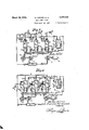
Fig. 1 is a diagrammatic layout showing a heat power plant constituting the invention, and illustrating one of the phases in the alternate operation of its power producing medium containers.
Figs. 2 and 3 are views similar to that shown in Fig. 1, but illustrating the remaining phases of said operation.
Figs. 4, 5, 6 are diagrammatic layouts showing a heat power plant which is a modification of the invention, but illustrating it with three different modes of utilizing its combustion period.
Figs. 7 and 8 are diagrammatic layouts showing heat power plants constituting other modifications of the invention.
Fig. 9 is a cross-sectional elevation, showing a modified form of the combustion chamber of the invention.
a Fig. 10 shows a transverse-sectional bottom plan view of the combustion chamber in Fig. 9, taken on line ill-I0 thereof.
Fig. 11 is a cross-sectional elevation, showing a modified. form of the heat exchanger of the invention.
Fig. 12 shows a transverse-sectional bottom plan view of the heat exchanger in Fig. 11, taken on line l2-i2 thereof.
Fig. 13 is a cross-sectional elevation, showing another modification oi the combustion chamber of the invention.
Fig. 14 shows a transverse-sectional bottom plan view of the combustion chamber in Fig. 13, taken on line l4-l4 thereof.
Figs. 15 and 16 are fragmentary diagrammatic layouts showing the power plant in difierent phases.
In the diagram of Figs. 1 to 3, several containers V13 V3 V13 are provided for the exchange heating on the counter current principle, which containers are filled, heated and emptied alternately in succession and are connected to communicate with each other in each heating period with the chamber VA of the exchanger I, forming each together with VA the constant volume chamber.
In the first place, the container VB is in the scavenging and filling period (Fig. 1). A compressor 4 then conveys fresh air into the container VB through pipe a across the valve la. and simultaneously scavenges, through the valve lb and the pipe I), the remaining hot air from the container V31 to the collecting chamber 1. After the container VB has been filled, the valves Ia and to are closed and the valves Id and le opened (Fig. 2), the fresh air being new conveyed by means of a blower 8 through the valve Ie and the pipe e to the chamber VA of the exchanger and thence returned through the pipe at to the valve Id and the container vB As heat is absorbed in the exchanger division VA at the constant volume VA an V13 an increase in temperature and pressure results in the constant volume VA and Va Following the preheating by supplying heat to the chamber VA, an additional supply of heat by the burning of the fuel-air in a combustion chamber is now to take place. This supplying of heat may take place either during the preheating, or after the termination of the heat supply by exchange preheating, i. e., after closing the valves Id and le, or in the subsequent expansion period. The spatial arrangement of the combustion chamber is provided for in a different manner, depending on the period in which combustion is to take place, as will be hereinafter shown.
the valves id and le are closed and, following this or perhaps after the expiration of an interposed combustion period, the valve la is opened (Fig. 3), whereupon the products of combustion empty by way of conduit into the prime mover 5, which may be a gas turbine for example, and perform expansion work therein. The waste gases of the turbine reach for example the collecting chamber I, where they encounter the scavenge gases flowing through the pipe I), which gases come from the container which at the moment is in the period of scavenging and filling. (In Fig. 3 from the container V13 chamber 1 the Waste gases of the turbine 5 together with the scavenge gases of the container just being scavenged, reach the gas turbine 6 by way of conduit 1, where they perform additional work, and finally fiow through the chamber Vo of the exchanger 1, where they give oif part of the residual heat to the division VA of the constant volume space. Finally the waste gases escape through the pipe g. The turbines 5 and 6 drive for example the compressor 4 and the generator 9.
In the containers V3 Ve V13 the periods of filling, heat absorption at constant volume and evacuation alternate. Fig. 1 represents the period in which Va is being scavenged and filled, V3 is connected to the exchanger for the purpose of absorbing heat, and expansion takes place in V3,.
Figs. 2 and 3 show the other two phases.
Whereas it is only indicated in Figs. 1 to 3 that a combustion chamber B1, B2, B3 communicates with each container V13 V13 V12 Figs. 4, 5 and 6 show sections of a plant according to Fig. l, which represent special arrangements of the combustion chambers B1, B2, or B3 communicating with the containers vB V13 or V3 In Fig. 4 the combustion chambers B1, B2, B3 are located in the lines r1, r2, in, through which flows the preheated air coming from the exchange chamber VA through pipe (1 during the heat absorption period in which the appropriate valves Id and le, or 2:1 and 2e, or 3d and 3e are open. In Fig. 4 the container Via is in the heat absorption period, as in Fig. 1, the valves 2d and 2e being therefore open, while the container V13 is scavenged through the valve lb and filled from a with precompressed fresh air. Expansion takes place in VB by way of c. Therefore, the constant volume chamber, during the period represented in Fig. 4, consists of the appropriate connecting pipes and the container VB. the exchanger division VA and the combustion chamber B2. The mechanically precompressed air which is in V13 from the filling period is returned, by means of the blower 8, from VB across the open valve 2c, the pipe e, the exchanger chamber VA (which may consist of the interior of a nest of tubes), the pipe (I and the open valve 2:1 to the combustion chamber B2 and thence in the form of gas with any desired excess of air to the container V3 During this operation the air is preheated in VA and at least partly burned in B2. When the container VB has been filled up with sufficient air which has been thus conveyed, heated, and burned in this circulation, the valves 2d and 2e areclosed, and the contents of VB2 which has undergone an increase in temperature and pressure through heat absorption in VA and combustion in B2, is ready for expansion. There then follows for the container V13 the period of expansion, while VB enters the heat absorption From the collecting period. The action of the various periods is repeated, as was described with reference to Figs. 1 to 3.
Fig. 5 shows another position of the combustion chambers B1, B2, B3 which, though communicating again with the containers V13 V13 V13 are situated in the pipe line sections s1, s2, 83, through which flow, in each period of expansion, the gases which flow through the valves [0 (or 20, 3c respectively) and the pipe 0 to the turbine 5. Fig. 5 represents the same period shown in Fig. 1 and Fig. 4. Expansion takes place in the container Ve which has been pre heated, as seen in Fig. 3, by being connected to VA and by the circulation of the air content, with the chamber closed to the outside. The air flows through the combustion chambr B: only during expansion, and burns there at least partly before it is admitted to the turbine 5 across the open valve 30 and the pipe 0. Therefore, in this arrangement combustion occurs not before the expansion period.
In Fig. 6 the combustion chambers B1, B2, B3, which again communicate with V3 V13 and V33 respectively, are located in a section of line limi or l2m2, Isms forming the common supply pipe to the valves Ic, Id or 20, 2d or 3c, 3d. It will be readily observed that in this arrangement the combustion chambers carry a stream of fluid both during the heat absorption period and in the expansion period. As Fig. 6 represents again the same condition of time as Figs. 1, 4 and 5, the container VB is in the period of heat absorption, i. e., the air is conveyed, by means of the blower B, through the valve 2e, the pipe 6, the exchanger chamber VA, the pipe d and the valve 211 to the combustion chamber B2 and partly burned there, to be returned to the container V13 in the form of a gas with an abundant excess of air. Such partly burned gas is present in VB, from the preceding period, which in the period represented now flows through the combustion chamber B3, the valve 30 and the pipe 0 to the turbine 5, where it performs work. In the combustion chamber B3 additional portions of air are burned, the excess of air on entering the turbine 5 being thus smaller than when leaving V3,. The cycle of the various periods of scavenging and filling, of absorbing heat during the circulation through the exchanger and the combustion chamber, and of expansion through the combustion chamber and turbine again occurs as described with reference to Figs. 1 to 3. In the heat absorption period a rise in pressure and temperature takes place in consequence of heat being supplied to a chamber closed to the outside.
Since the combustion chambers B1, B2, B3 remain in communication with the proper container V13 V13 V13 care must be taken that no substantial amounts of fresh air are burned during the non-appropriate time of combustion, especially during the period in which the chambers VB are filled with fresh air (from the pipe a). This may be eifected by throttling the fuel supply, by means of any usual devices or valves 32, in lines it leading to the combustion chambers. In Figs. 4, 5, 6, moreover, the fresh air supply is so conducted that the fresh air does not flow through the combustion chamber. In combustion chambers B1, B2, B3 there is maintained simultaneously a temperature above the temperature of ignition of the fuel-air mixture by means of one or several flames, sparks, ignition bodies, ignition wires and the like, for the fuel-air mixture to be ignited thereby, as indicated by ignition plates 3 I, Figs. 1 to 6.
Of course, during the period of combustion the fuel supply must always be raised to the nominal value, with the result that a periodically variable fuel supply is established. This mode of operation is changed by the second arrangement described in the following lines and is an improvement because the operation may be carried out with constant flames.
Such an arrangement is shown in Fig. '7, where the combustion chamber B is located on the exchanger side of the valves Id, 2d, 3d, 1. e., directly in series with the exchanger part VA. Therefore, only one combustion chamber need be provided, and is connected together with the chamber VA successively alternately to the various chambers VB by actuating the valves id, or 2d, or 3d and 16, or 2e, or 36, the valves Id and is each being open only in the preheating period (which in this case is simultaneously the combustion period) of the containerVB the valves 2d and 26 in that of the container V132, and the valves 3d, 3e in that of the container VH3. Fig. '7
represents the same state as in Figs. 1, 4, 5 and 6,
namely the period in which scavenging and filling occurs in VB1, the absorption of heat (circulation) in VB2, and expansion in VB3. The other states may be readily reconstructed.
The operations here described with reference to the container VB are the following:
After filling the chamber VB by means of the compressor 4, the pipe at and the valve Ia and simultaneously scavenging the residual gases through the valve lb and the pipe 1) into the collecting chamber 1, the valves la and lb are closed and the valves Id and le opened. By means of the blower 8, which in this case is mounted for example in the pipe line e, the fresh air is conveyed from the chamber VB through the valve l e and the pipe e to the preheating chamber VA where it takes up heat by exchange at constant volume, and then through the combustion chamber B, where the combustion takes place, to be returned to the chamber VB across the pipe d and the value Id. After circulating the desired amount of fresh air of the chamber V31, that is to say, after filling the chamber VB with the desired amount of combustion gases, the valves Id and le are closed again and the valve [0 is opened, which makes it possible for the expansion to take place in the turbine 5, the waste gases of the turbine meeting in the collecting chamber 1 with the scavenge gases from the container that is being scavenged. The further path of the gases is Q the same as described in Fig. 1.
The containers VB and VB, again cooperate with VB in such a manner that they pass alternately and successively through the periods of scavenging, heat absorption and expansion, as was described with reference to Figs. 1, 2 and 3.
During the period of heat absorption the contents of the container is circulated as before through the exchanger and the combustion chamber by means of blower 8. The constant volume chamber here consists alternately of the chambers VA+B+VB1 or VA+B+VB2 or VA+B+VB3; the spaces VA+B are in each period part of the constant volume chamber. The blower 8 operates continuously. The waste gases of the turbine 6 (which for the rest describe for example the same circuit described in Fig. l) flow continuously through chamber Va. A flow of air and. gas is also constantly present in the chambers VA and B, with the exception of the perturbations caused by switching from one chamber to the next, which makes it possible for a flame to burn continuously under load in the combustion chamber B, without having to run without load for long intervals as in the case of Fig. l. In this case it is therefore not necessary to adjust periodically the fuel supply to the combustion chamber. 7
It may often be found advantageous to give up part of the heat delivered to the chamber VA and B to a cooling chamber outside, thus not employing it for the purpose of expansion in the turbine. Particularly the delivery of heat to a steam power system is here considered, preferably by heat exchange in a boiler, superheater or feeder heater.
We must emphasize in particular the case illustrated by Fig. 8, where the cooling chamber VB together with the chamber VA and B is in each case connected to the various containers VB.
Fig. 8 differs from Fig. '7 in that the part of the constant volume chamber which is alternately connected to the various chambers VB and forms in each period part of the constant volume chamber, does not consist only of the exchanger chamber VA and the combustion chamber B, but has connected to said two chambers cooling chambers VB and VF, in which a portion of the previously delivered heat is given up to the outside, 1. e., to the chambers VE and VG- Therefore, during the period of circulation the fresh air of the container VB that may be connected is in this case circulated by means of the blower 8 successively through the chambers VA, B, VB, and VF, in order to take up exchange heat in VA, to be burned in B and to give up again part of the heat in VD and VF to VB and VG and to be returned to the chamber VB with the outlet temperature of Vr. All the chambers VA, B, VD and V]? are here collectively and alternately connected to the various chambers VB and disconnected from them. For example, in VB and VF the heat is given up to water steam, which is vaporized in VB, is superheated in VG, (boiler l0, superheater l I) is expanded in the steam turbine l2, liquefied in the condenser l3, and preheated in the feed water heater [4 by the waste gases.
Of course, any live heat sources may likewise be employed for the purpose of vaporization or superheating.
Refrigeration may also be effected in the combustion chamber itself, as indicated in Figs. 9 to 14, inclusive. Figs. 9, 10 show a combustion chamber B concentrically surrounded by the cooling chamber VE. In Figs. 11, 12, the cooling pipes V lead through the interior of the combustion chamber B, while in Figs. l3, l4, concentrically arranged cooling pipes Vs are provided around the combustion chamber B. In all these cases the maximum temperature of the combustion chamber is kept at lower values.
Therefore, the arrangement of the combustion chamber B in series with the exchanger member VA gives the result that a single combustion chamber only may be employed for several VB chambers, and that a continuous flame can be maintained in said combustion chamber without any periodical fuel adjustment, which flame must never work without load.
While in the case where the combustion chambers are designed as divisions of the container VB it is possible, by arranging their position or the pipes and valves (I c, 20, 30) leading to the turbine 5, to obtain the result that heat is delivered also during the period of expansion, Figs. 6 and '7,
the same effect can also be produced where the combustion chamber is in series with VA, by releasing the path to the turbine through opening the valve Ic (or 20, 30) before separating the chamber VA and B from the connected chamber Via (or V3,, V3 by closing the valve id and le (or 2d and 26, or 3d and 3e). Supplying heat during expansion offers the advantage that it is then possible to move th expansion from the purely adiabatic region toward the isothermal region and even toward the region of constant pressure. If a turbine is provided as the prime mover 5, it may be an advantage to supply during expansion just enough heat to insure constant speed of expansion over a maximum range of the expansion period so that the blade angles remain the most suitable with respect to the resulting speeds over this whole period of time. The early opening of the turbine valve may of course be employed for example also in the case of Fig. for the purpose of supplying additional heat.
Figs. 15, 16, represent the container VB, together with its valves, and show the position of the valves in succession during the transition from the heat absorption to the period of expansion in the case where combustion is still to take place during expansion.
Fig. shows the container VB, in the heat reception period, the valves 2d and 2e bein open, the other valves being closed.
Fig. 16 shows the container VB. in the period of expansion after closing the valves 3d and 2c, the only open valve being 20.
In all the examples a combustible gas could replace the fresh air, and an oxygen carrier could replace the fuel.
Variations may be resorted to within the scope of the invention, and portions of the improvements may be used without others.
Having thus described our invention, we claim:
1. In a combustion product power plant, the combination of a container for a working substance, a heat exchanger having a closed heat receiving receptacle, means for scavenging said container of previously burned substance therein and refilling it with a fresh charge of said working substance in a precompressed state, means to circulate said compressed substance of said container through said receptacle for preheating it, means to arrest said circulation, a combustion device for said container for additionally heating within the container said compressed substance, and means to discharge said combustibly heated contents of said container for expansion for a subsequent said scavenging and refilling of the container.
2. In a combustion product power plant, the combination of a container for a working substance, a heat exchanger having a closed heat receiving receptacle, means for scavenging said container of previously burned substance therein and refilling it with a fresh charge of said working substance, means to circulate said substance of said container through said receptacle for preheating it, means to arrest said circulation, a combustion device for said container for additionally heating within the container said substance, and means to discharge said combustibly heated contents of said container for expansion for a subsequent said scavenging and refilling of the container.
3. In a combustion product power plant, the combination of a container for a working substance, a heat exchanger having a closed heat receiving receptacle, means for scavenging said container and filling it with said substance, means to circulate said substance of said container through said receptacle for preheating it, means to arrest said circulation, a combustion device for said container for additionally heating said substance, means to discharge said combustibly heated substance of said container for expansion, a collecting chamber, means to conduct the scavenged substances from said container to said chamber, and means to conduct the contents of said chamber into said exchanger.
4. In a combustion product power plant, the combination of a container for a working substance, a heat exchanger having a closed heat receiving receptacle, means for scavenging said container and filling it with said substance, means to circulate said substance of said container through said receptacle for preheating it, means to arrest said circulation, a combustion device for said container for additionally heating said substance, means to discharge said combustibly heated contents of said container for expansion, a collecting chamber, means to conduct the scavenged substances from said container to said chamber, a prime mover driven by said discharged contents from said container, means to conduct the scavenged substances from said prime mover into said chamber, and means to discharge the contents of said chamber for expansion.
5. In a combustion product power plant, the combination of a container for a working substance, a heat exchanger having a closed heat receiving receptacle, means for scavenging said container of previously burned substance therein and refilling it with a fresh charge of said working substance, means to circulate said substance of said container through said receptacle for preheating it, means to arrest said circulation, a combustion device for said container for additionally heating within the container said substance, means to discharge said combustibly heated substance from said container for expansion for a subsequent said scavenging and refilling of the container, a collecting chamber, means to conduct the scavenged substance from said container to said chamber, and a prime mover driven by the contents of said chamber.
6. In a combustion product power plant, the combination of a container for a Working substance, a heat exchanger having a closed heat receiving receptacle, means for scavenging said container and filling it with said substance, means to circulate said substance of said container through said receptacle for preheating it, means to arrest said circulation, a combustion device for said container for additionally heating said substance, means to discharge said combustibly heated substance from said container for expansion, a collecting chamber, means to conduct the scavenged substance from said container into said chamber, and a prime mover driven by the contents of said chamber and exhausting into said exchanger.
'7. In a combustion product power plant, the combination of a plurality of containers for a working substance, a heat exchanger having a closed heat receiving receptacle, means for alternately scavenging each of said containers of previously burned substanc therein and refilling it with a fresh charge of said working substance in a precompressed state, means to alternately circulate said precompressed substance from each of said containers through said receptacle for preheating it, means to alternately arrest said circulation, a combustion device for each of said containers for additionally heating within the containers said precompressed substance, and means to alternately discharge said combustibly heated contents of each of said containers for expansion for a subsequent said scavening and refilling of the container.
8. In a combustion product power plant, the combination of a plurality of containers for a working substance, a heat exchanger having a closed heat receiving receptacle, means for alternately scavenging each of said containers of previously burned substance therein and refilling it with a fresh charge of said working substance, means to alternately circulate said substance from each of said containers through said receptacle for preheating it, means to alternately arrest said circulation, a combustion device for each of said containers for additionally heating within the container said substance, and means to alternately discharge said combustibly heated contents of each of said containers for expansion for a subsequent said scavenging and refilling of the container.
9. In a combustion product power plant, the combination of a container for a working substance, a heat exchanger having a closed heat receiving receptacle, a conduit leading from said container to said receptacle, a return conduit leading from said receptacle to said container,
- means for scavenging said container and filling it with said substance, means to circulate said substance from said container through said conduits and receptacle for preheating it, means to arrest said circulation, a combustion device for said container located in said return conduit for additionally heating said substance, and means to discharge said combustibly heated contents of said container for expansion.
10. In a combustion product power plant, the combination of a container for a working substance, a heat exchanger having a closed heat receiving receptacle, a conduit leading from said container to said receptacle, a return conduit leading from said receptacle to said container, means -for scavenging said container of previously burned substance therein and refilling it with a fresh charge, of said working substance, means to circulate said substance from said container throughsaid conduits and receptacle for preheating it, means to arrest said circulation, a conduit for discharging said preheated contents of said container 'for expansion for a subsequent said scavenging and refilling of the container, and a combustion device located in said discharging conduit for additionally heating said discharging contents.
11. In a combustion product power plant, the
combination of acon-tainer for a working substance, a heat exchanger having a closed heat receiving receptacle, a conduit leading from said v container to said receptacle, a return conduit leading from said receptacle to said container,
means for scavenging said container and filling it withsaid substance, means to circulate said substance from said container through said conduits and receptacle for preheating it, means to arrest said circulation, a conduit for discharging the contents of said container for expansion, and a combustion device for additionally heating said contents being so connected to said return conduit and to said discharging conduit that it will function during said circulation and during said discharge of said contents.
12. In a combustion product power plant, the combination of a plurality of containers for a working substance, a heat exchanger having a closed heat receiving receptacle, a conduit for each of said containers leading therefrom to said receptacle, a return conduit for each of said containers leading thereto from said receptacle, means for alternately scavenging each of Said containers and filling it with said substance, means to alternately circulate said substance from each of said containers through said conduits and receptacle for preheating it, means to alternately arrest said circulation, a combustion device in a conduit leading from said receptacle to each of said return conduits for additionally heating said substances in each of said containers during said circulations, and means to alternately discharge said combustibly heated contents of each of said containers for expansion.
13. In a combustion product power plant, the combination of a plurality of containers for a working substance, a heat exchanger having a closed heat receiving receptacle, a conduit for each of said containers leading therefrom to said vice including a continuously functioning heated body for maintaining said substances thereat in continuous combustion, and means to alternately discharge said combustibly heated contents of each of said containers for expansion.
14.. In a combustion product power plant, the
combination ofa plurality of containers for a working substance, a heat exchanger having a closed heat receiving receptacle, a conduit for each of said containers leading therefrom to said receptacle, a return conduit for each of said containers leading thereto from said receptacle, means for alternately scavenging each of said containers and filling it with said substance, means to alternately circulate said substance from each of said containers through said conduits and receptacle for preheating it, means to alternately arrest said circulation, a combustion device in a conduit leading from said receptacle to each of said return conduits for additionallyheating said substances in each of said containers during said circulations, means to alternately discharge said combustibly heated contents of each of said containers for expansion, and means to withdraw heat from said combustion chamber.-
15. In a combustion product power plant, the
I combination of a plurality of containers for a working substance, a heat exchanger having a closed heat receiving receptacle, a conduit for each of said containers leading therefrom to said receptacle, a return conduit for each of said containers leading thereto from said receptacle, means for alternately scavenging each of said containers and filling it with said substance, means to alternately circulate said substance .from each of said containers through said conduits and receptacle for preheating it, means to alternately arrest said circulation, a combustion chamber in a conduit leading from said receptacle to each of said return conduits for additionally heating said substances in each of said containers during said circulations, means to withdraw heat from said combustion chamber, and means to alternately discharge said combustibly heated contents of each of said containers for expansion.
16. In a combustion product power plant, the combination of a plurality of containers for a working substance, a heat exchanger having a closed heat receiving receptacle, a conduit for each of said containers leading therefrom to said receptacle, a return conduit for each of said containers leading thereto from said receptacle, means for alternately scavenging each of said containers and filling it with said substance, means to alternately circulate said substance from each of said containers through said conduits and receptacle for preheating it, means to alternately arrest said circulation, a combustion device in a conduit leading from said receptacle to each of said return conduits for additionally heating said substances in each of said containers during said circulations, means to withdraw heat from said leading conduit, and means to alternately discharge said combustibly heated contents of each of said containers for expansion.
1'7. In a combustion product power plant, the combination of a container for a working substance, a heat exchanger having a closed heat receiving receptacle, connection means for said container and receptacle, means for scavenging said container of previously burned substance therein and refilling it with a fresh charge of said working substance, means to circulate said substance of said container through said connections and said receptacle for preheating it, means to arrest said circulation, said container, connection means, and receptacle constituting a closed constant volume, a combustion chamber for said container forming part of said volume for additionally heating within the container the said substance, and means to discharge said combustibly heated contents of said container for expansion for a subsequent said scavenging and refilling of the container.
18. In a combustion product power plant, the combination of a container for a working substance, a heat exchanger having a closed heat receiving receptacle, connection means for said container and receptacle, means for scavenging said container and refilling it with said substance, means to circulate said substance of said container through said connections and said receptacle for preheating it, means to arrest said circulation, said container, connection means, and receptacle constituting a closed constant volume, a combustion chamber for said container forming part of said volume for additionally heating said substance, said combustion device including a continuously functioning heated body for maintaining said substance thereat in continuous combustion, and means to discharge said combustibly heated contents of said container for expansion.
19. In a combustion product power plant, the combination of a container for a working substance, a heat exchanger having a closed heat receiving receptacle, connection means for said container and receptacle, means for scavengin said container of previously burned substance therein and refilling it with a fresh charge of said working substance, means to circulate said substance of said container through said connections and said receptacle for preheating it, means to arrest said circulation, said container, connection means, and receptacle constituting a closed constant volume, a combustion chamber for said container forming part of said volume for additionally heating within the container the said substance, means to withdraw heat from said combustion chamber, and means to discharge said combustibly heated contents of said container for expansion for a subsequent said scavenging and refilling of the container.
20. In a combustion product power plant, the combination of a container for a working substance, a heat exchanger having a closed heat receiving receptacle, connection means for said container and receptacle, means for scavenging said container and refilling it with said substance, means to circulate said substance of said container through said connections and said receptacle for preheating it, means to arrest said circulation, said container, connecting means, and receptacle constituting a closed constant volume, a combustion chamber for said container forming part of said volume for additionally heating said substance, means to withdraw heat from said connection means, and means to discharge said combustibly heated contents of said container for expansion.
21. In a combustion product power plant, the combination of a container for a working substance, a heat exchanger having a closed heat receiving receptacle, connection means for said container and receptacle, means for scavenging said container and refilling it with said substance, means to circulate said substance of said container through said connections and said receptacle for preheating it, means to arrest said circulation, said container, connection means, and receptacle constituting a closed constant volume, a combustion chamber for said container forming part of said volume for additionally heating said substance being located in said connection means between said receptacle and said container to intercept and burn said preheated substance before it reaches said container, said arrest of circulation occurring upon completion of filling of said container with said combustibly heated substance, and means to discharge said combustibly heated contents of said container for expansion.
22. In a combustion product power plant, the combination of a plurality of containers for a working substance, a heat exchanger having a closed heat receiving receptacle, a conduit for each of said containers leading therefrom to said receptacle, a return conduit for each of said containers leading thereto from said receptacle, means for alternately scavenging each of said containers and filling it with said substance, means to alternately circulate said substance from each of said containers through said conduits and receptacle for preheating it, means to alternately arrest said circulation, a combustion device for each of said containers located in its said return conduit leading thereto for additionally heating said substance, and means to alternately discharge said combustibly heated contents of each of said containers for expansion.
WERNER KARRER. FRANQOIS PERRENOUD.
Applications Claiming Priority (1)
| Application Number | Priority Date | Filing Date | Title |
|---|---|---|---|
| CH2315336X | 1938-04-30 |
Publications (1)
| Publication Number | Publication Date |
|---|---|
| US2315336A true US2315336A (en) | 1943-03-30 |
Family
ID=4568537
Family Applications (1)
| Application Number | Title | Priority Date | Filing Date |
|---|---|---|---|
| US270082A Expired - Lifetime US2315336A (en) | 1938-04-30 | 1939-04-26 | Heat power plant |
Country Status (1)
| Country | Link |
|---|---|
| US (1) | US2315336A (en) |
Cited By (5)
| Publication number | Priority date | Publication date | Assignee | Title |
|---|---|---|---|---|
| US2465464A (en) * | 1945-03-26 | 1949-03-29 | Bbc Brown Boveri & Cie | Apparatus for producing hot gases |
| US2632296A (en) * | 1947-12-06 | 1953-03-24 | Eugene J Houdry | Process of generating power involving catalytic oxidation |
| US2859954A (en) * | 1951-06-08 | 1958-11-11 | Power Jets Res & Dev Ltd | Gas turbine plant for providing a continuous supply of hot compressed air |
| US3775973A (en) * | 1970-05-04 | 1973-12-04 | P Hudson | Combustion products pressure generators intermittent burner cycle and engines |
| ITBO20090618A1 (en) * | 2009-09-28 | 2011-03-29 | Bruno Sermenghi | INTERNAL COMBUSTION ENGINE WITHOUT BURST |
-
1939
- 1939-04-26 US US270082A patent/US2315336A/en not_active Expired - Lifetime
Cited By (6)
| Publication number | Priority date | Publication date | Assignee | Title |
|---|---|---|---|---|
| US2465464A (en) * | 1945-03-26 | 1949-03-29 | Bbc Brown Boveri & Cie | Apparatus for producing hot gases |
| US2632296A (en) * | 1947-12-06 | 1953-03-24 | Eugene J Houdry | Process of generating power involving catalytic oxidation |
| US2859954A (en) * | 1951-06-08 | 1958-11-11 | Power Jets Res & Dev Ltd | Gas turbine plant for providing a continuous supply of hot compressed air |
| US3775973A (en) * | 1970-05-04 | 1973-12-04 | P Hudson | Combustion products pressure generators intermittent burner cycle and engines |
| ITBO20090618A1 (en) * | 2009-09-28 | 2011-03-29 | Bruno Sermenghi | INTERNAL COMBUSTION ENGINE WITHOUT BURST |
| WO2011036636A1 (en) | 2009-09-28 | 2011-03-31 | Bruno Sermenghi | Thermal motor system |
Similar Documents
| Publication | Publication Date | Title |
|---|---|---|
| US2653447A (en) | Combined condensing vapor and gas turbine power plant | |
| US3232052A (en) | Power producing installation comprising a steam turbine and at least one gas turbine | |
| US2513601A (en) | Gas turbine plant | |
| JPH06500374A (en) | Gas/steam turbine complex equipment | |
| US2421387A (en) | Hot air turbine power plant with automatic air supply control | |
| US2315336A (en) | Heat power plant | |
| US3095699A (en) | Combined gas-steam turbine power plant and method of operating the same | |
| US2952975A (en) | Vapor generating and superheating unit | |
| US2095984A (en) | Explosion turbine plant | |
| AU674751B2 (en) | Steam turbine | |
| US2867983A (en) | Power plant with separately fired reheater | |
| US3304712A (en) | Steam and gas turbine power plant | |
| US2968288A (en) | Method of burning slag forming fuel in furnaces | |
| CN108844051A (en) | It is a kind of to use supercritical CO2For the new test boiler of working medium | |
| US2466723A (en) | Steam and gas power generating plant | |
| US3219105A (en) | Method and apparatus for producing superheated steam, in particular for power recovery from the exhaust of internal combustion engines | |
| US2691271A (en) | Waste heat power plant, including air turbine cycle | |
| US2946187A (en) | Gas and steam cycle power plant having twin supercharged vapor generators | |
| CN208998043U (en) | It is a kind of to use supercritical CO2For the new test boiler of working medium | |
| US2583920A (en) | Coal fired combustion chamber with regenerator tubes on either side within the turbine exhaust duct | |
| RO119211B1 (en) | Method for controlling steam temperature in a circulating fluidized bed steam generator | |
| US5052175A (en) | Steam power plant | |
| US2341638A (en) | Power engine plant | |
| US2863424A (en) | Steam generating, superheating and reheating unit with dual furnaces and parallel gas passes | |
| US3263423A (en) | Supercharged steam generator for powerplant |