US2315009A - Telegraph orienting device - Google Patents
Telegraph orienting device Download PDFInfo
- Publication number
- US2315009A US2315009A US223384A US22338438A US2315009A US 2315009 A US2315009 A US 2315009A US 223384 A US223384 A US 223384A US 22338438 A US22338438 A US 22338438A US 2315009 A US2315009 A US 2315009A
- Authority
- US
- United States
- Prior art keywords
- selector
- lever
- sleeve
- cam
- shaft
- Prior art date
- Legal status (The legal status is an assumption and is not a legal conclusion. Google has not performed a legal analysis and makes no representation as to the accuracy of the status listed.)
- Expired - Lifetime
Links
- 210000003811 finger Anatomy 0.000 description 26
- 230000007246 mechanism Effects 0.000 description 24
- 230000033001 locomotion Effects 0.000 description 13
- 125000006850 spacer group Chemical group 0.000 description 7
- 230000011664 signaling Effects 0.000 description 6
- 230000004044 response Effects 0.000 description 4
- 230000009471 action Effects 0.000 description 3
- 230000008901 benefit Effects 0.000 description 2
- 230000000452 restraining effect Effects 0.000 description 2
- 210000003813 thumb Anatomy 0.000 description 2
- 229920001342 Bakelite® Polymers 0.000 description 1
- 239000004637 bakelite Substances 0.000 description 1
- 238000005452 bending Methods 0.000 description 1
- 230000006835 compression Effects 0.000 description 1
- 238000007906 compression Methods 0.000 description 1
- 238000010276 construction Methods 0.000 description 1
- 230000000694 effects Effects 0.000 description 1
- 239000002783 friction material Substances 0.000 description 1
- 230000001788 irregular Effects 0.000 description 1
- 235000013372 meat Nutrition 0.000 description 1
- 230000004048 modification Effects 0.000 description 1
- 238000012986 modification Methods 0.000 description 1
- 229920000136 polysorbate Polymers 0.000 description 1
- 239000011435 rock Substances 0.000 description 1
- 210000002105 tongue Anatomy 0.000 description 1
Images


Classifications
-
- H—ELECTRICITY
- H04—ELECTRIC COMMUNICATION TECHNIQUE
- H04L—TRANSMISSION OF DIGITAL INFORMATION, e.g. TELEGRAPHIC COMMUNICATION
- H04L17/00—Apparatus or local circuits for transmitting or receiving codes wherein each character is represented by the same number of equal-length code elements, e.g. Baudot code
- H04L17/16—Apparatus or circuits at the receiving end
- H04L17/22—Apparatus or circuits at the receiving end using mechanical translation and type-bar printing
-
- F—MECHANICAL ENGINEERING; LIGHTING; HEATING; WEAPONS; BLASTING
- F16—ENGINEERING ELEMENTS AND UNITS; GENERAL MEASURES FOR PRODUCING AND MAINTAINING EFFECTIVE FUNCTIONING OF MACHINES OR INSTALLATIONS; THERMAL INSULATION IN GENERAL
- F16D—COUPLINGS FOR TRANSMITTING ROTATION; CLUTCHES; BRAKES
- F16D63/00—Brakes not otherwise provided for; Brakes combining more than one of the types of groups F16D49/00 - F16D61/00
-
- H—ELECTRICITY
- H04—ELECTRIC COMMUNICATION TECHNIQUE
- H04L—TRANSMISSION OF DIGITAL INFORMATION, e.g. TELEGRAPHIC COMMUNICATION
- H04L17/00—Apparatus or local circuits for transmitting or receiving codes wherein each character is represented by the same number of equal-length code elements, e.g. Baudot code
- H04L17/16—Apparatus or circuits at the receiving end
- H04L17/18—Code selection mechanisms
Definitions
- the invention is particularly adapted for use in conjunction with electric selector mechanisms of the type used to selectively control telegraph receivers and like apparatus employing the Baudot code, i. e., one in which the character signals are represented by groups of two different line conditions such as permutations of positive and negative impulses or current and no-current impulses extending throughout a definite number of, usually five, consecutive time intervals or units.
- Baudot code i. e., one in which the character signals are represented by groups of two different line conditions such as permutations of positive and negative impulses or current and no-current impulses extending throughout a definite number of, usually five, consecutive time intervals or units.
- novel features of this invention are particularly adaptable for use in conjunction with so-called start-stop or simplex telegraph systems, via, those employing creep wherein a rotatable member or distributor, such as a selector cam shaft or brush arm of the telegraph receiver is rotated a slight amount faster than a similar disr systems to provide a means for orienting, which operation in effect, entails the changing or varyferring the selection set up in the selectors to other elements, resetting the selectors, tripping 01f printing and letter spacing mechanisms, etc.
- none of these functions should occur between the adjustable limits of the selector cam and consequently the adjustabilityv of its rest position reduces the operating time of these auxiliary functions and crowds them together.
- the primary object of this invention is to provide a novel and simplified means for orienting telegraph receivers or compensating for variable starting line conditions withoutchanging the rest position of the distributor member of the associated selector mechanism and thereby making the entire rotating time of the distributor member available for selector operation and auxiliary functions.
- the orienting mechanism consists of a frictionally driven rotatable member which is released for rotation by the selector magnet in response to the start impulse of each code combination.
- a manually adjustable means operated by this rotatable member causes the release of the selector cam sleeveof the associated selector mechanism and by use of the manually adjustable means, the time interval elapsing between the release of the first rotatable member and the selector cam sleeve is varied or adjusted to compensate for the variable start impulse of each group to allow the selector cams to cooperate with the selectors during the most effective portion of their associated signaling impulses.
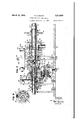
- Fig. 1 is a plan view of the invention and the essential parts of the associated selector and receiVer necessary for a clear understanding of the invention
- Fig. 2 is an enlarged vertical sectional view taken on the line 2-2 of Fig. 1;
- Fig. 3 is a left hand side elevational view of the orienting device and the selector mechanism
- Fig. 4 i a vertical sectional view taken on the line 4-.-4 of Fig. 1;
- Fig. 5 is a fragmentary vertical sectional view taken on line 55 of Fig. 1;
- Fig. 6 is a fragmentary vertical sectional view taken on line B-B of Fig. 1;
- Fig. 7 is a fragmentary vertical sectional View taken on line 1-1 of Fig. 1;
- Fig. 8 is a fragmentary vertical sectional view taken on line 88 of Fig. 2.
- of a continuously rotating motor furnishes through appropriate gearing and clutch mechanism, hereafter described, all local power for operating the receiver.
- a helical gear 22 fixed to the motor shaft meshes with another helical gear 23 located above.
- the helical gear 23 is fixed by'screws such as 24 to a gear hub 26 which in turn is secured to the printer operating shaft 2'! clamped in position by a bearing clamping mem-.
- the right hand end of the sleeve 36 is threaded and has nuts 31 thereon which clamp a printing cam 38 against a flange 39 of the sleeve 36 for rotation therewith.
- adjacent the center of the sleeve 36 has a collar 42 clamped against the left hand side thereof for rotation therewith by screws such as 43. Integral with the collar 42 is an irregular disk 44 which comprises another operating cam of the printer.
- the section 270 of the operating shaft is threaded and has a disk 54 thereon which clamps the inner "race 55 of the ball bearing unit and the disk 52' against the larger section 21a of the operating shaft for rotation therewith.
- the disk 52 is also keyed to the shaft 2'1 "and a lock unit 53 looks the disk 54 in place.
- a selector cam sleeve 51 is loosely mounted on section 27d of the operating shaft 21 and has a hub 58 on the right hand end thereof which is recessed and extends over the lock nut 53.
- a stop arm 66 is a stop arm 66, a cam 51, a series of five selector cams 63a to 68c, a selecting finger transfer cam 69 and a trip cam H intermediate with spacers 72. All these members and spacers are clamped together and against a shoulder 58a of the sleeve 51 by a nut 64 in threaded engagement with the left hand end of the sleeve 57.
- a third sleeve 74 hereinafter referred to as the pilot sleeve is loosely mounted adjacent the left hand end of the operating shaft 21. Clamped against the flange 16 of the pilot sleevefor rotation therewith by a nut 11 is a pilot sleeve stop arm 18 and a selector sleeve trip cam 19. Abutting the left hand end of the'pilot sleeve 14 is a collar 8
- a spring 86 surrounds the segments 84 and holds them in frictional engagement with the outer circumference of the section of the pilot sleeve 14 at the left of a flange 16.
- the segments 84 are substantially similar to the segments 82 which serve to rotate the selector cam sleeve 51 but are an appreciable amount smaller.
- the spring 86 surrounding the segments 84 has considerably less compression force than the spring 83 surrounding segments 62 and because of this fact the frictional force tending to rotate the selector cam sleeve 51 is considerably more than that tending to rotate the pilot sleeve 14; The reasons for this construction and the advantages thereof will hereinafter appear.
- a selector magnet mounting bracket 81 is secured to the front left hand corner of the base plate 34 by screws such as 88 and extending upwardly from the bracket are two supports 89 and 9
- a spring 99 attached to the cradle 94 tends to pivot the cradle and selector magnet in a clockwise direction as shown in Fig. 3 and hold a section I93 of the cradle in engagement with the top of a thumb nut I84 threaded on a stud I 8
- the cradle 94 with its attached members may extending projection III of the armature lever cooperates with the selectors as will be hereinafter described to selectively position the same.
- the substantially vertical arm I09 of the armature lever has adjustably secured thereto" by screws such as II3 a pilot sleeve stop arm anvil II4.
- the adjusting screw H9 is supported in the selector magnet cradle 94 and is locked in position by a lock nut I2I.
- Two adjusting screws I23 and I24 supported in the section 9I of the selector magnet bracket are engageab-le with the extension III of the armature lever and limit its movement.
- Another adjusting screw I22 cooperates with the armature 'I I2 to limit its movement when the selector magnet is energized.
- the two stops I22 and I24 are employed for the armature lever I01 to eliminate any bending or whip that might occur in the comparatively long and light armature extension III, the movement of which for reasons hereinafter apparent must be accurately controlled between comparatively small limits.
- an orienting plate I26 Secured to the base plate 34 at the left of the operating shaft 21 as shown in Fig. 3 is an orienting plate I26, the front side of which has a radial scale I21 etched thereon and a curved slot I28, the radius of curvature of which is equal to the distance therefrom to the center of the operating shaft 21.
- Attached to the horizontal top section of the orienting plate I26 by screws such as I29 is a downwardly extending bracket I3I.
- Mounted on the lower end of the bracket I3l is a Shoulder screw I32 shown dottedin Fig. 1 which has pivoted thereon at its left hand end a selec tor cam sleeve releasing lever I33, the right hand end of which extends beneath the operating shaft 21.
- a thumb nut I31 on the screw I34 permits it. to be clamped in any adjusted position in the curved slot I28 while an indicating member I38 movable withthe screw I84 cooperates with the scale I21 to indicate the amount of movement of the screw from one position to another.
- the adjustment of the lever I36 can be made equally well with the selector mechanism operating or at rest and it being adjustable while the selector is in operation greatly facilitates making its proper adjustment.
- the time of release of the selectorsleeve 5! with respect to a received group of signals may be varied without changing the rest position of said cam sleeve and the operations performed thereby can be distributed substantially throughout the complete revolution thereof.
- the speed of rotation of the shaft 21 is such with respect to the incoming line signals that the pilot sleeve I4 will complete a revolution while the rest impulse of the code group which caused its release is being received at the selector magnet 98.
- the rest impulses are closed line conditions which energize the magnet 98 and cause the anvil II4 to be moved into the path of the pilot sleeve stop arm. I8. Therefore, when the pilot sleeve subsequently completes its revolution the stop arm I8 and anvil H4 engage to stop the rotation of the pilot sleeve and it will remain at rest during the remainder of the rest impulse or until the start impulse of the following code group.
- the selector cam sleeve 51 and the pilot sleeve I4 are rotated from the.
- selector cam sleeve 51 will also be brought to rest at the. completion of every revolution for a length of'time equal to the time pilot sleeve is at rest.
- code combinations being received in a continuous succession which results in shorter rest impulses the two sleeves may not be at rest at the same time since the pilot sleeve I4 has to rotate a substantial amount before it can cause the release of the selector cam sleeve 51.
- a bracket I46 is secured to the base 34 by screws M1 in front of the operating shaft 21 and substantially opposite the selector cam sleeve 51. Extending horizontally from the bracket I46 are a series of studs and posts parallel with the shaft 2! on which are pivoted and mounted the selecting elements of the selector mechanism.
- Figs. 4, 5 and 6 are vertical sectional views taken progressively along the selector cam sleeve 51 and. show the manner in which the selector elements cooperate with the cam sleeve.
- a series of guide plates I52 Supported on three studs I48, I49 and I5I extending from the bracket I46 are a series of guide plates I52.
- the guide plates I52 are not fully shown in Figs. 5 and 6 but the shape thereof can readily be seen in Figs. 2 and 4.
- a series of collars or spacers I53 are located on the studs I48, I49 and I5I between the guide plates I52 and serve to space the guide plates along the studs.
- a set of nuts I54 threaded on the ends on the studs clamp the plates I52 and collars I53 together.
- a series of five selector levers indicated in general by reference numeral I56, Fig.
- each of the selector levers I56 is in operative relation with an associated one of the selector operating cams 68a to 68s on the selector cam sleeve 51.
- the right hand end of each selector lever I 56 is shaped to form a socket in which is pivotally carried the lower end of an associated selecting finger I5I.
- a depending arm I58 of each of the selector levers I56 has attached thereto one end of an individual spring I59, Fig.
- a bell crank I64 Extending horizontally toward the rear from the upper end of the substantially vertical arm of the, bell crank I64 is a section I66 against which the right hand upper ends of the selecting fingers I51 are normally held by their attached springs I62.
- a spring I6! attached to the bell crank I64 tends to rock it in a clockwise direction and normally holds a section I68 at the upper end against and hereinbefore described an adjustable length of:'
- Another bell crank I1I adjustably secured by a screw I12 and pin I13 to the leftwardly extending arm of the bell crank I64 has the upper end thereof in operative relation with the cam 61 on the selector sleeve 51.
- a section I14 of the bell crank I64 extends upward between the first two guide plates I52 and serves to keep the bell crank I1I in alignment with its associated cam 61.
- a lever I16, Fig. 6, is pivoted at its left hand end on the spacer I53 on the stud I48 behind the selector levers I56.
- the right hand end of the lever I16 rests on a bracket I11, extending from the main bracket I46.
- a pin I18 in the lever I16 pivotally supports a bell crank I19, the leftwardly extending arm of which pivotally carries a roller cam follower I8I which is in operative relation with the hereinbefore mentioned selector finger transfer cam 69.
- a plate I82 attached to the bracket I46 by screws such as I83, 20 Fig. 2, has a slot I84 therein which guides the left hand end of the bell crank I19. Supported on its lower end on the pin I18, Fig.
- a knife arm I86 which is adjustably secured to the bell crank I19 by a screw I81 extending through an elongated slot I88.
- the right hand end of the knife arm I86 has a bent vertical section I89 which is parallel to the operating shaft I81 and located a little to the left and above the upper ends of the selecting fingers I51 when they are in 3 0 its associated elements will now be described. 40
- the'selecting operation "consistsof 4 three separate operationswhichare asfollows: first, successively raising the selecting fingers I51 in timed relation'with received signalling imthereof to one'side or'the other of the knife'i *section I89 in accordance with received signals;
- the rotation of the cam sleeve 51 is initiated as time after the receipt of the'start impulse so that the selector cams 68 are effective to cooperate with associated selecting elements to selectively position the same during the mid-portion or most effective portion of respective signalling? impulses. While the selector-cam sleeve '51 is rotating the selector magnet 98, Fig. 3. positions the selector armature lever I81 in accordance length of time to insure the proper positioning I cordance with the first signalling impulse, the
- ciated selector lever I56 If the first signalling impulse is marking, the magnet 98 will be energized and position the armature extension III accordingly.
- a section of the armature extension III is shown by full lines in its marking position and bya dot-dash outline of the knife section I89.
- the upper ends of the selecting fingers 151 are bevelled toward the right and the lower edge of the knife section I89 is bevelled toward the left.
- bevelled projectionISB on the right hand side thereof'engages the armature extension l I I.
- This selecting finger I51 thereupon remains in this position until near the end of a revolution of the selector cam 51 when it is returned to its-normal position'as hereinafter described.
- the third, fourth and fifth selectingfingers I51 are successively. positioned to the left, or the right of, the knife section I89 in accordancewith received marking and spacing impulses respectively.
- the transfer operation is performed by moving transfer function.
- the transfer is performed by the transfer cam 69, Fig. 6, pivoting itsajssociated bell crank I19 to cause the knife seotio n I89 to move toward the left.
- This leftward movement of the knife section pivots the selecting fingers I51 on the left handside thereof a slight amount in a counter-clockwise direction.
- individual projections 203 formed in a stepped relation on the upper left hand sides engageassociated latchesv 2704, Fig, 7 to trip the same as will be hereinafter described.
- v A ta h ..to .t e base pla e is an, nv rt U- ha edm b r, 2133 i sl1- a inwiiic haste i d ne erti a yt e eir mlaus u .0I
- r o o -l a receiving selector m'echams'm responsive to received e combinations of e1e'ctrica1 1mo g elastic-magnet, a first rotaify heans initiated in rotation by the actuation tof saidlelectrb-n a gnft immediately preceding the reception of tether said code combinations and arrested in rotation irnifidiately following the reception for each of "said code c mbinations, a set of selecting fingers and a second rotatable member, adjustable I means ,”inter'pos'ed between said first and second iotaftame members for releasing saidseconQ mimetic member a Variable l ngth of ti e after the release of said first rotatable :I nember and means annoying said sec rid 'rotatabl eniember and said electr'o-ih'aghet for selecltively positioning 's
- I 2 I 2. I n a selecting mechanism, a shaft and means fgrrotating the shin a firstafid secon rotatable members fricti'onallir 'drivenby said shaft, an electric-magnet, irfeaiis :eentreue'd by said electro-Inagnet to release said first rotatable pa ers .p. v ta1 .r; nor th h rei qe qr i ned. tch s; 2.84. t lida l ounted t sc ew t 2 l endi e tic y. V r nc member 08 ar a.
- first and second pivoted levers means operated by said first rotatable member topivot said first ilv rqiiiaiis "operated by said first lever to pivot said -second"lever, in'eaiis controlled by said second lever to i'e1ase'snaseaand rotata'bleniernber for rotation, and means for to pivotsaid second le've'i", means 'coritrolld by said second 15% to release said s'e'c'or'idfrdtatable tatable member at various points in the rotation of said first rotatable member, and means for indicating the relative adjustment of said first lever.
- a rotating shaft a rotary distributor member normally at rest and tending to rotate with said shaft, a second rotatable member normally at rest and tending to rotate with said shaft, an electro-magnet response to received code combinations of impulses, means controlled by said electro-magnet to release said second rotatable member for rotation with said shaft at the beginning of each combination and arrest the same after one revolution at the completion of each combination, a first pivoted lever having a manually adjustable pivot point and adapted to be pivoted by said second rotatable member during the rotation thereof, a second pivoted lever normally restraining said distributor member from rotation, means operated by said first lever to pivot said second lever thereby releasing said distributor member for rotation with said shaft and means for adjusting the pivot point of said first lever whereby said second lever is pivoted to release said distributor member at any point within a predetermined part of the revolution of said second rotatable member.
- a rotating shaft a rotary distributor member normally at rest and tending to rotate with said shaft, a second rotatable member normally at rest and tending to rotate with said shaft, an electro-magnet responsive to received code combinations of impulses, means controlled by said electro-magnet to release said second rotatable member for rotation with said shaft at the beginning of each combination and arrest the same after one revolution at the completion of each combination, a first pivoted lever having a manually adjustable pivot point and adapted-to be pivoted by said second rotatable member during the rotation thereof, a second pivoted lever normally restraining said distributor member from rotation, means operated by said first lever to pivot said second lever thereby releasing said distributor member for rotation with said shaft, means for adjusting the pivot point of said first lever whereby said second lever is pivoted to release said distributor member at any point within a predetermined part of the revolution of said second rotatable member, a set of selectors and means embodying said distributor member and said electro-magnet' for selectively positioning said selectors
- a driving means a first and second rotatable members, means comprising a comparatively light and a comparatively heavy friction clutch interposed between said driving means and said first and second rotatable members respectively tending to rotate the same, a magnet, means controlled by said magnet to release said first rotatable member for rotation, means operated by the rotation PAUL A. NOXON.
Landscapes
- Engineering & Computer Science (AREA)
- General Engineering & Computer Science (AREA)
- Computer Networks & Wireless Communication (AREA)
- Signal Processing (AREA)
- Mechanical Engineering (AREA)
- Mechanical Operated Clutches (AREA)
Description
March 30, p NOXON TELEGRAPH ORIENTING DEVICE Original Filed Oct. 10, 1936 4 Sheets-Shet 1 OR P.A. NOXON ATTORNEY March so, 1943. P. A. NOXON v 2,315,009
TELEGRAPH ORIENTING DEVICE Original Filed Oct. 10, 1956 I 4 Sheets-Sheet 2 P a' "Q NVENTOR P.A.NOXON FIG. 8
ATTO R N EY P..A. NOXON TELEGRAPH ORIENTING DEVICE Ma ch 30; 1943.
Original 'Filed Oct. 10, 1936 4-Sh66tS-Sh66t 3 INVENTOR P.A.NOXON- BY I j ATTORNEY- March 30,1943. A N ON 2,315,009
TELEGRAPH OHIENTING DEVICE Original Filed Oct. 10, 1936 4 Sheets-Sheet 4 I99 ZOI ll I96 INVENTOR P.A. NOXON ATTORN EY Patented Mar. 30, 1943 UNITED STATES PATENT OFFICE TELEGRAPH ORIENTING DEVICE Paul A. Noxon, Tenafly, N. J., assignor to The Western Union Telegraph Company, New York, N. Y., a corporation of New York 7 Claims. (Cl. 178-531) This invention relates primarily to telegraph receiving mechanisms and more particularly to an orienting device for use in conjunction with the selector mechanism of telegraph receiving mechanisms. The invention is particularly adapted for use in conjunction with electric selector mechanisms of the type used to selectively control telegraph receivers and like apparatus employing the Baudot code, i. e., one in which the character signals are represented by groups of two different line conditions such as permutations of positive and negative impulses or current and no-current impulses extending throughout a definite number of, usually five, consecutive time intervals or units.
The present application is a divisional application of a copending application Serial No. 105,102, filed October 10, 1936, entitled "Electric selector mechanism, now Patent No. 2,209,998, granted Aug. 6, 1940.
'The novel features of this invention are particularly adaptable for use in conjunction with so-called start-stop or simplex telegraph systems, via, those employing creep wherein a rotatable member or distributor, such as a selector cam shaft or brush arm of the telegraph receiver is rotated a slight amount faster than a similar disr systems to provide a means for orienting, which operation in effect, entails the changing or varyferring the selection set up in the selectors to other elements, resetting the selectors, tripping 01f printing and letter spacing mechanisms, etc. Obviously, none of these functions should occur between the adjustable limits of the selector cam and consequently the adjustabilityv of its rest position reduces the operating time of these auxiliary functions and crowds them together. Another disadvantage in this type of orienting is that unless a separate adjustable start magnet is employed, a somewhat complicated linkage is often required between the selector magnet and the start mechanism wherein there is apt to be considerable lost motion which results in reduced operating marginof the selector mechanism. Accordingly, the primary object of this invention is to provide a novel and simplified means for orienting telegraph receivers or compensating for variable starting line conditions withoutchanging the rest position of the distributor member of the associated selector mechanism and thereby making the entire rotating time of the distributor member available for selector operation and auxiliary functions.
It is the usual practice in operating on the start-stop principle to have the selector magnet, or a separate start magnet in series or parallel with the selector magnet, release the rotatable distributor member,- such as the cam shaft or sleeve. This shaft or sleeve is usually frictionally driven and normally tending ing the stop or rest position of the rotatable mem- 1 ber at the telegraph receiver to compensate for line and other conditions which may tend to vary the length and effectiveness of the start impulse so that the rotatable member, such as the selector cam shaft, is operative on associated selectors to rotate, and as thecam shaft has a considerable amount of work to perform, ;a comparatively heavy friction clutch mustbe employed; Otherwise slippage might occur between the driving member and the cam shaft which would result in incorrect operation of the selector. With a heavy friction clutch, a heavier load is put on the start magnet or selector magnet to release the cam shaft for rotation and consequently the release is apt not to take place non-uniformly with respect to the start impulse. It is, therefore, an-
other object of this invention to provide a mech- V the selector cam shaft is reduced, and thereby enabling the start of the cam shaft to be more easily controlled.
Other objects of the invention reside in its rc- V A liability, its ease of adjustment, its simplicity, and
minimum number of parts employed toeccomplish the above objects. i
telegraph machines detailed description and drawings thereof, and particularly in the appended claims.
The preferred embodiment of the invention as shown in the accompanying drawings is particularly adapted for use in conjunction with the selector mechanism disclosed in the above mentioned copending application, which in turn is preferably used to control the operation of a type bar printer of the type disclosed in another copending application of P. A. Noxon et al., filed March 3, 1936, Ser. No. 66,906, and only such parts of the selector mechanism and. the printer are shown and described herein as are thought necessary for a complete understanding of this invention. It should be evident, however, that the use of the orienting device is not limited to this particular type of selector but may readily be adapted for use in conjunction with practically any one or all telegraph receivers operating on the start-stop principle. 4
In the preferred embodiment of the invention the orienting mechanism consists of a frictionally driven rotatable member which is released for rotation by the selector magnet in response to the start impulse of each code combination. A manually adjustable means operated by this rotatable member causes the release of the selector cam sleeveof the associated selector mechanism and by use of the manually adjustable means, the time interval elapsing between the release of the first rotatable member and the selector cam sleeve is varied or adjusted to compensate for the variable start impulse of each group to allow the selector cams to cooperate with the selectors during the most effective portion of their associated signaling impulses. 7
A more complete and thorough understanding of the invention may be had from the following detailed description taken in conjunction with the accompanying drawings, showing a preferred embodiment thereof, in the latter of which:
Fig. 1 is a plan view of the invention and the essential parts of the associated selector and receiVer necessary for a clear understanding of the invention;
Fig. 2 is an enlarged vertical sectional view taken on the line 2-2 of Fig. 1;
Fig. 3 is a left hand side elevational view of the orienting device and the selector mechanism;
Fig. 4 i a vertical sectional view taken on the line 4-.-4 of Fig. 1;
Fig. 5 is a fragmentary vertical sectional view taken on line 55 of Fig. 1;
Fig. 6 is a fragmentary vertical sectional view taken on line B-B of Fig. 1;
Fig. 7 is a fragmentary vertical sectional View taken on line 1-1 of Fig. 1; and
Fig. 8 is a fragmentary vertical sectional view taken on line 88 of Fig. 2.
Referring first to Fig. 1 a motor shaft 2| of a continuously rotating motor, not shown, furnishes through appropriate gearing and clutch mechanism, hereafter described, all local power for operating the receiver. A helical gear 22 fixed to the motor shaft meshes with another helical gear 23 located above. The helical gear 23 is fixed by'screws such as 24 to a gear hub 26 which in turn is secured to the printer operating shaft 2'! clamped in position by a bearing clamping mem-.
ber 32. The right hand end of the operating on will now be described and throughout the description various sections of the operating shaft will hereinafter be referred to as sections 21a, 27b,
' etc. Referring to Fig. 2, a normally at rest printing operating cam sleeve 36 is loosely mounted on sections 21a of the operating shaft abutting at its'right hand end a collar 2lb= integral with the shaft 21. The right hand end of the sleeve 36 is threaded and has nuts 31 thereon which clamp a printing cam 38 against a flange 39 of the sleeve 36 for rotation therewith. Another flange 4| adjacent the center of the sleeve 36 has a collar 42 clamped against the left hand side thereof for rotation therewith by screws such as 43. Integral with the collar 42 is an irregular disk 44 which comprises another operating cam of the printer. The operation of these cams and the manner in which they control the associated printer are fully described in the above mentioned copending application, Serial No. 105,102. Loosely mounted on the left hand end of the sleeve 36 is another collar 43 which is at all times operatively engaged with the collar 42 by means of interengaging tongues and grooves 41 and 43 formed on the collars 42 and'45. Thus the collar 46 is rotatable with the sleeve 36 but is slideablealong the sleeve by means hereinafter described to bring ratchet teeth 49 disposed on the left hand face thereof into and out of engagementwith similar teeth 5| disposed on the right hand face of a disk member 52. V I v The section 270 of the operating shaft is threaded and has a disk 54 thereon which clamps the inner "race 55 of the ball bearing unit and the disk 52' against the larger section 21a of the operating shaft for rotation therewith. The disk 52 is also keyed to the shaft 2'1 "and a lock unit 53 looks the disk 54 in place.
A selector cam sleeve 51 is loosely mounted on section 27d of the operating shaft 21 and has a hub 58 on the right hand end thereof which is recessed and extends over the lock nut 53. EX-
tending horizontally from the left hand face of the disk 54 are a series of three pins 59, each of which is engaged in a slot 6|, Fig. 8, in an associated segment 62 of a segmented ring composed of three segments of Bakelite of some other suitable friction material. Surrounding the segments 62 is a circular coiled radially contractable spring 63 which holds the inner surfaces of the segments 62 fractionallyengaged with the outer surface of the hub 58. Thus as the disk 54 and pins 59 rotate with the continuously rotating operating shaft 21, the segments rotate therewith and also tend to rotate the sleeve v51. However, the sleeve 51 is normally held at rest by means hereinafter described. Mounted from let to right on the sleeve 5'! is a stop arm 66, a cam 51, a series of five selector cams 63a to 68c, a selecting finger transfer cam 69 and a trip cam H intermediate with spacers 72. All these members and spacers are clamped together and against a shoulder 58a of the sleeve 51 by a nut 64 in threaded engagement with the left hand end of the sleeve 57.
A third sleeve 74 hereinafter referred to as the pilot sleeve is loosely mounted adjacent the left hand end of the operating shaft 21. Clamped against the flange 16 of the pilot sleevefor rotation therewith by a nut 11 is a pilot sleeve stop arm 18 and a selector sleeve trip cam 19. Abutting the left hand end of the'pilot sleeve 14 is a collar 8| which is secured by a screw 82 to the operating shaft 21 for rotation therewith. Extending from the right hand face of the collar BI are a series of pins 83 which engage segments 84 of a segmented ring. A spring 86 surrounds the segments 84 and holds them in frictional engagement with the outer circumference of the section of the pilot sleeve 14 at the left of a flange 16. The segments 84 are substantially similar to the segments 82 which serve to rotate the selector cam sleeve 51 but are an appreciable amount smaller. The spring 86 surrounding the segments 84 has considerably less compression force than the spring 83 surrounding segments 62 and because of this fact the frictional force tending to rotate the selector cam sleeve 51 is considerably more than that tending to rotate the pilot sleeve 14; The reasons for this construction and the advantages thereof will hereinafter appear.
Referring now to Figs. 1 and 3, the arrangement of the selector magnet will now be described. A selector magnet mounting bracket 81 is secured to the front left hand corner of the base plate 34 by screws such as 88 and extending upwardly from the bracket are two supports 89 and 9| in which are threaded two hollow ended screws 92. Extending horizontally between the two screws and pivotally supported therein is a selector armature lever pivot rod 93. Pivotally mounted on shoulders at the inner ends of the screws 92 is a substantially U-shaped selector magnet mounting cradle 94 which has secured thereto by screws 95 a magnet yoke 91 and the two coils of the selector magnet 98. A spring 99 attached to the cradle 94 tends to pivot the cradle and selector magnet in a clockwise direction as shown in Fig. 3 and hold a section I93 of the cradle in engagement with the top of a thumb nut I84 threaded on a stud I 8| extending'vertically from the bracket 91. By adjusting the nut I84 the cradle 94 with its attached members may extending projection III of the armature lever cooperates with the selectors as will be hereinafter described to selectively position the same. The substantially vertical arm I09 of the armature lever has adjustably secured thereto" by screws such as II3 a pilot sleeve stop arm anvil II4. A slot H9 in the anvil II4, through which the .screw II3 extends, permits relative adjustment between the armature lever extension I89 and the anvil H4. With the selector magnet 98 energized, which is its normal condition, the tip of the anvil I I4 is in the path of or engaged with the end of the pilot sleeve stop arm 18 and thereby normally arrests the rotation of the pilot sleeve 14. On deenergization of the magnet 98 a spring I I1 secured to a pin H8 in the armature extension I99 and to an adjusting screw I I 9 pivots the armature lever in a clockwise direction to withdraw the anvil II4 from out of engagement with the stop arm 18 whereupon the pilot sleeve 14 is free to rotate with the operating shaft 21. The adjusting screw H9 is supported in the selector magnet cradle 94 and is locked in position by a lock nut I2I. Two adjusting screws I23 and I24 supported in the section 9I of the selector magnet bracket are engageab-le with the extension III of the armature lever and limit its movement. Another adjusting screw I22 cooperates with the armature 'I I2 to limit its movement when the selector magnet is energized. The two stops I22 and I24 are employed for the armature lever I01 to eliminate any bending or whip that might occur in the comparatively long and light armature extension III, the movement of which for reasons hereinafter apparent must be accurately controlled between comparatively small limits.
Secured to the base plate 34 at the left of the operating shaft 21 as shown in Fig. 3 is an orienting plate I26, the front side of which has a radial scale I21 etched thereon and a curved slot I28, the radius of curvature of which is equal to the distance therefrom to the center of the operating shaft 21. Attached to the horizontal top section of the orienting plate I26 by screws such as I29 is a downwardly extending bracket I3I. Mounted on the lower end of the bracket I3l is a Shoulder screw I32 shown dottedin Fig. 1 which has pivoted thereon at its left hand end a selec tor cam sleeve releasing lever I33, the right hand end of which extends beneath the operating shaft 21. Extending through the slot I28 in the bracket I26 is another shoulder screw I34 which has pivotally mounted thereon at its left hand end a pilot sleeve operating lever I36 which also extends beneath the operating shaft 21 and this lever with the selector cam sleeve releasing lever I33 cooperate with one another to release the selector cam sleeve 51 as will be hereinafter described. A thumb nut I31 on the screw I34 permits it. to be clamped in any adjusted position in the curved slot I28 while an indicating member I38 movable withthe screw I84 cooperates with the scale I21 to indicate the amount of movement of the screw from one position to another.
In the right hand end of the lever I36 is a horizontal stud I39 which pivotally supports two rollers I48 and MI, Fig. 2. The roller I48 is in,
operative relation with the selector sleeve trip cam 19 and the roller I4I engages the right hand curved section I42 of the lever.l33. A spring I43 secured to the lever I33 tends to pivot it in a counter-clockwise direction as shown in Fig. 3 and holds the curved section I42 in engagement with the roller MI, and as the rollers I49 and MI are on a common stud, the spring I43 also holds the roller I49 in contact with the periphery of the selector sleeve trip cam 19, Extending from the side of the lever I83is a curved projection I44, Figs. 1, 2 and 3, the end of which is normally engaged with the end of the selector sleeve stop arm 69 and thereby keeps the selector sleeve 51 and its attached elements from rotating. When a start pulse is received on the selector magnet 98, which is an open line condition, the spring I81,
1 Fig. 3', withdraws the anvil II4 from out of engagement with the pilot sleeve stop arm 18 whereupon the pilot sleeve 14 is free to rotate. After the pilot sleeve has rotated about a quarter of a revolution fromits rest position, the hump section of the selector sleeve trip cam 19 rotates into operative relationw ith the roller I48 to force it downward and cause a clockwise pivoting movement of the lever I39about it s'left hand end on the shoulder screw I34. The ro11er'I4I also movesdownward with the roller I48. and in so in a clockwise direction about its left hand end on the shoulder screw I32. This pivoting movement of the lever I33 withdraws the end of the projection I44 from out of engagement with the selector sleeve stop arm 66 whereupon the selector sleeve 51 is free to rotate with the main operating shaft 21 through the action of its associated riction clutch hereinbefore described. The radius of curvature of the section I42 of the lever I33 is equal to the diameter of its associated roller I4I plus the normal radius of the selector sleeve trip cam I9 and when the left hand end of the lever I36 on the shoulder screw I34 is moved within the limits of the curved slot I28, the roller I49 moves along the curved section I42 of the lever I33. Throughout the adjustable position of the lever I36. the roller I40 is not engageable with the hump of the cam I9 and therefore adjusting the left hand and of the lever I36 will not cause the release of the selector cam sleeve 51.
From the above it is evident that by moving the shoulder screw I34 and the left hand end of the lever I36 within th limits of the curved slot I28 the amount of rotation of the selector sleeve trip cam I9 and the pilot sleeve I4 from their normal rest position necessary to cause the release of the selector sleeve 5! may be varied. In this manner the variable lengths of the starting impulses due to line and other conditions may be compensated for and allows the selecting cams 68a to 68e to be operatively associated with their respective elements during the midportion or most effective portions of their respective signaling impulses as will be hereinafter described. Obviously the adjustment of the lever I36 can be made equally well with the selector mechanism operating or at rest and it being adjustable while the selector is in operation greatly facilitates making its proper adjustment. Thus the time of release of the selectorsleeve 5! with respect to a received group of signals may be varied without changing the rest position of said cam sleeve and the operations performed thereby can be distributed substantially throughout the complete revolution thereof.
The speed of rotation of the shaft 21 is such with respect to the incoming line signals that the pilot sleeve I4 will complete a revolution while the rest impulse of the code group which caused its release is being received at the selector magnet 98. The rest impulses are closed line conditions which energize the magnet 98 and cause the anvil II4 to be moved into the path of the pilot sleeve stop arm. I8. Therefore, when the pilot sleeve subsequently completes its revolution the stop arm I8 and anvil H4 engage to stop the rotation of the pilot sleeve and it will remain at rest during the remainder of the rest impulse or until the start impulse of the following code group. The selector cam sleeve 51 and the pilot sleeve I4 are rotated from the. same shaft 21 and therefore rotate at the same speed. Accordingly the selector cam sleeve 51 will also be brought to rest at the. completion of every revolution for a length of'time equal to the time pilot sleeve is at rest. However with code combinations being received in a continuous succession which results in shorter rest impulses the two sleeves may not be at rest at the same time since the pilot sleeve I4 has to rotate a substantial amount before it can cause the release of the selector cam sleeve 51.
All the work the pilot sleeve has to perform is done by the cam I9 pivoting the levers I33 and doing pivots the selector sleeve release lever I 33- I36 against the action of the spring I43. The spring I43 may be comparatively weak and the slope of the cam I9 gradual and therefore the frictional force tending to rotate the pilot sleeve I4 may be very small. With a small frictional force tending to rotate the pilot sleeve the anvil II4 may be easily withdrawn from engagement with the pilot sleeve stop arm I8 and consequently the amount of work performed by the selector magnet to initiate the operation of the selector mechanism is comparatively small. This feature is another advantage of the above arrangement and very helpful when the selector is operating in response to weak signals.
Referring now to Figs. 2, 4, 5 and 6' a bracket I46 is secured to the base 34 by screws M1 in front of the operating shaft 21 and substantially opposite the selector cam sleeve 51. Extending horizontally from the bracket I46 are a series of studs and posts parallel with the shaft 2! on which are pivoted and mounted the selecting elements of the selector mechanism. Figs. 4, 5 and 6 are vertical sectional views taken progressively along the selector cam sleeve 51 and. show the manner in which the selector elements cooperate with the cam sleeve.
Supported on three studs I48, I49 and I5I extending from the bracket I46 are a series of guide plates I52. In order to more clearly illustrate the elements of the selector mechanism the guide plates I52 are not fully shown in Figs. 5 and 6 but the shape thereof can readily be seen in Figs. 2 and 4. A series of collars or spacers I53 are located on the studs I48, I49 and I5I between the guide plates I52 and serve to space the guide plates along the studs. A set of nuts I54 threaded on the ends on the studs clamp the plates I52 and collars I53 together. In between the spaces formed between the guide plates I52 are a series of five selector levers indicated in general by reference numeral I56, Fig. 5, which are pivotally supported on the spacers I53 on the stud I48. The selector levers I56 are slightly thinner than the spacers I 53 and therefore free movement thereof between the guide plates I52 is permitted. The left hand end I55, Fig. 5, of each of the selector levers I56 is in operative relation with an associated one of the selector operating cams 68a to 68s on the selector cam sleeve 51. The right hand end of each selector lever I 56 is shaped to form a socket in which is pivotally carried the lower end of an associated selecting finger I5I. A depending arm I58 of each of the selector levers I56 has attached thereto one end of an individual spring I59, Fig. 4, which tends to pivot the lever in a clockwise direction and holds the left hand ends I55 of each lever in engagement with its associated cam 68. The other ends of the springs I59 are anchored to a post I6I in the bracket I46. Attached to each one of the selecting fingers I5I adjacent the center thereof are individually associated springs I62 which tend to pivot the fingers in a clockwise direction.
Pivoted on a spacer I53 on the stud I49 be tween the first and second guide plates I52 and in front of the selector levers I56 as shown in Figs. 4 and 5 is a bell crank I64. Extending horizontally toward the rear from the upper end of the substantially vertical arm of the, bell crank I64 is a section I66 against which the right hand upper ends of the selecting fingers I51 are normally held by their attached springs I62. A spring I6! attached to the bell crank I64 tends to rock it in a clockwise direction and normally holds a section I68 at the upper end against and hereinbefore described an adjustable length of:'
of the armature lever and extension III in acfirst selecting cam 68:; rotates into engagement with the projection I55, Figs. 'ito 5,1011 its asap- 75" hand side of. the'knife' ection,1enter into this adjusting screw I69. Another bell crank I1I adjustably secured by a screw I12 and pin I13 to the leftwardly extending arm of the bell crank I64 has the upper end thereof in operative relation with the cam 61 on the selector sleeve 51. A section I14 of the bell crank I64 extends upward between the first two guide plates I52 and serves to keep the bell crank I1I in alignment with its associated cam 61.
A lever I16, Fig. 6, is pivoted at its left hand end on the spacer I53 on the stud I48 behind the selector levers I56. The right hand end of the lever I16 rests on a bracket I11, extending from the main bracket I46. A pin I18 in the lever I16 pivotally supports a bell crank I19, the leftwardly extending arm of which pivotally carries a roller cam follower I8I which is in operative relation with the hereinbefore mentioned selector finger transfer cam 69. A plate I82 attached to the bracket I46 by screws such as I83, 20 Fig. 2, has a slot I84 therein which guides the left hand end of the bell crank I19. Supported on its lower end on the pin I18, Fig. 6, is a knife arm I86 which is adjustably secured to the bell crank I19 by a screw I81 extending through an elongated slot I88. The right hand end of the knife arm I86 has a bent vertical section I89 which is parallel to the operating shaft I81 and located a little to the left and above the upper ends of the selecting fingers I51 when they are in 3 0 its associated elements will now be described. 40
In general the'selecting operation "consistsof 4 three separate operationswhichare asfollows: first, successively raising the selecting fingers I51 in timed relation'with received signalling imthereof to one'side or'the other of the knife'i *section I89 in accordance with received signals;
second, the transfer operation which is performed by the movement of the knife section I89 which causes-the selecting finger-'I51-on the left side thereof to trip associated latches normal- 3 1y latching associated permutation bars in a normalposition; and, third; the reset'of the knife 5 In Fig. 4 the selector cam sleeve 51 and its associated elements are shown in their normal rest position while in Figs. 5 and-6 someof the elements are shown in their operated positions.
The rotation of the cam sleeve 51 is initiated as time after the receipt of the'start impulse so that the selector cams 68 are effective to cooperate with associated selecting elements to selectively position the same during the mid-portion or most effective portion of respective signalling? impulses. While the selector-cam sleeve '51 is rotating the selector magnet 98, Fig. 3. positions the selector armature lever I81 in accordance length of time to insure the proper positioning I cordance with the first signalling impulse, the
ciated selector lever I56. If the first signalling impulse is marking, the magnet 98 will be energized and position the armature extension III accordingly. In Figs. 4 to 6 a section of the armature extension III is shown by full lines in its marking position and bya dot-dash outline of the knife section I89. The upper ends of the selecting fingers 151 are bevelled toward the right and the lower edge of the knife section I89 is bevelled toward the left. With the first impulse of a group assumed to be marking the armature extension III will be positioned accordingly and as the selecting finger I51 rises 21. bevelled projectionISB: on the right hand side thereof'engages the armature extension l I I. This engagement of the projection I98 with the arma- -ture extension I II causes a slight pivoting movement in a counter-clockwise direction-of the selecting finger I51, which is sufiicient to bring the top bevelled surface I96 thereon beneath the bevelled surface. I91 on the knife section I89. Further-upward movement of the selecting finger I51 then causes the bevelled surfaces I96 and I91 to engage and move the finger a slight amount toward theleft and'it passes to the left of the knife section I89 to a position as shown in Fig. 6.
This selecting finger I51 thereupon remains in this position until near the end of a revolution of the selector cam 51 when it is returned to its-normal position'as hereinafter described. A
member I99 adjustably secured to the knife arm I86 bya screw 28I'has a horizontal section 282 parallel tdthe-knife section I89. The purpose pulses and selectively positioning the upper ends of "the section-"2821s to prevent overthrow of the Following the positioning of I thefirst selecting finger 151 the armature lever I01 and armature extension III are positioned in accordance withthe second selecting impulse and if this impulse is assumed to be a-spacing impulse, the armature extension will be moved to its-spacing position, after which the high part of the selector cam 68b engages the end of the second selector lever I56 This raises the associated selecting finger I51, and with the'armature extension III in its spacing positionthe bevelled projection I98 on-the finger will not engage the extension III. Thus the second selector finger I41 slides upward on the section I66 of the bell crank I64 and the -upperend thereof passes to the right of the knife section 189 as shown in Fig. 5.
In a similar manner the third, fourth and fifth selectingfingers I51, are successively. positioned to the left, or the right of, the knife section I89 in accordancewith received marking and spacing impulses respectively.
with the received impulses; After a suiiicient After the selective positioning of the selecting fingers I51 the next function is the transfer operation. Thisfunctionis performed by moving transfer function. The transfer is performed by the transfer cam 69, Fig. 6, pivoting itsajssociated bell crank I19 to cause the knife seotio n I89 to move toward the left. This leftward movement of the knife section pivots the selecting fingers I51 on the left handside thereof a slight amount in a counter-clockwise direction. As the selecting fingers, J51 arethus pivoted, individual projections 203 formed in a stepped relation on the upper left hand sides engageassociated latchesv 2704, Fig, 7 to trip the same as will be hereinafter described. A 1, V During the time thekn fe section l8 is holdns t e markingly os ti n d ele ti fin er i the left, the cam 61, Big, 5, rocksthe bell crank 164 which pivots the spacingly positioned selecting fingers a slight amount in a c0unter clockwise direction. This pivoting movement of the spacingly positioned selecting fingers is notspfficient, however, to cause their projections 203 to trip associated latches. While the spacingly and markingly positioned, selecting fingfirs are thils held to the left by the bell crank I64 and knife section I89 respectively, the sections i535 of the selector levers I56 simultaneously pass outof operative relation with the high part of th ir associated selected cams 68 whereupqn the selecting fingers drop down and those markin y p sit o d p vo o w s to age t e EQiiO 1h ierce en a es an m 0 11 a t nll ve t 201 to initiate the operation of the operating mosl eve-3.
v A ta h ..to .t e base pla e is an, nv rt U- ha edm b r, 2133 i sl1- a inwiiic haste i d ne erti a yt e eir mlaus u .0I
Bus i s 21 9 1 he d 2P9 n m d ate wit 011a]; which theteth 51 an the collar 52 in a ii newe c r r 'lhe operation of the operating cam sleeve 36 and the manner which it centres the associated printr 'i's 'f'u'lly described in the 'do'pendmg application bf et 'al., Ser. No. 6,906.
Althoiigh this 'invehtio'n h'owh and described 1h ebiijuntiah with e seieto mechanism controlling a recorder of a particiil'ar "type, it is obvioiis, of cofir's, that it may be employed in conjunction with various other types of selectors and that various modifications er the apparatus shown and described herein be made with out departing from the sp rit or essential attribiites of the invehtioh, and it is desired, therefore, that onl'v such limitations shall be placed thereon as are ir'nposed by the prior art or are specifically set forth in the appended claims.
What is claimed is': r o o -l. a receiving selector m'echams'm responsive to received e combinations of e1e'ctrica1 1mo g elastic-magnet, a first rotaify heans initiated in rotation by the actuation tof saidlelectrb-n a gnft immediately preceding the reception of tether said code combinations and arrested in rotation irnifidiately following the reception for each of "said code c mbinations, a set of selecting fingers and a second rotatable member, adjustable I means ,"inter'pos'ed between said first and second iotaftame members for releasing saidseconQ mimetic member a Variable l ngth of ti e after the release of said first rotatable :I nember and means annoying said sec rid 'rotatabl eniember and said electr'o-ih'aghet for selecltively positioning 'sa'id selecting fingers in accordance with the received code combinations.
I 2. I n a selecting mechanism, a shaft and means fgrrotating the shin a firstafid secon rotatable members fricti'onallir 'drivenby said shaft, an electric-magnet, irfeaiis :eentreue'd by said electro-Inagnet to release said first rotatable pa ers .p. v ta1 .r; nor th h rei qe qr i ned. tch s; 2.84. t lida l ounted t sc ew t 2 l endi e tic y. V r nc member 08 ar a. e e pf five, in ivid ll lQiQhQiPfi tflfiQp b rs 18- 7. Normal y th Per ut tion. ba s a i ,th rr e t, han ros We a he d .by ei o as ociated a qh 29 against the action of individually single wire Sh ine .2?
Be flring newl q F s it? nd fie cit is lmed t a the fi st, four and th o th se eeii e fin er 57 are Pos t o to. h le of th e i ec on. U3 their e ajn eiq 29 will enga th s r t e first, fourth and fifth latches 2047 from the top as the knife section moves to the left. This allows the first fourth and fifth of the permutation bars to slide to the left andv selectively control the associated recorder. r o H Referring now to Figs. 1, 2 and 4, a bracket 23! attached to the bearing post 3| 'byscrews 232 pivotally supports a. rod 233 upon which is mounted the above mentioned t'rip lever 20'! between collars 234. A spring 236 attached to the trip lever keeps the depending arm 231 in contact with the periphery of the collar 46. A side cam'surfa'ce 238 -on the collar 4'5cooper'at'es -with the depending arm 231 to control the engagement and disengagement of the teeth '49 on -the memberfor rotation, first 'a'nd secohd pivoted levr s fiie 'p fa l FY I i d' a rr ernber to pivcitsai'd first lev r, meats operated by sa-id firstle'ver to pivot said seeana lever and means @neneaty' said second lever to 'relas'e said second nameihentei for rotation.
B In a selectingrnechaifism,a shaft and hieans for rotating the saint, first the second 'iotatable membersffrictionalB' seventy 'saia than, an
t ag t to release said 'rdtatkatie reenter for rotation, first and second pivoted levers, means operated by said first rotatable member topivot said first ilv rqiiiaiis "operated by said first lever to pivot said -second"lever, in'eaiis controlled by said second lever to i'e1ase'snaseaand rotata'bleniernber for rotation, and means for to pivotsaid second le've'i", means 'coritrolld by said second 15% to release said s'e'c'or'idfrdtatable tatable member at various points in the rotation of said first rotatable member, and means for indicating the relative adjustment of said first lever.
5. In an electrical selecting mechanism, a rotating shaft, a rotary distributor member normally at rest and tending to rotate with said shaft, a second rotatable member normally at rest and tending to rotate with said shaft, an electro-magnet response to received code combinations of impulses, means controlled by said electro-magnet to release said second rotatable member for rotation with said shaft at the beginning of each combination and arrest the same after one revolution at the completion of each combination, a first pivoted lever having a manually adjustable pivot point and adapted to be pivoted by said second rotatable member during the rotation thereof, a second pivoted lever normally restraining said distributor member from rotation, means operated by said first lever to pivot said second lever thereby releasing said distributor member for rotation with said shaft and means for adjusting the pivot point of said first lever whereby said second lever is pivoted to release said distributor member at any point within a predetermined part of the revolution of said second rotatable member.
6. In an electrical selecting mechanism, a rotating shaft, a rotary distributor member normally at rest and tending to rotate with said shaft, a second rotatable member normally at rest and tending to rotate with said shaft, an electro-magnet responsive to received code combinations of impulses, means controlled by said electro-magnet to release said second rotatable member for rotation with said shaft at the beginning of each combination and arrest the same after one revolution at the completion of each combination, a first pivoted lever having a manually adjustable pivot point and adapted-to be pivoted by said second rotatable member during the rotation thereof, a second pivoted lever normally restraining said distributor member from rotation, means operated by said first lever to pivot said second lever thereby releasing said distributor member for rotation with said shaft, means for adjusting the pivot point of said first lever whereby said second lever is pivoted to release said distributor member at any point within a predetermined part of the revolution of said second rotatable member, a set of selectors and means embodying said distributor member and said electro-magnet' for selectively positioning said selectors during the rotation of said distributor member in response to and in accordance with received combinations.
7. In a selector mechanism, a driving means, a first and second rotatable members, means comprising a comparatively light and a comparatively heavy friction clutch interposed between said driving means and said first and second rotatable members respectively tending to rotate the same, a magnet, means controlled by said magnet to release said first rotatable member for rotation, means operated by the rotation PAUL A. NOXON.
Priority Applications (1)
| Application Number | Priority Date | Filing Date | Title |
|---|---|---|---|
| US223384A US2315009A (en) | 1936-10-10 | 1938-08-06 | Telegraph orienting device |
Applications Claiming Priority (2)
| Application Number | Priority Date | Filing Date | Title |
|---|---|---|---|
| US105102A US2209998A (en) | 1936-10-10 | 1936-10-10 | Electric selector mechanism |
| US223384A US2315009A (en) | 1936-10-10 | 1938-08-06 | Telegraph orienting device |
Publications (1)
| Publication Number | Publication Date |
|---|---|
| US2315009A true US2315009A (en) | 1943-03-30 |
Family
ID=26802256
Family Applications (1)
| Application Number | Title | Priority Date | Filing Date |
|---|---|---|---|
| US223384A Expired - Lifetime US2315009A (en) | 1936-10-10 | 1938-08-06 | Telegraph orienting device |
Country Status (1)
| Country | Link |
|---|---|
| US (1) | US2315009A (en) |
Cited By (1)
| Publication number | Priority date | Publication date | Assignee | Title |
|---|---|---|---|---|
| US2795647A (en) * | 1954-04-27 | 1957-06-11 | Siemens Ag | Start-stop teleprinter receivers |
-
1938
- 1938-08-06 US US223384A patent/US2315009A/en not_active Expired - Lifetime
Cited By (1)
| Publication number | Priority date | Publication date | Assignee | Title |
|---|---|---|---|---|
| US2795647A (en) * | 1954-04-27 | 1957-06-11 | Siemens Ag | Start-stop teleprinter receivers |
Similar Documents
| Publication | Publication Date | Title |
|---|---|---|
| US2154512A (en) | Facsimile printing telegraph system and apparatus | |
| US1969926A (en) | Dial and switch mechanism | |
| US2315009A (en) | Telegraph orienting device | |
| US1548168A (en) | Printing telegraphy | |
| US2209998A (en) | Electric selector mechanism | |
| US2375541A (en) | Telegraph printer | |
| US2525957A (en) | Projection system | |
| US2329652A (en) | Printing telegraph apparatus | |
| US2754361A (en) | Selector mechanism | |
| US2273083A (en) | Telegraph storage transmitter | |
| US2021382A (en) | Remote control system | |
| US2135377A (en) | Telegraph transmitter | |
| US2238090A (en) | Printing telegraph apparatus | |
| US2351137A (en) | Telegraph apparatus | |
| US2308306A (en) | Printing telegraph apparatus | |
| US1745633A (en) | Telegraph receiver | |
| US2555622A (en) | Printing telegraph apparatus | |
| US2264186A (en) | Telegraph keyboard transmitter | |
| US2359494A (en) | Selective signal device | |
| US2146380A (en) | Printing telegraph apparatus | |
| US2754364A (en) | Keyboard transmitter | |
| US2034806A (en) | Telegraph testing system | |
| US2231215A (en) | Telegraph printer | |
| US2334205A (en) | Selective switching | |
| US2273032A (en) | Dual magazine control |