US2314570A - Throttle control - Google Patents
Throttle control Download PDFInfo
- Publication number
- US2314570A US2314570A US360476A US36047640A US2314570A US 2314570 A US2314570 A US 2314570A US 360476 A US360476 A US 360476A US 36047640 A US36047640 A US 36047640A US 2314570 A US2314570 A US 2314570A
- Authority
- US
- United States
- Prior art keywords
- engine
- throttle
- speed
- sleeve
- drive
- Prior art date
- Legal status (The legal status is an assumption and is not a legal conclusion. Google has not performed a legal analysis and makes no representation as to the accuracy of the status listed.)
- Expired - Lifetime
Links
- 230000033001 locomotion Effects 0.000 description 69
- 230000000979 retarding effect Effects 0.000 description 35
- 239000004020 conductor Substances 0.000 description 26
- 230000005540 biological transmission Effects 0.000 description 24
- 230000004044 response Effects 0.000 description 22
- 230000008859 change Effects 0.000 description 19
- 239000012530 fluid Substances 0.000 description 19
- 230000009471 action Effects 0.000 description 14
- 230000008878 coupling Effects 0.000 description 14
- 238000010168 coupling process Methods 0.000 description 14
- 238000005859 coupling reaction Methods 0.000 description 14
- XDDAORKBJWWYJS-UHFFFAOYSA-N glyphosate Chemical compound OC(=O)CNCP(O)(O)=O XDDAORKBJWWYJS-UHFFFAOYSA-N 0.000 description 11
- 238000009877 rendering Methods 0.000 description 10
- 230000000903 blocking effect Effects 0.000 description 8
- 230000000694 effects Effects 0.000 description 8
- 230000008030 elimination Effects 0.000 description 7
- 238000003379 elimination reaction Methods 0.000 description 7
- 230000007246 mechanism Effects 0.000 description 7
- 230000002441 reversible effect Effects 0.000 description 7
- 230000003111 delayed effect Effects 0.000 description 4
- 230000001360 synchronised effect Effects 0.000 description 4
- 230000000881 depressing effect Effects 0.000 description 3
- 230000000994 depressogenic effect Effects 0.000 description 3
- 230000002349 favourable effect Effects 0.000 description 3
- 230000007935 neutral effect Effects 0.000 description 3
- 240000000591 Strychnos spinosa Species 0.000 description 2
- 230000001133 acceleration Effects 0.000 description 2
- 238000013459 approach Methods 0.000 description 2
- 230000009286 beneficial effect Effects 0.000 description 2
- 230000008901 benefit Effects 0.000 description 2
- 238000002485 combustion reaction Methods 0.000 description 2
- 101000713943 Rattus norvegicus Tudor domain-containing protein 7 Proteins 0.000 description 1
- 230000004308 accommodation Effects 0.000 description 1
- 238000010586 diagram Methods 0.000 description 1
- 238000010304 firing Methods 0.000 description 1
- 239000000446 fuel Substances 0.000 description 1
- 230000009191 jumping Effects 0.000 description 1
- 239000000203 mixture Substances 0.000 description 1
- 230000009467 reduction Effects 0.000 description 1
- 238000007789 sealing Methods 0.000 description 1
- 238000013022 venting Methods 0.000 description 1
- 238000004804 winding Methods 0.000 description 1
Images


Classifications
-
- F—MECHANICAL ENGINEERING; LIGHTING; HEATING; WEAPONS; BLASTING
- F02—COMBUSTION ENGINES; HOT-GAS OR COMBUSTION-PRODUCT ENGINE PLANTS
- F02D—CONTROLLING COMBUSTION ENGINES
- F02D29/00—Controlling engines, such controlling being peculiar to the devices driven thereby, the devices being other than parts or accessories essential to engine operation, e.g. controlling of engines by signals external thereto
- F02D29/02—Controlling engines, such controlling being peculiar to the devices driven thereby, the devices being other than parts or accessories essential to engine operation, e.g. controlling of engines by signals external thereto peculiar to engines driving vehicles; peculiar to engines driving variable pitch propellers
-
- Y—GENERAL TAGGING OF NEW TECHNOLOGICAL DEVELOPMENTS; GENERAL TAGGING OF CROSS-SECTIONAL TECHNOLOGIES SPANNING OVER SEVERAL SECTIONS OF THE IPC; TECHNICAL SUBJECTS COVERED BY FORMER USPC CROSS-REFERENCE ART COLLECTIONS [XRACs] AND DIGESTS
- Y10—TECHNICAL SUBJECTS COVERED BY FORMER USPC
- Y10T—TECHNICAL SUBJECTS COVERED BY FORMER US CLASSIFICATION
- Y10T137/00—Fluid handling
- Y10T137/0971—Speed responsive valve control
- Y10T137/1007—With manual valve control
Definitions
- This invention relates to throttle control devices especially in conjunction with motor vehicles.
- the foregoing throttle retarding devices have the disadvantage that at relatively high speeds of the engine and car, the full eiect of utilizing the engine ras a brake, when the accelerator pedal is released, cannot be realized because the throttle valve does not immediately close and the engine does not immediately tend to drop to its idling speed corresponding to fullyv closed throttle.
- the dashpot control device is also protected from unnecessary operation at times when it is not needed thereby increasing its life and making it possible to employ less expensive parts.
- My control on the action of the throttle control when automatically operativa'may be made to operate as a function of engine speed or car driving speed.
- Indriving systems incorporating speed lratio change under speed responsive control Ipreferably employ the same speed control for controlling the throttle retarding device, especially in those systems wherein the engine has a tendency to stall only at speeds below the speed of operation of the speed ratio change. If this is not convenient or desired, then a separate speed responsive control may be provided for thethrottle retarding device.
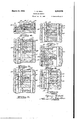
- FIG. 1 is a side elevational view showing a motor vehicle engine and power transmission equipped with my invention.
- Fig. 2 is a longitudinal sectional elevational view through the main clutching mechanism.
- Fig. 3 is a similar view through the change speed transmission.
- Fig. 4 is a detail enlarged view of the blocker clutch as seen in Fig. 3.
- Fig. 5 is a sectional plan view illustrated as a development according to line 5-5 of Fig. 4, the automatic clutching sleeve being released.
- Fig. 6 is a similar view showing the automatic clutching sleeve in its intermediate shift position during the drive blocking condition.
- Fig. 7 is a similar view showing the automatic clutching sleeve in its coasting relationship from the Fig. 6 showing, the clutching sleeve being unblocked during coast for its clutching movement.
- Fig. 8 is a similar view showing the automatic clutching sleeve ln full clutching engagement.
- Fig. 9 is a view similar to Fig. 5 but showing the automatic clutching sleeve in its other intermediate shift position during the coast blocking condition.
- Fig. 10 is a diagrammatic view of my invention in conjunction with the control mechanism for the automatic clutching sleeve, the latter being shown in its released position.
- Fig. 11 is a similar view in another position of certain of the parts.
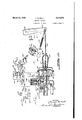
- Fig. 12 is a sectional elevational view showing the throttle retarding device and my control therefor.
- Fig. 13 is a detail elevational view taken as indicated by line
- Fig. 14 is a diagrammatic view generally corresponding to Fig. 10 but illustrating a modiled form of my invention.
- Fig. 15 is a View of the Fig. 14 control system illustrating certain -of the parts in another position of operation.
- Fig. 16 is an elevational view showing diagrammatically a modified control system for my throttle retaining device.
- Fig. 1'? is a sectional elevational View showing the distributer of Fig. 16 with parts broken away to illustrate my control.
- Fig. 18 is a sectional plan view showing the distributer governor.
- Fig. 19 is a sectional view taken generally as indicated by line l9-I9 of Fig. 17.
- A represents the internal combustion engine which drives through fluid coupling B and conventional type of friction main clutch C to the speed ratio transmission D whence the drive passes from output shaft 20 to drive the rear vehicle wheels in the usual manner.
- the engine crankshaft 2l carries the vaned fluid coupling -impeller 22 which in the well known manner drives the vaned runner 23 whence the drive passes through hub 24 to clutch driving member 25.
- This member then transmits the drive, when clutch C is engaged as in Fig. 2, through driven member 26 to the transmission driving shaft 21 carrying the main drive pinion 28.
- a clutch pedal 29 controls clutch C such that when the driver depresses this pedal, collar 30 is thrust forward to cause levers 3
- the primary function of the main clutch C is to enable the driver to make manual shifts in transmission D.
- pinion 28 is in constant mesh with gear 34 which drives countershaft 35 through an overrunning clutch E of the usual type such that when shaft 21 drives in its usual clockwise direction (looking from front to rear) when clutch E will engage to lock gear 34 to countershaft 35 whenever the gear 34 tends to drive faster than the countershaft.
- clutch E will automatically release whereby shaft 21, under certain conditions, may readily drop its speed while countershaft 35 continues to revolve.
- Countershaftv 35 comprises cluster gears 36, 31 and 38 which respectively provide drives in first, third and reverse. Freely rotatable on shaft 20 are the first and third driven gears 39 and 40 respectively in constant mesh with countershaft gears 36 and 31.
- a hub 4I is splined on shaft 20 and carries therewith a manually shiftable sleeve 42 adapted to shift from the Fig. 3 neutral position either rearwardly to clutch with teeth 43 of gear 39 or else forwardly to clutch with teeth 44 of gear 40.
- Sleeve 42 is operably connected to shift rail 45 adapted for-operation by any suitable means under shifting control of the vehicle driver.
- Shaft 20 also carries reverse driven gear 49 fixed thereto.
- a reverse idler gear 41 is suitably mounted so that when reverse drive is desired, idler 41 is shifted into mesh with gears 38 and 46.
- third and reverse speed ratio drives and neutral are under manual shift control of the vehicle driver, the main clutch C being released by depressing pedal 2'9 in shifting into any one of these drives.
- First is obtained by shifting sleeve 42 to clutch with teeth 43, the drive passing from engine A, through fluid coupling B, clutch C and shaft 21 to pinion 28 thence through gear 34 and clutch E to countershaft 35. From the countershaft the drive is through gears 36, 39 and sleeve 42 to shaft 2U.
- Third is obtained by shifting sleeve 42 to clutch with teeth 44, the drive passing from the engine to the countershaft 35 as before, thence through gears 31, 40 and sleeve 42 to shaft 20.
- Reverse is obtained by shifting idler into mesh with gears 38, 46, sleeve 42 being in neutral, the reverse drive passing from the engine to the countershaft 35 as before, thence through gears 38, 41 and 4S to shaft 20.
- Figs. 4 to 9 there is shown the blocking means for controlling clutching shift of sleeve F so as to limit clutching thereof to engine coasting and synchronous relationship of the clutching parts. aseries of pairs of what may be termed long fand short teeth 50, 5
- blocker 52 has, at suitable locations, a drive lug 54 engaged in a slot 55 of gear 40.
- the blocker is urged under light energizing pressure of spring 56 into constant frictional engagement at 51 with pinion 28 so that the blocker tends to rotate with pinion'28 within the limits afforded by the travel of lug 54 ciroumferentially in slot 55.
- the transmission is provided with suitable prime mover meansfor controlling shift of sleeve F along with several control means.
- a pressure fluid operated motor G utilizing air pressure for its operation.
- this motor is arranged to operate by the vacuum in the intake manifold system of the engine under control of electromagnetic means illustrated in the form of a solenoid H.
- Rod 68 has a. series of detents 10. 1
- rod 68 may move rearwardly sufficiently to close gap 16 at the lost-motion between rod portion 89 and rod 62, this movement causing switch 18 to close and ground the ignition system whereupon spring 61 may then cause further movement of rod 68 and rod 62 to release sleeve F, the switch 16 then opening by detent 10 to restore the ignition system.
- the vacuum supply to chamber 14 is under control of solenoid H which comprises an armature plunger 80 having valving parts 8
- solenoid H is energized thereby raising plunger 80 against spring 83 to seat valve 82 and shut ofi the vacuum supply to chamber 14 and at the same time unseat valve 8
- spring 83 lowers plunger 80 thereby seating valve 8l to shut oft' vent 86 and open valve 82 as in Fig. 11 thereby opening chamber 14 to the engine intake manifold K through passage 84, chamber 86', and pipe 81.
- a certain lost motion is provided.. between plunger 80 and the inwardly bent finger 13 of latch 13 so that when the plunger moves downwardly the latch may subsequently catch at detent 12 when vacuum operates piston 66, the parts then, remaining in the Fig. 11 position independently of vacuum in chamber 14 until solenoid H is energized to release the latch and vent chamber 14.
- a governor J Driven from countershaft gear 88 is a governor J of any suitable type, this governor operating a sleeve 89 outwardly along its drive shaft 90 as the car speed reaches a predetermined point, the break-away being under control of a detent 9
- the sleeve 89 has a shoulder 92 engaged by the swinging switch piece 93 of the governor switch 94.
- is engaged and switch 94 is closed.
- the governor eventually reaches its critical speed and detent 9
- the governor spring 95 restores the parts to the Fig. l position and by proportioning the various parts it is obvious that switch 94 may be made to function at desired speed proportionate to car travel.
- the governor may bemade to open switch 94 during car acceleration in first and third respectively at approximately 7 and 15 M. P. H. (miles per hour), the switch 94 closing on stopping the car in direct and second at approximately '1 and 3 M. P. H. respectively.
- the interrupter switch 18 is in series with switch 94 and also by ⁇ another circuit with the kick-down switch to be presently described, a branch conductor
- the engine ignition system part of which is shown in Fig. 10, extends from battery
- kick-down solenoid circuit Another electrical circuit, referred to as the kick-down solenoid circuit, is arranged, similar in some respects to the governor solenoid circuit,
- solenoid H for controlling solenoid H so that when the engine throttle is approximately wide open the solenoid may be energized to release latch 13 thereby allowing spring 61 to take up gap 16 and, in succession, ground the engine ignition system, release sleeve F, restore the ignition system, and by reason of the open throttle cause the engine to quickly increase its speed to engage clutch E so as to drive the car in either first or third depending on whether the kick-down mechanism was operated while driving in second or fourth respectively.
- 0 is a push plunger self-releasing type of switch operated by push plunger
- the accelerator pedal 50 is yieldingly urged to its throttle closing position by the usual spring 3, this pedal operating through link
- Secured to this shaft is the usual throttle valve
- 5 is pivotally mounted at 2
- This accelerator pedal release opens switch
- the sleeve 42 may be left in its high range and all stops and starts made without further shifting. This is possible owing to slippage in the fluid coupling when stopping the car for a traiclight and is practicable because the fludcoupling allows high engine torque for favorable car acceleration and because the governor J always directs a downshift by causingl sleeve F to release ⁇ on bringing the car to rest. Thus there is automatically provided a favorable torque-multiplying gearing for starting, as in third. Just as in first, the drive is free-wheeling ln third below car speeds which otherwise would cause the governor switch 94 to open.
- the sleeve F is alsodisengaged bya full depression of the accelerator Apedal 50 at the will of the driver while governor switch 94 is open,
- this kick-down control being especially beneficial to enable the driver to quickly step-down the transmission ratio for more favorable torque drive as in passing a car on the road or in climb-
- the illustrated driver operable means is preferably arranged for control by depressing movement is retarded sufficiently so that a condition of equilibrium is reached in the fluid coupling and in the engine intake system whereupon the throttle is then fully closed for conventional engine idling without danger of stalling the engine.
- the step-down will occur as a natural result of manipulating the accelerator pedal for maximum power output.
- the pedal may either be arranged to provide this step-down as the engine throttle approaches its wide open position as illustrated or subsequently to the throttle reaching its wide open position by providing a mechanism, such as illustrated Neracher et al., application, which allows the accelerator pedal to overtravel its throttle actuating range into a secondary range. Therefore, when the accelerator pedal is fully depressed, at times when switch 94 is open and the car is being driven in fourth or second, the kickdown solenoid circuit is thereby established causing momentary interruption of the ignition system accompanied by step-down in the transobjectionable length of time for the step-up and free-wheeling elimination to occur.
- I have therefore provided novel means to automatically render the dashpot inoperative at times when there is no danger of engine stalling under theaforesaid conditions and in the illustrated transmission system I preferably employ the same governor J to control the Vdashpot action.
- governor J directs clutching of sleeve F the dashpot is put out of action thereby insuring rapid speed ratio step-up and free-Wheeling elimination as soon as the accelerator pedal is released, this function taking place without any danger of engine stalllng'because sleeve F, ⁇
- a dashpot L preferably of the fluid type, having a cylinder
- a movable dashpot element in the form of a piston
- 21 In order to control the throttle valve by piston
- yieldingly acts to raise piston
- dashpot L takes' place at engine speeds corresponding to car speeds sufllciently low to maintain the governor switch 94 closed.
- the dashpot L is rendered inoperative by either the following means.
- 42 axially aligned with rod
- This solenoid ismounted on a bracket
- 48 operates, when the solenoid M is de-energized, to
- relay N When the car is being driven at low speeds such that governor switch 94 is closed, then relay N isv energized as in Fig. 10 and the solenoid M is de-energized as in-Fig. l2 thereby causing spring
- This is brought about by the following relay circuit: ground 96 to switch 84 thence through conductors91 and
- the dashpot L is rendered ineiective to retard closing of the throttle valve as aforesaid but is again brought into action in response to closing of switch 94 as soon as the car speed is sufficiently retarded.
- the accelerator pedal 50' is shown at about half throttle opening position.
- the dashpot L is automatically operative when there is danger of engine stalling and when it does not slow up the transmission coast speed change. and free-wheeling elimination which operate only above the critical speed of governor J.
- governor J acts to open switch 94
- the dashpot L is rendered ineffective and the step-up in drive incident to clutching movement of sleeve F and the elimination of free-wheeling is expedited without interference by the dashpot L.
- the engine is used more efficiently as a brake,-by reason of the elimination of the dashpot action because when the accelerator pedal is released forecasting against the engine, the throttle valve immediately closes.
- the wiring diagram for the Fig. 14 embodiment is generally similar to Fig. 10 although somewhat simplified because in Fig. 14 solenoid M' is interposed in the aforesaid conductor
- the solenoid M is now in a circuit in series with governor switch 94 as follows ground 96, switch v64 through conductor 91 to solenoid M and conductor
- the control functions of the dashpot and transmission as a whole are identical with the Fig. embodiment and need not be repeated.
- 66 is by reason of a plurality of pins
- 61 yieldingly urges plate
- This embodiment of 4Figs. 16 to 19 is especially ⁇ v beneficial in cars equipped with a. slip-drive, such as a fluidcoupling, or a releasable drive such as an overrunning, clutch but maybe used to advantage in practically any driving system.
- a slip-drive such as a fluidcoupling
- a releasable drive such as an overrunning, clutch
- the weights have an.
- 64 Driven with and fixed to shaft
- 66 is a plunger
- 12 have -switch Aterminals adjacent piece
- 65 movesA upwardly by the action of spring
- 10 also then moves plunger
- dashpot means operable to retard the throttle closing movement
- governor means operable to ⁇ render the dashpot means ineffective to retard the throttle closing movement
- dashpot means operable to retard only the last part of the throttle closing movement
- electro-magnetically controlled means operable to render the dashpot means ineffective to retard the last part of the throttle closing movement
- a motor Vehicle drive comprising an engine having a throttle adapted for opening and closing movements, means operable to retard only the last part of the throttle closing movement, and means operable in response to predetermined speed of travel of the vehicle to render the retarding means ineffective to retard the last part of the throttle closing movement.
- a motor vehicle drive comprising an engine having a throttle adapted for opening and closing movements, means operable to retard only the last part of the throttle closing movement, electro-magnetically controlled means operable to selectively render the retarding means either operable as aforesaid or ineffective to retard the last part of the throttle closing movement, and means operable in response to predetermined speed of travel of the vehicle to control energization of said electro-magnet.
- a motor vehicle-drive comprising an engine having a throttle adapted for opening and closing movements, means operable to retard only the last part of the throttle closing movement, electro-magnetically controlled means operable to selectively render the retarding means either operable as aforesaid or ineffective to retard the last part of the throttle closing movement, switch means operable to control energization of said electro-magnet, and means operable in response to predetermined speed of travel of the vehicle for operating said switch means.
- a motor vehicle drive comprising an engine having a throttle adapted for opening and closing movements, means operable to retard only the last part of the throttle closing movement, electro-magnetically controlled means operable in response to energization of the eleconly the last part of the throttle closing movement, electro-magnetically controlled means operable in response to energization of the electromagnet to render the retarding means inelective to retard the last part ofthe throttle closing movement and to render the retarding means operable as aforesaid in response to (ie-energization of the electro-magnet, an electrical relay operable to effect energization and de-energ'zation of the electro-magnet, switch means operable to control operation of the relay, and means operable in response to predetermined speed of travel of the vehicle for controlling operation of said switch means.
- a motor vehicle drive comprising an engine having a throttle adapted for opening and closing movements, means operable to retard only the last part of the throttle closing movement, electro-magnetically controlled means operable in response to de-energization of thc electro-magnet to render the retarding means ineffective to retard the last part of the throttle closing movement and to render the retarding means operable as aforesaid in response to energization of the electro-magnet, and means operable in response to predetermined speed of travel .of the vehicle to effect energization and cie-energization of the electro-magnet.
- a motor vehicle drive comprising an engine having a throttle adapted for opening and closing movements, means operable to retard only the last part of the throttle closing movement, electro-magnetically controlled means operable in response to de-energization of the electro-magnet to render the retarding means ineffective to retard the last part of the throttle closing movement and to render the retarding means operable asaforesaid in response to energization of the electro-magnet, switch means operable to control energization of said electro-magnet, and means operable in response to predetermined speed of travel of the vehicle for operating said switch means.
- a variable speed ratio transmission comprising means operable to effect change in the speed ratio drive between the engine and vehicle, change-speed control means operable to control operation of said speed ratio change means, and -means operable underv control of said change-speed control means for selectively rendering the throttle retarding means either operable as aforesaid or ineffective to retard the last part of the throttle closing movement.
- a variable speed ratio transmission comprising means operable to effect change in the speed ratio drive between the engine and vehicle, change-speed control means operable in response to retardation of the engine speed to control operation of said speed ratio change means, and means operable under control of said change-speed control means for selectively rendering the throttle retarding means either operable as aforesaid or ineffective to retard the last part of the throttle closing movement.
- a variable speed ratio transmission comprising means operable to effect change in the speed ratio drive between the engine and vehicle, change-speed control means operable in response to predetermined speed of travel of the vehicle to control operation of said speed ratio change means, and means operable under control of said change-speed control means for selectively rendering the throttle retarding means either operable as aforesaid or ineffective to retard the last part of the throttle closing movement.
- variable speed ratio transmission comprising means operable to effect change "in the speed ⁇ 'atiodrivebetweenethe engine and vehicle, change-speed control means operable in response to predetermined speed of vehicle travel for controlling'u operation of said speed ratio change means upon retarding the engine speed,
- a drive for amotor vehicle having an eny gine provided with a throttle adapted for opening'and closing movements, means operable to retard only the last part of the throttle closing movement, a variable speedV ratio transmission comprising Vmeans operable to effect step-up change in .the 'speed ratio drive between the engine andjvehicle when the'engine speed is retarded while the vehicle is travelling at or above a predetermined speed, change-speed.
- control means operable to control operation of said speed.
- Y ratio changei in response to predetermined speed of travel of the vehicle, and means operable under control of said change-speed control means forl rendering .
- the throttle retarding means ineifective to retard the last part of the throttle Y closing movement when the vehicle attains the aforesaid predetermined speed.
- change-speed control means operablejto control operation of saidtwo-way drive means in response to predetermined speed of travel of the vehicle when driven by said one-way drive means
- slip-drive means for transmitting vdrive from the engine to the vehicle, means operable 'to-retard closing movement of the throttle thereby to prevent stalling oi the engine, and means operating automatically to control operation of said throttle retarding means such that at relatively low engine speeds, giving rise to engine stalling tendency, said retarding means operates as aforesaid and at relatively high engine speeds; free from engine, stalling tendency, said retarding meansis rendered ineffective to retard throttle closing movement.
- a drive for a motor vehicle having an engine provided with'a throttle adapted for opening and closing movements; drive means for transmitting drive relatively between the-engine and thefvehicle, said' drive means including a fluid medium through which said drive is transmitted; means operable to retard closing movement of the throttle thereby to preventI stalling of the engine; and means operating automatically vto control operation of said throttle retarding drive'tov vehicle coast at relatively high vehicle and engine speeds which are relatively freer from engine stalling tendency,jsaid retarding means is rendered ineffective to retard throttle closing,
Landscapes
- Engineering & Computer Science (AREA)
- Chemical & Material Sciences (AREA)
- Combustion & Propulsion (AREA)
- Mechanical Engineering (AREA)
- General Engineering & Computer Science (AREA)
- Control Of Throttle Valves Provided In The Intake System Or In The Exhaust System (AREA)
Description
March 23', 1943. f. M. BALL '2,314,570-
THROTTLE CONTROL Filed oct. 9, 1940 e sheets-sheet 1 IN ToR March 23,1943. T, M BALL 2,314,570
THROTTLE CONTROL Filedv Oct. 9, 1940 6 Sheets-Sheet 2 INVENToR ATTRNEYS.
March 23, 1943. T. M'. BALL THROTTLE CONTROL Filed Oct. 9, 1940 6 Sheets-Sheet 3 INVENTOR ff/md5 Mdzz. M
'ATTORNEY6- March 23, 1.943. T M BALL.y
' THROTTLE 'CONTROL Filed oct. 9, 1940 esmas-sheet 4 INVENTOR Epo/d'5 EQ/Z @al ATTORNEYS. l
March 23,1943. T. M. BALL u 2,314,570
THROTTLE. cNTRoL Filed Oct. 9, 1940 6 Sheets-Sheet 5 ATTo'RNEYs.
March 23,` 1943.
T. M. BAUQ 2,314,570
THROT'ILE CONTROL Filtd Ont. 9, 1940 6 Sheets-Sheet 6 Patented Mar. 23 1943 y THROTTLE CONTROL Thomas M. Ball, Detroit, Mich., assignor to Chrysler Corporation, Highland Park, Mich., a corporation o'f Delaware Application October 9,'194'0, Serial No. 360,476
22 Claims.
This invention relates to throttle control devices especially in conjunction with motor vehicles.
It is well known at this time that internal combustion engines have a tendency to stall when, at low vehicle driving speeds, the driver suddenly releases the accelerator pedal to allow the throttle valve to suddenly close. This characteristic is especially pronounced in motor vehicles equipped with a fluid coupling through which the drive is taken. `Not only does the uid coupling allow the engine to stall even though the car is travelling at a low speed, by reason of the inherent slip in the fluid coupling, but the action of the iiuid in the coupling incident to change from drive to coast when the driver releases the accelerator pedal accentuates the tendency for the engine to stall. At relatively high speed the iluid coupling acts to prevent stalling of the engine and also at this time the engine does not tend to stall.
Heretofore', in motor vehicles equipped with fluid couplings, free-wheeling clutches, or other devices which release the engine from the car ground wheels when the accelerator pedal is released, or in vehicles without any release device wherein the engine stalling tendency at low speed is especially pronounced, such vehicles have been equipped with a dashpot or similar vretarding device for controlling the last part of throttle closing Imovement independently of the accelerator pedal. Thus, while the accelerator pedal may be suddenly released, the throttle valve has its iinal closing movement retarded so thatv the fuel supply system and other factors which are disturbed and which give rise to engine stalling have an opportunity to become balanced or adjusted to the coast conditions whereupon the throttle valve is allowed to fully close.
The foregoing throttle retarding devices have the disadvantage that at relatively high speeds of the engine and car, the full eiect of utilizing the engine ras a brake, when the accelerator pedal is released, cannot be realized because the throttle valve does not immediately close and the engine does not immediately tend to drop to its idling speed corresponding to fullyv closed throttle. In cars equipped with free-'wheeling devices, there-is usually provided means for automatically rendering vthe free-wheel inoperative above a predetermined car speed as by automatically bringing a two-way drive into action so that the aforesaid engine braking is likewise not fully used in these driving systems when the throttle retarding device is employed. y There is also a further objection to the use of the throttle control devices commonly heretofore employed in conjunction with the aforesaid free-wheel systems and in conjunction with transmission systems incorporating a change speed, usually a step-up in the speed ratio drive, brought into action by releasing the accelerator pedal so as to allow the engine to coast down to synchronize the speeds of the drive control parts. In such systems theA throttle control acts to'increase the time for bringing Vthe change speed into operation or for rendering the freewheel 'inoperative because the engine drops its speed much more slowly than where the throttle control device is not employed.
It is an object of my invention to providev means, preferably automatically acting, for bringing the throttle control device into action at low speeds and for eliminating the throttle control device at higher speeds where it is not needed and where it is a detriment from the standpoints of engine braking, free-wheel elimination, speed ratio change incident to engine coast or any of these factors alone or together. By reason of my control arrangement, the dashpot control device is also protected from unnecessary operation at times when it is not needed thereby increasing its life and making it possible to employ less expensive parts. My control on the action of the throttle control, when automatically operativa'may be made to operate as a function of engine speed or car driving speed. Indriving systems incorporating speed lratio change under speed responsive control, Ipreferably employ the same speed control for controlling the throttle retarding device, especially in those systems wherein the engine has a tendency to stall only at speeds below the speed of operation of the speed ratio change. If this is not convenient or desired, then a separate speed responsive control may be provided for thethrottle retarding device.
Further objects and advantages of my invention will be more apparent from the following illustrative embodiment thereof, reference being had to the accompanying drawings in which: Fig. 1 is a side elevational view showing a motor vehicle engine and power transmission equipped with my invention.
Fig. 2 is a longitudinal sectional elevational view through the main clutching mechanism.
Fig. 3 is a similar view through the change speed transmission.
Fig. 4 is a detail enlarged view of the blocker clutch as seen in Fig. 3.
Fig. 5 is a sectional plan view illustrated as a development according to line 5-5 of Fig. 4, the automatic clutching sleeve being released.
Fig. 6 is a similar view showing the automatic clutching sleeve in its intermediate shift position during the drive blocking condition.
Fig. 7 is a similar view showing the automatic clutching sleeve in its coasting relationship from the Fig. 6 showing, the clutching sleeve being unblocked during coast for its clutching movement.
Fig. 8 is a similar view showing the automatic clutching sleeve ln full clutching engagement.
Fig. 9 is a view similar to Fig. 5 but showing the automatic clutching sleeve in its other intermediate shift position during the coast blocking condition.
Fig. 10 is a diagrammatic view of my invention in conjunction with the control mechanism for the automatic clutching sleeve, the latter being shown in its released position.
Fig. 11 is a similar view in another position of certain of the parts.
Fig. 12 is a sectional elevational view showing the throttle retarding device and my control therefor.
Fig. 13 is a detail elevational view taken as indicated by line |3-I3 of Fig. 12.
Fig. 14 is a diagrammatic view generally corresponding to Fig. 10 but illustrating a modiled form of my invention.
Fig. 15 is a View of the Fig. 14 control system illustrating certain -of the parts in another position of operation.
Fig. 16 is an elevational view showing diagrammatically a modified control system for my throttle retaining device.
Fig. 1'? is a sectional elevational View showing the distributer of Fig. 16 with parts broken away to illustrate my control.
Fig. 18 is a sectional plan view showing the distributer governor.
Fig. 19 is a sectional view taken generally as indicated by line l9-I9 of Fig. 17.
While my control may be employed in conjunction With various types and arrangements of mechanisms and devices, I have illustrated the principles of my invention in connection with a motor vehicle transmission of the type in which speed ratio. change occurs in response to engine retardation. It is desirable to illustrate one such driving system in order to describe the functioning of my control, when used in conjunction with a transmission of this type, and to this end I have shown certain salient parts of the transmission system which is` more fully described and claimed in the copending application ofA Carl A. Neracher et al., Serial No. 335,310, flled May 15, 1940.
In the drawings A represents the internal combustion engine which drives through fluid coupling B and conventional type of friction main clutch C to the speed ratio transmission D whence the drive passes from output shaft 20 to drive the rear vehicle wheels in the usual manner.
The engine crankshaft 2l carries the vaned fluid coupling -impeller 22 which in the well known manner drives the vaned runner 23 whence the drive passes through hub 24 to clutch driving member 25. This member then transmits the drive, when clutch C is engaged as in Fig. 2, through driven member 26 to the transmission driving shaft 21 carrying the main drive pinion 28. A clutch pedal 29 controls clutch C such that when the driver depresses this pedal, collar 30 is thrust forward to cause levers 3| to release the clutch driving pressure plate 32 against springs 33 thereby releasing the drive between runner 23 and shaft 21. The primary function of the main clutch C is to enable the driver to make manual shifts in transmission D.
Referring to the transmission, pinion 28 is in constant mesh with gear 34 which drives countershaft 35 through an overrunning clutch E of the usual type such that when shaft 21 drives in its usual clockwise direction (looking from front to rear) when clutch E will engage to lock gear 34 to countershaft 35 whenever the gear 34 tends to drive faster than the countershaft. However whenever this gear 34 tends to rotate slower than the countershaft then clutch E will automatically release whereby shaft 21, under certain conditions, may readily drop its speed while countershaft 35 continues to revolve.
First, third and reverse speed ratio drives and neutral are under manual shift control of the vehicle driver, the main clutch C being released by depressing pedal 2'9 in shifting into any one of these drives.
First is obtained by shifting sleeve 42 to clutch with teeth 43, the drive passing from engine A, through fluid coupling B, clutch C and shaft 21 to pinion 28 thence through gear 34 and clutch E to countershaft 35. From the countershaft the drive is through gears 36, 39 and sleeve 42 to shaft 2U.
Third is obtained by shifting sleeve 42 to clutch with teeth 44, the drive passing from the engine to the countershaft 35 as before, thence through gears 31, 40 and sleeve 42 to shaft 20.
Reverse is obtained by shifting idler into mesh with gears 38, 46, sleeve 42 being in neutral, the reverse drive passing from the engine to the countershaft 35 as before, thence through gears 38, 41 and 4S to shaft 20.
Slidably splined on teeth 48 carried by gear 40 l is the automatic clutching sleeve F which, under certain conditions, is adapted to shift forwardly to clutch with teeth 49 carried by pinion 23 `thereby positively clutching shaft 21 directly to engine coast, sleeve F being prevented from clutching during that condition known as engine I drive as when the engine is being speeded up under power.
When driving in first, second is obtained by the driver releasing the usual accelerator pedal 50 thereby closing the engine throttle valve and allowing the engine to coast down. When this occurs, the engine along with shaft 21, pinion 28 and gear 34 all slow down while shaft .".iiA along with gears 39 and 36 continue their speeds by accommodation of clutch E which now overruns. The engine slows down until teeth 49 are brought to approximate synchronism with sleeve F which thereupon automatically shifts to clutch with teeth 49 resulting in a two-way drive for second as follows: pinion 28 through sleeve F to gear 40 thence through gears 31, 36 and 39 to sleeve 42 and shaft 20, the clutch'E overrunning. First is a free-wheeling drive,. by reason of overrunning clutch E, until sleeve F shifts forwardly accompanied by engine coast to bring about the aforesaid synchronous condition.
When driving in third, fourth or direct is obtained just as for second by driver release of the accelerator pedal and resulting shift of sleeve F" to clutch with teeth 49 when these parts are synchronized by reason of the engine-coasting down from the drive in third. Third is a freewheeling drive, by reason of overrunning clutch E, until sleeve F shifts forwardly accompanied by engine coast to bring about the aforesaid synchronous condition. The direct drive is a two-way drive as follows: pinion 28 through sleeve Fto gear 40 thence directly through sleeve 42- to shaft 20, clutch E overrunning as before.
Referring to Figs. 4 to 9 there is shown the blocking means for controlling clutching shift of sleeve F so as to limit clutching thereof to engine coasting and synchronous relationship of the clutching parts. aseries of pairs of what may be termed long fand short teeth 50, 5| certain of which may be A blocker ring 52.
bridged or joined together. is provided with blocking teeth 53 which either lie in the path' of forward shift of teeth 50 or 5| or else between these teeth to allow clutching shift of sleeve F. Thus, blocker 52 has, at suitable locations, a drive lug 54 engaged in a slot 55 of gear 40. The blocker is urged under light energizing pressure of spring 56 into constant frictional engagement at 51 with pinion 28 so that the blocker tends to rotate with pinion'28 within the limits afforded by the travel of lug 54 ciroumferentially in slot 55.
During drive in first and third, the speed of shaft 21 exceeds the speed of gear 40 so that,
if sleeve F is fully released, the parts will be po' Sleeve F is provided with.
sitioned as in Fig. 5 wherein the blocker leads the sleeve F thereby positioning blocker teeth 53 axially in alignment with the short teeth 5I.
is reduced in speed to that of sleeve F slight further drop in the speed of pinion 2.8 for a fraction of a revolution below the speed of sleeve F will cause blocker 52 to rotate ,slightly relativeto sleeve F until blocker teeth 53 strike the adjacent sides of long teeth 50 as in Fig. '7 thereby limiting further reduction in speed of the blocker relative to sleeve F. At this time the sleeve F is free to complete its forward clutching shift with teeth 49, as in Fig. 8, the blocker teeth 53 passing between adjacent long and short teeth 50, 5I. With the sleeve F thus clutched during engine coast, a two-'way drive is established in second or fourth depending on whether the manually shiftable sleeve F was set for first or third just prior to the clutching shift of sleeve F.
In the event that sleeve F is vurged forwardlyv from its Fig. 5 position at a time when the gear 40 is rotating faster than pinion 28, then the blocker 52 will lag behind the sleeve and will be blocked by engagement of long teeth 50 with the blocker teeth 53 as shown in Fig. 9. This is referred to as the coast blocking condition. If now the engine is speeded up by the driver depressing the acceleratori pedal in the usual manner, then the engine and blocker52 rotate forwardly and blocker teeth 53 move over to the Fig. .6 drive blocking position thereby jumping the gap between teeth 50 and 5I. This is the primary reason for providing the long and short teeth whereby sleeve F clutches only from the drive blocking condition followed by engine coast which protects-the teeth and avoids harsh clutching effects on the passengers and transmission mechanism. On accelerating the engine from the Fig. 9 coast blocking condition, the engine comes up to a speed limited by engagement of the overrunning clutch E for driving in either first or third depending onthe setting of the manually shiftable sleeve 42. Then on releasing the accelerator pedal the sleeve F will synchronously clutch with teeth 49 during coast to stepup the drive to either second or fourth as aforesaid.
The transmission is provided with suitable prime mover meansfor controlling shift of sleeve F along with several control means. Referring particularly to Figs. 10 and 11. there is illustrated a pressure fluid operated motor G utilizing air pressure for its operation. For convenience this motor is arranged to operate by the vacuum in the intake manifold system of the engine under control of electromagnetic means illustrated in the form of a solenoid H.
Forward shift of sleeve F is effected, under control of motor G, by reason of a spring 58 xed at one end and exerting a pull on lever 59 which is connected to sleeve F through the crossshaft 60 and shifter yoke 6|. Pivoted to the lower end of lever 59 is a follower rod 62 guided in a support 63 and in the rubber sealing boot 64. carried by cylinder 65 which contains the diaphragm piston 66 urged in a direction to release sleeve F by a spring 61 which is much stronger than spring 58. Diaphragm piston 66 is connected toa leader rod 68 which has a rear extension 69 aligned with rod 62.
Rod 68 has a. series of detents 10. 1| and- 12, the latter cooperating with a latch 13 such that when vacuum is admitted tochamber 14 to cause the piston 66 and rod 68 to assume their Fig. 11 positions, latch 13 under action of rat-trap spring 15 catches on the forward shoulder of detent 12 and holds the parts as in "F.ig. 11. At this time rod portion 69 moves further than rod 62 by the amount of gapv 16, a stop 11 acting on lever 59 limiting forward movement of sleeve F by spring 58.
In order to provide for release ofsleeve F, it is desirable to provide some means 'for momentarily relieving the torque load at the teeth 49 and sleeve F and in thepresent instance I have provided such means as a system of grounding `insure its release by spring 61.
the primary terminal of the usual distributer of the ignition system whereby the engine ignition may be momentarily rendered ineffective thereby unloading the torque at sleeve F sufficiently to This ignition interrupting system is under control of an interrupter switch 18 which is closed by plunger 19 and ball 80' whenever rod 69 moves between the Fig. 10 and Fig. 11 positions by reason of the enlarged rod portion between detents 10, 1|. Detent 1| is so arranged that, with the parts as in Fig. 11 and sleeve F clutched, rod 68 may move rearwardly sufficiently to close gap 16 at the lost-motion between rod portion 89 and rod 62, this movement causing switch 18 to close and ground the ignition system whereupon spring 61 may then cause further movement of rod 68 and rod 62 to release sleeve F, the switch 16 then opening by detent 10 to restore the ignition system.
The vacuum supply to chamber 14 is under control of solenoid H which comprises an armature plunger 80 having valving parts 8|, 82. In Fig. 10 the solenoid H is energized thereby raising plunger 80 against spring 83 to seat valve 82 and shut ofi the vacuum supply to chamber 14 and at the same time unseat valve 8| so as to vent this chamber through passage 84, chamber 85 and vent passage 8B. When the solenoid is deenergized then spring 83 lowers plunger 80 thereby seating valve 8l to shut oft' vent 86 and open valve 82 as in Fig. 11 thereby opening chamber 14 to the engine intake manifold K through passage 84, chamber 86', and pipe 81.
A certain lost motion is provided.. between plunger 80 and the inwardly bent finger 13 of latch 13 so that when the plunger moves downwardly the latch may subsequently catch at detent 12 when vacuum operates piston 66, the parts then, remaining in the Fig. 11 position independently of vacuum in chamber 14 until solenoid H is energized to release the latch and vent chamber 14.
It is deemed preferably to provide a speed control on the energization of solenoid H so as to insure automatic release of sleeve F below a predetermined car speed and automatic engagement of sleeve F above a predetermined car speed. Whenever the car is in forward driving condition the manual sleeve 42 is either shifted rearwardly to the low range or forwardly to the high range so that by driving a governor from the countershaft 35 it is possible to provide a speed control operated proportionate to the speed of travel of the car. Driven from countershaft gear 88 is a governor J of any suitable type, this governor operating a sleeve 89 outwardly along its drive shaft 90 as the car speed reaches a predetermined point, the break-away being under control of a detent 9| if desired.
The sleeve 89 has a shoulder 92 engaged by the swinging switch piece 93 of the governor switch 94. When the car is stationary the detent 9| is engaged and switch 94 is closed. As the car accelerates, the governor eventually reaches its critical speed and detent 9| releases thereby causing switch 94 to open. As the car slows down, the governor spring 95 restores the parts to the Fig. l position and by proportioning the various parts it is obvious that switch 94 may be made to function at desired speed proportionate to car travel. As an example of one arrangement of governor operation and gearing arrangement, the governor may bemade to open switch 94 during car acceleration in first and third respectively at approximately 7 and 15 M. P. H. (miles per hour), the switch 94 closing on stopping the car in direct and second at approximately '1 and 3 M. P. H. respectively.
When switch 94 closes then the solenoid H is energized to vent chamber 14, a governor solenoid circuit being established from ground 96 through switch 94 and conductors 91, 98 to solenoid H thence by conductor 99 to ignition switch |00, ammeter |0|, battery |03 and ground |04. In Fig. 10 the ignition switch is shown closed. When open, as indicated by the dotted line showing, then this circuit is opened.
The interrupter switch 18 is in series with switch 94 and also by `another circuit with the kick-down switch to be presently described, a branch conductor |05 extending between conductor 98 and one terminal'of switch 18, the other terminal being connected by a conductor |06 to the primary terminal of distributer |01 and coil |08 in such manner as to ground and render inoperative the engine ignition system by closing interrupter switch 18.
The engine ignition system, part of which is shown in Fig. 10, extends from battery |03 through the ignition switch |00 and thence by conductor |02 to the coil |08 and distributer |01.
Another electrical circuit, referred to as the kick-down solenoid circuit, is arranged, similar in some respects to the governor solenoid circuit,
l for controlling solenoid H so that when the engine throttle is approximately wide open the solenoid may be energized to release latch 13 thereby allowing spring 61 to take up gap 16 and, in succession, ground the engine ignition system, release sleeve F, restore the ignition system, and by reason of the open throttle cause the engine to quickly increase its speed to engage clutch E so as to drive the car in either first or third depending on whether the kick-down mechanism was operated while driving in second or fourth respectively. 'I'his kick-down solenoid circuit comprises a ground |09 thence by conductor |09 to the kick-down switch ||0 thence by conductor ||l to conductor 98, the rest of this circuit being the same as the governor solenoid circuit through solenoid H, ignition switch |00, ammeter |0|, battery |03 and ground |04.
The kick-down switch ||0 is a push plunger self-releasing type of switch operated by push plunger ||2. The accelerator pedal 50 is yieldingly urged to its throttle closing position by the usual spring 3, this pedal operating through link ||4, lever H5, and link ||6 to move the throttle valve lever ||1 pivoted to shaft ||8. Secured to this shaft is the usual throttle valve ||9 which controls the mixture of air and gasoline at carburetor |20. The lever ||5 is pivotally mounted at 2| and has fixed thereto a second lever ||2 so arranged in relation to plunger ||2 that when the accelerator pedal is fully depressed lever |22 engages plunger 2 and pushes the plunger thereby closing switch l0 and closing the kick-down solenoid circuit. When the accelerator pedal is released, plunger |l2 follows the releasing movement of lever |22 thereby opening switch |0 and opening the kick-down solenoid circuit. Thus, opening and closing operations of switch ||0 occur at the region of full throttle opening and full depression of the accelerator pedal.
In the operation of the mechanism as thus far described, the car at standstill and with ignition switch |00 closed will cause the solenoid H to be energized as in Fig. 10 because governor switch ving a hill.
94 is closed.- Cylinder T 4 is vented andsleeve F.
disengaged. The driver shifts sleeve 42 to either the high or low range and accelerates the car ordinarily above the critical speed of governor J causing switch 94 to open. As vacuum builds up in the engine intake manifold K, plunger 80 now being lowered because switch 94 is open, piston 66: will be operated by vacuum thereby moving rod 68 to its Fig. 1l latched position. As soon as the driver allows the engine to coast, sleeve F will engage teeth 49 synchronously, to step-up the drive to either second or fourth although the step-up will be delayed until engine coast thereby enabling drive in the slower driving ratio of ilrst or third as longf as desired. If the driver releases the accelerator pedal at a car speed below that causing switch 94 to open, then the car will free- Wheel in rst. under control of overrunning clutch E.
If the car -is initially accelerated in rst to a speed above the governor critical speed and the engine then allowed to coast, second will automatically become operative. Then if -the driver shifts sleeve 42 forwardly to the high range, third will of course be skipped and fourth will be obmission speed ratio as aforesaid to third or first as the case'may be. When the driver releases the accelerator pedal, assuming switch 94 is still' open at such time, sleeve F will restore the drive to fourth or second as the engine slows down to unblock sleeve Fat a speed synchronizing teeth 49 with the teeth of sleeve F. This accelerator pedal release opens switch ||0 thereby opening the kick-down solenoid circuit whereupon ohamber 14 is opened to vacuum causing piston 66 to move to its latched position of Fig. l1, spring 58 acting to move sleeve F forwardly.
In the foregoing driving system, there is a tendency of the engine to stall at low speeds viz., at speeds when the governor switch 94 is closed, when the driver suddenly releases the accelerator pedal 50' to call for full throttle closing. This stalling tendency is aggravated by the presence of free-wheeling at clutch E under the conditions aforesaid and more particularly by reason of the use of the fluid coupling B. It is therefore advisable to incorporate in the system a dashpot control on the last part of the throttle closing movement such that this tained because sleeve F will remain engaged.
Ordinarily, especially where the car is equipped with a fluid coupling B, the sleeve 42 may be left in its high range and all stops and starts made without further shifting. This is possible owing to slippage in the fluid coupling when stopping the car for a traiclight and is practicable because the fludcoupling allows high engine torque for favorable car acceleration and because the governor J always directs a downshift by causingl sleeve F to release `on bringing the car to rest. Thus there is automatically provided a favorable torque-multiplying gearing for starting, as in third. Just as in first, the drive is free-wheeling ln third below car speeds which otherwise would cause the governor switch 94 to open.
On bringing the car to a stop in fourth or second, the governor J will close switch 94 thereby energizing solenoid H and. venting chamber 14 which causes spring 61 to thrust rods 68 and 62 rearwardly lto release sleeve F as the Ycar approaches a stop with attendant low torque at the teeth of sleeve F.
The sleeve F is alsodisengaged bya full depression of the accelerator Apedal 50 at the will of the driver while governor switch 94 is open,
this kick-down controlbeing especially beneficial to enable the driver to quickly step-down the transmission ratio for more favorable torque drive as in passing a car on the road or in climb- The illustrated driver operable means is preferably arranged for control by depressing movement is retarded sufficiently so that a condition of equilibrium is reached in the fluid coupling and in the engine intake system whereupon the throttle is then fully closed for conventional engine idling without danger of stalling the engine.
However, when such a dashpot control is incorporated in the system, it acts to increase the time of engine'retardation, compared to retardation time without the dashpot, so that synchronization of sleeve F with teeth 49 is undesirably delayed and the driver is compelled to wait an the accelerator pedal 50 all the way so that.
the step-down will occur as a natural result of manipulating the accelerator pedal for maximum power output. The pedal may either be arranged to provide this step-down as the engine throttle approaches its wide open position as illustrated or subsequently to the throttle reaching its wide open position by providing a mechanism, such as illustrated Neracher et al., application, which allows the accelerator pedal to overtravel its throttle actuating range into a secondary range. Therefore, when the accelerator pedal is fully depressed, at times when switch 94 is open and the car is being driven in fourth or second, the kickdown solenoid circuit is thereby established causing momentary interruption of the ignition system accompanied by step-down in the transobjectionable length of time for the step-up and free-wheeling elimination to occur. I have therefore provided novel means to automatically render the dashpot inoperative at times when there is no danger of engine stalling under theaforesaid conditions and in the illustrated transmission system I preferably employ the same governor J to control the Vdashpot action. Thus, as soon as governor J directs clutching of sleeve F the dashpot is put out of action thereby insuring rapid speed ratio step-up and free-Wheeling elimination as soon as the accelerator pedal is released, this function taking place without any danger of engine stalllng'because sleeve F,`
on clutching, brings about a two-way drive whereby the car drives the engine through the fluid coupling and also because at such time the engine speed is suiiiciently high so that ordinarily there will be no tendency for the engine to stall. Once the dashpot has been rendered inoperative, it preferably remains in this condition for all car speeds above those corresponding to opening of governor switch 94 but as lsoon as the governor switch closes as an incident to retardation of the car, then the dashpot control is rendered operative again. This will guard against engine stalling at low speeds of the engine and is not, objectionable from other viewpoints because at such times it is not desired to engage clutch F as a function of engine retardation.
Referring particularly to Figs. l2 and 13, there is mounted on the carburetor |20 a dashpot L, preferably of the fluid type, having a cylinder |25 adapted to store a quantity of working duid such as oil. Within this cylinder there is fitted a movable dashpot element in the form of a piston |26 carried'by the lower end of a rod |21 which is provided with a main passage |28 freely open downwardly to the lower closed chambered end |30 of cylinder |25. Adjacent the upper end of piston |26 there is a restricted vent passage |29 which controls the rate of downward travel of the piston. 'I'he fluid is stored above the piston and freely enters the dashpot working chamber |30 through passage |28 when the piston moves upwardly by reason of passage inlets |3| under control of a ball check valve |32. When the piston moves upwardly, the ball |32 moves downwardly on the spidered seat |33 and freely allows the fluid to enter inlets |3|, whence the fluid flows past ball |32 and down passage |28 to chamber |30. When the piston moves downwardly, the fluid is forced up in passage |28 causing ball |32 to seat upwardly and thereby preventing escape of the uid at inlets |3|. The fluid must then escape at vent |29 which is of such capacity as to reta-rd the downward stroke of the piston until the aforesaid condition of equilibrium is reached at which there is no danger of the engine stalling.
In order to control the throttle valve by piston |28, rod |21 is connected at its upper end, as at |34, with the offset portion |35 of the reciprocatory lever |38 slidable in a guide |31 and having its lower end shouldered at |38 for engagement by the offset finger |38 of a lever |40 which is xed to the aforesaid throttle-valve shaft ||8 at vthe end opposite to that carrying lever ||1. A spring '|4| yieldingly acts to raise piston |26 so as to position shoulder |38 for engagement by nger |39 during the last portion of throttle valve closing. Thus when the accelerator pedal 50 is released, spring ||3 quickly acts to nearly close the throttle valve whereupon finger |39 engages shoulder |38 and the remainder of the throttle-closing `movement is under the delayed control of dashpot L. When the accelerator pedal is depressed,lever |40 swings clockwise as seen in Fig. 13 away from shoulder |38 so that the throttle valve opens without restriction from dashpot L, spring |4| then raising piston |26 and shoulder |38 into position ready to again retard the inal closing movement of the throttle valve when the accelerator pedal is released.
The foregoing operation of dashpot L takes' place at engine speeds corresponding to car speeds sufllciently low to maintain the governor switch 94 closed. When the governor J operates to open this switch then the dashpot L is rendered inoperative by either the following means.
In Figs. to 13, I have provided an armature plunger |42 axially aligned with rod |21 and slidably disposed in the windings |43 so as to form therewith an electro-magnet in the form of a solenoid M. This solenoid ismounted on a bracket |44 extending from and above the cylinder cover |45, the lower end portion ofyplunger |42 being guided in this cover. A spring |48 operates, when the solenoid M is de-energized, to
-' required for the engine to slow down tp synchronize teeth 49 with sleeve F, as compared with the time required if the dashpot L delayed the last part of throttle-closing. This not only expedites the change speed functioning of transmission D and the elimination of' free-wheeling but also insures more efficient use of the engine as a brake whenever the accelerator pedal is released at speeds causing the governor switch I4 to open.
The governor dashpot circuit for controlling the dashpot L is as follows. Interposed in a conductor |41, which extends between the governor switch |00 and conductor 91 such that conductor |41 is under control of the ignition switch, is the coil |48 of a relay N. This coil controls a swinging switch piece |49 which is electrically connected to the conductor |41 such that when the relay is energized. the switch piece |49 is in the Fig. 10 position out of contact with the other switch piece |50 and when de-energized the switch piece |49 swings into engagement with |50 as in Fig. 1l. The switch piece |50 is connected by conductor |5| to solenoid M and thence to ground |52.
When the car is being driven at low speeds such that governor switch 94 is closed, then relay N isv energized as in Fig. 10 and the solenoid M is de-energized as in-Fig. l2 thereby causing spring |46 to raise plunger |42 and allowing the dashpot L to act to retard the last portion of throttle valve closing. This is brought about by the following relay circuit: ground 96 to switch 84 thence through conductors91 and |41 through coil |48 of relay N to ignition switch |00 and thence through ammeter |0| and battery |03 to ground |04.
When the -car speed is such that governor J acts to open the governor switch 94, then the relay circuit is broken and switch piece |49 contacts with switch piece |50 thereby establishing the folowing circuit: ground |52 to solenoid M thence by conductor |5| through switch pieces |50 and |49 through conductor |41 to ignition switch |00 and out at ground |04 as before. When this circuit is established, plunger |42 moves downwardly against the action of springs |46 and |4| to force piston |28 to the end of its throttle retarding stroke and keeps it there as long as the governor switch 94 remains open. In such position the dashpot L is rendered ineiective to retard closing of the throttle valve as aforesaid but is again brought into action in response to closing of switch 94 as soon as the car speed is sufficiently retarded. In the drawings, the accelerator pedal 50' is shown at about half throttle opening position.
From the foregoing arrangement it will be apparent that the dashpot L is automatically operative when there is danger of engine stalling and when it does not slow up the transmission coast speed change. and free-wheeling elimination which operate only above the critical speed of governor J. However as soon as governor J acts to open switch 94, then the dashpot L is rendered ineffective and the step-up in drive incident to clutching movement of sleeve F and the elimination of free-wheeling is expedited without interference by the dashpot L. Also at the higher speeds the engine is used more efficiently as a brake,-by reason of the elimination of the dashpot action because when the accelerator pedal is released forecasting against the engine, the throttle valve immediately closes.
Referring now to Figs. 14 and 15 I have provided an arrangement for the same car driving system which does not require the use of the relay N of Fig;v 10. In this modied arrangement I employ the same dashpot L as before but now the solenoid M' has its armature plunger |53 raised, whenthe solenoid is energized, against the action of a spring |54 as in Fig. 14. This is the low speed condition at which time dashpot L functions as before. When the solenoid M is de-energized at high speeds, spring |54 lowers plunger |53 thereby causing the dashpot piston |26 to move to the limit of its downward stroke and to remain there until the solenoid is again energized. y
The wiring diagram for the Fig. 14 embodiment is generally similar to Fig. 10 although somewhat simplified because in Fig. 14 solenoid M' is interposed in the aforesaid conductor |41instead of the relay N. Thus the solenoid M is now in a circuit in series with governor switch 94 as follows ground 96, switch v64 through conductor 91 to solenoid M and conductor |41 to the ignition switch and thence to ground |04 as before.. Therefore in this somewhat simplified arrangement the solenoid M willbe energized at low speeds when governor switch 94 is closed, and de-energized at high speeds when the governor switch is open. The control functions of the dashpot and transmission as a whole are identical with the Fig. embodiment and need not be repeated.
Referring now 'to'the embodiment of my invention illustrated in Figs. 16 to 19 I have provided an arrangement for controlling the throttle dashpot in response to engine speed. This may be ac complished in many ways by providing suitable speed responsive control means operated as a function of engine speed. In order to avoid the addition ofa separate governing means I have provided a novel arrangement utilizing the gov- (Fig. 19) such that at the desired engine speed the movement of this weight will cause pin |65 to move downwardly in plate |64 and stay in such position forl all higher speeds. The lower end of pin |65 engages a second plate |66 which always rotates with plate |64 and hence with shaft |51 but is capable of limited axial movement on this shaft. One way to drive plate |66 is by reason of a plurality of pins |66a. fixed at one end to plate |64 and having their other ends loosely and slidably engaging openings in plate |66. A spring |61 yieldingly urges plate |66 and pin |65 upernor which is a part of a well-known distributer to control the dashpot in additionto performing v its Well-known functions of advancing and retarding the spark in accordance with engine speed.
This embodiment of 4Figs. 16 to 19 is especially`v beneficial in cars equipped with a. slip-drive, such as a fluidcoupling, or a releasable drive such as an overrunning, clutch but maybe used to advantage in practically any driving system.
weights |58 pivoted at |59. The weights have an.
ipstanding pin |60 engaging slots |6| of a plate |62 which carries the cam |63 for controlling the firing order of the engine cylinders in well-known manner. The pins |59 project upwardly from plate |64 to drive the weights |58 respectively. As the engine speed increases, the weights |58 move outwardly on their pivots against the restoring action of springs |58a and rotate plate |62 and cam |63 relative to the drive shaft |51 so as to advance the spark. I have provided an arrangement which utilizes weights |58 to control the throttle dashpot at a predetermined desired speed of the engine such as around 600 to '700 R. P. M. of the engine by way of example where the car is equipped with the illustrated trans mission system or the functional equivalent.
. However, any form of transmission system may be 'used and my invention is not limited in this respect.
Driven with and fixed to shaft |51 is plate |64 carrying a vertically slidable pin |65 having its upper end vengaging the lower surface of one weight |58, this weight being so cammed at |66 wardlyI so that the pin follows the contour o'f the lower cammed face of the weight |58.
Engaging the bottom surface of thel rotating plate |66 is a plunger |68 carrying the switch .bridge conductor piece |69 yielding urged upwardly by a spring |10. Conductor wires I1|, |12 have -switch Aterminals adjacent piece |69 such that when the weight |58 moves outwardly as aforesaid to cause pin |65 to move downwardly, this causes plate |66 to also move downwardly on shaf-t `|51 thereby moving plunger |68 to connect conductors |1|, |12 at piece |69. When the engine speed falls below the predetermined desired value, determined by the cammed lower face of weightl |58, then the .pin |65 movesA upwardly by the action of spring |61 and the parts are restored to theirv Fig. 17 positions. Spring |10 also then moves plunger |68 upwardly to electrically disconnect conductors |1| |12 at piece |69.
The conductor |1| (Fig. 16) extends to the same solenoid M as shown in Fig. 12 and thence to a ground at |13. Conductor |12 leads through the aforesaid ignition switch |00 and thence to ground |04 just as in Figs. l0 and 14.v
' In .Figl 16, when'the enginev speed is in what may be termed its low range then piece |69 is spaced from conductors |1I, |12 as in Fig. l'lland the solenoid M is de-energized thereby accommothen the Fig. 16 circuit is established. This ener-- gizes solenoid M and causes plunger |42 to move downwardly just as in the operationof the Fig. 12
embodiment thereby rendering the dashpot L inas a. function of engine speed, and means for effecting control of the operation of said retarding means by said speed responsive control means such that said retarding means is selectively ren- -dered operative and inoperative to retard the last part of the throttle closing movement.
2. In combination with an engine having a throttle adapted for opening and closingmovements, means operable to retard only the last part of the throttle closing movement,V and electro-magnetically controlled means operable to render the retarding means ineffective to retard the-last part of the throttle closing movement 3. Incombination with'an engine having a throttle adapted for opening and .closing movements, means operable to retard only the last part of the throttle closing movement, and means operable in response te predetermined speed or' operation of said distributer governor for rendering the retarding means ineffective to retard the last part of the throttle closing movement.
5. In combination with,4 an engine having a throttle adapted for ope g and closing movements, dashpot means operable to retard the throttle closing movement, and governor means operable to `render the dashpot means ineffective to retard the throttle closing movement.
6. In combination with an engine having a 'throttle adapted for opening and closing movements, dashpot means operable to retard only the last part of the throttle closing movement, and electro-magnetically controlled means operable to render the dashpot means ineffective to retard the last part of the throttle closing movement.
7. In a motor Vehicle drive comprising an engine having a throttle adapted for opening and closing movements, means operable to retard only the last part of the throttle closing movement, and means operable in response to predetermined speed of travel of the vehicle to render the retarding means ineffective to retard the last part of the throttle closing movement.
8. In a motor vehicle drive comprising an engine having a throttle adapted for opening and closing movements, means operable to retard only the last part of the throttle closing movement, electro-magnetically controlled means operable to selectively render the retarding means either operable as aforesaid or ineffective to retard the last part of the throttle closing movement, and means operable in response to predetermined speed of travel of the vehicle to control energization of said electro-magnet.
9. In a motor vehicle-drive comprising an engine having a throttle adapted for opening and closing movements, means operable to retard only the last part of the throttle closing movement, electro-magnetically controlled means operable to selectively render the retarding means either operable as aforesaid or ineffective to retard the last part of the throttle closing movement, switch means operable to control energization of said electro-magnet, and means operable in response to predetermined speed of travel of the vehicle for operating said switch means.
10. In a motor vehicle drive comprising an engine having a throttle adapted for opening and closing movements, means operable to retard only the last part of the throttle closing movement, electro-magnetically controlled means operable in response to energization of the eleconly the last part of the throttle closing movement, electro-magnetically controlled means operable in response to energization of the electromagnet to render the retarding means inelective to retard the last part ofthe throttle closing movement and to render the retarding means operable as aforesaid in response to (ie-energization of the electro-magnet, an electrical relay operable to effect energization and de-energ'zation of the electro-magnet, switch means operable to control operation of the relay, and means operable in response to predetermined speed of travel of the vehicle for controlling operation of said switch means.
12. In a motor vehicle drive comprising an engine having a throttle adapted for opening and closing movements, means operable to retard only the last part of the throttle closing movement, electro-magnetically controlled means operable in response to de-energization of thc electro-magnet to render the retarding means ineffective to retard the last part of the throttle closing movement and to render the retarding means operable as aforesaid in response to energization of the electro-magnet, and means operable in response to predetermined speed of travel .of the vehicle to effect energization and cie-energization of the electro-magnet.
13. In a motor vehicle drive comprising an engine having a throttle adapted for opening and closing movements, means operable to retard only the last part of the throttle closing movement, electro-magnetically controlled means operable in response to de-energization of the electro-magnet to render the retarding means ineffective to retard the last part of the throttle closing movement and to render the retarding means operable asaforesaid in response to energization of the electro-magnet, switch means operable to control energization of said electro-magnet, and means operable in response to predetermined speed of travel of the vehicle for operating said switch means.
14. In a drive for a motor vehicle having an engine provided with a throttle adapted for opening and closing movements, means operable to retard only the last part of the throttle closing movement, a variable speed ratio transmission comprising means operable to effect change in the speed ratio drive between the engine and vehicle, change-speed control means operable to control operation of said speed ratio change means, and -means operable underv control of said change-speed control means for selectively rendering the throttle retarding means either operable as aforesaid or ineffective to retard the last part of the throttle closing movement.
15. In a drive for a motor vehicle having an engine provided with a throttle adapted for opening and closing movements, means operable to retard only the last part of the throttle closing movement, a variable speed ratio transmission comprising means operable to effect change in the speed ratio drive between the engine and vehicle, change-speed control means operable in response to retardation of the engine speed to control operation of said speed ratio change means, and means operable under control of said change-speed control means for selectively rendering the throttle retarding means either operable as aforesaid or ineffective to retard the last part of the throttle closing movement.
16. In a drive for a. motor vehicle having an engine provided with a. throttle adapted for opening and closing movements, means operable to retard only the last part of the throttle closing movement, a variable speed ratio transmission comprising means operable to effect change in the speed ratio drive between the engine and vehicle, change-speed control means operable in response to predetermined speed of travel of the vehicle to control operation of said speed ratio change means, and means operable under control of said change-speed control means for selectively rendering the throttle retarding means either operable as aforesaid or ineffective to retard the last part of the throttle closing movement.
17. In a drive for amotor vehicle having an engine provided witha throttle adapted for opening and .closing movements, means operable to retard only the last part of the throttle closing movement, 'a variable speed ratio transmission comprising means operable to effect change "in the speed`'atiodrivebetweenethe engine and vehicle, change-speed control means operable in response to predetermined speed of vehicle travel for controlling'u operation of said speed ratio change means upon retarding the engine speed,
and meansfoperable under control of said `change speed control means for selectively rendering the throttle retarding means either operable as aforesaid or ineffective to retard ythe 'last part of the throttle closing movement.
18. `In a drive for amotor vehicle having an eny gine provided with a throttle adapted for opening'and closing movements, means operable to retard only the last part of the throttle closing movement, a variable speedV ratio transmission comprising Vmeans operable to effect step-up change in .the 'speed ratio drive between the engine andjvehicle when the'engine speed is retarded while the vehicle is travelling at or above a predetermined speed, change-speed. control means operable to control operation of said speed.
Y ratio changei means in response to predetermined speed of travel of the vehicle, and means operable under control of said change-speed control means forl rendering .the throttle retarding means ineifective to retard the last part of the throttle Y closing movement when the vehicle attains the aforesaid predetermined speed.
19. lIn a drive for a motor vehicle having an en-` able in res\ponseto retardation of the engine, change-speed control means operablejto control operation of saidtwo-way drive means in response to predetermined speed of travel of the vehicle when driven by said one-way drive means,
and means vjoperable under control of said changegineaandyehicle and two-way drive means oper-5V ,l
speed control means for selectively rendering the throttle retarding means either operable as aforesaid or ineffective to retard the last part of the throttle closing movement.
20. In adrive for a motor vehicle having an engine provided with a throttle adapted for opening and closing movements, slip-drive means for transmitting vdrive from the engine to the vehicle, means operable 'to-retard closing movement of the throttle thereby to prevent stalling oi the engine, and means operating automatically to control operation of said throttle retarding means such that at relatively low engine speeds, giving rise to engine stalling tendency, said retarding means operates as aforesaid and at relatively high engine speeds; free from engine, stalling tendency, said retarding meansis rendered ineffective to retard throttle closing movement.
21,;Ina drive for a motor vehicle having an engine provided with a throttle adapted for opening and closing movements; uid-drive means for transmitting one-Way and two-way drives relatively between the engine and the' vehicle; means operable to retard closing movement of the throttle thereby to prevent stalling of the engine; and means operating 'automatically to control operation of said throttle retarding means during said one-way drive such that inV changing from vehicle drive tovehicle coast at relatively low vehicle and engine speeds which give `rise to engine stalling tendency, said retarding meansoperates as aforesaid, and, during said two-way drive, such that in changing from vehicle drive to vehicle coast at relatively high vehicle and engine speeds which are relatively free fromyengine stalling tendency, said retarding means is rendered ineffective to retard throttle closing movement.
22. In a drive for a motor vehicle having an engine provided with'a throttle adapted for opening and closing movements; drive means for transmitting drive relatively between the-engine and thefvehicle, said' drive means including a fluid medium through which said drive is transmitted; means operable to retard closing movement of the throttle thereby to preventI stalling of the engine; and means operating automatically vto control operation of said throttle retarding drive'tov vehicle coast at relatively high vehicle and engine speeds which are relatively freer from engine stalling tendency,jsaid retarding means is rendered ineffective to retard throttle closing,
movement. f Y
t VA'rnoisrlis M. BALL.
Priority Applications (1)
| Application Number | Priority Date | Filing Date | Title |
|---|---|---|---|
| US360476A US2314570A (en) | 1940-10-09 | 1940-10-09 | Throttle control |
Applications Claiming Priority (1)
| Application Number | Priority Date | Filing Date | Title |
|---|---|---|---|
| US360476A US2314570A (en) | 1940-10-09 | 1940-10-09 | Throttle control |
Publications (1)
| Publication Number | Publication Date |
|---|---|
| US2314570A true US2314570A (en) | 1943-03-23 |
Family
ID=23418120
Family Applications (1)
| Application Number | Title | Priority Date | Filing Date |
|---|---|---|---|
| US360476A Expired - Lifetime US2314570A (en) | 1940-10-09 | 1940-10-09 | Throttle control |
Country Status (1)
| Country | Link |
|---|---|
| US (1) | US2314570A (en) |
Cited By (8)
| Publication number | Priority date | Publication date | Assignee | Title |
|---|---|---|---|---|
| US2551835A (en) * | 1951-05-08 | Powek transmission | ||
| US2592375A (en) * | 1946-01-26 | 1952-04-08 | Chrysler Corp | Throttle control |
| US2692651A (en) * | 1951-03-14 | 1954-10-26 | Chrysler Corp | Dashpot control for vehicle engine throttle valves |
| US2696980A (en) * | 1952-09-09 | 1954-12-14 | Holley Carburetor Co | Antistall device |
| US2732038A (en) * | 1956-01-24 | Anti-stall device | ||
| US2759698A (en) * | 1950-09-23 | 1956-08-21 | Jr Clarence H Jorgensen | Device for controlling carburetorthrottle closing |
| US3088538A (en) * | 1960-11-07 | 1963-05-07 | Gen Motors Corp | Vehicle speed warning and cruise control system |
| US3147320A (en) * | 1961-05-16 | 1964-09-01 | Enginering Res And Applic Ltd | Carburetors |
-
1940
- 1940-10-09 US US360476A patent/US2314570A/en not_active Expired - Lifetime
Cited By (8)
| Publication number | Priority date | Publication date | Assignee | Title |
|---|---|---|---|---|
| US2551835A (en) * | 1951-05-08 | Powek transmission | ||
| US2732038A (en) * | 1956-01-24 | Anti-stall device | ||
| US2592375A (en) * | 1946-01-26 | 1952-04-08 | Chrysler Corp | Throttle control |
| US2759698A (en) * | 1950-09-23 | 1956-08-21 | Jr Clarence H Jorgensen | Device for controlling carburetorthrottle closing |
| US2692651A (en) * | 1951-03-14 | 1954-10-26 | Chrysler Corp | Dashpot control for vehicle engine throttle valves |
| US2696980A (en) * | 1952-09-09 | 1954-12-14 | Holley Carburetor Co | Antistall device |
| US3088538A (en) * | 1960-11-07 | 1963-05-07 | Gen Motors Corp | Vehicle speed warning and cruise control system |
| US3147320A (en) * | 1961-05-16 | 1964-09-01 | Enginering Res And Applic Ltd | Carburetors |
Similar Documents
| Publication | Publication Date | Title |
|---|---|---|
| US3327553A (en) | Method and device for decelerating the engine of an automobile vehicle equipped with an automatic changespeed transmission by varying the ignition advance | |
| US2595969A (en) | Transmission | |
| US2314570A (en) | Throttle control | |
| US2296646A (en) | Throttle control | |
| US2214099A (en) | Overdrive control system | |
| US2267464A (en) | Motor vehicle power transmission | |
| US3349878A (en) | Control of the power of the engine of a vehicle with an automatic gear-box and an electrically-operated clutch | |
| US2279999A (en) | Power transmission | |
| US2692651A (en) | Dashpot control for vehicle engine throttle valves | |
| US2277800A (en) | Power transmission | |
| US2353840A (en) | - power transmission | |
| US2646864A (en) | Motor vehicle power transmission system | |
| US2264001A (en) | Power transmission | |
| US2175219A (en) | Automotive control | |
| US2291189A (en) | Power transmission | |
| US2509981A (en) | Power | |
| US2309468A (en) | Power transmission | |
| US2425890A (en) | Power transmission control means | |
| US2277799A (en) | Power transmission | |
| US2425889A (en) | Power transmission control means | |
| US2373902A (en) | Power transmission | |
| US2349147A (en) | Power transmission | |
| US2264010A (en) | syrovy | |
| US2765889A (en) | Automotive vehicle control | |
| US2592375A (en) | Throttle control |